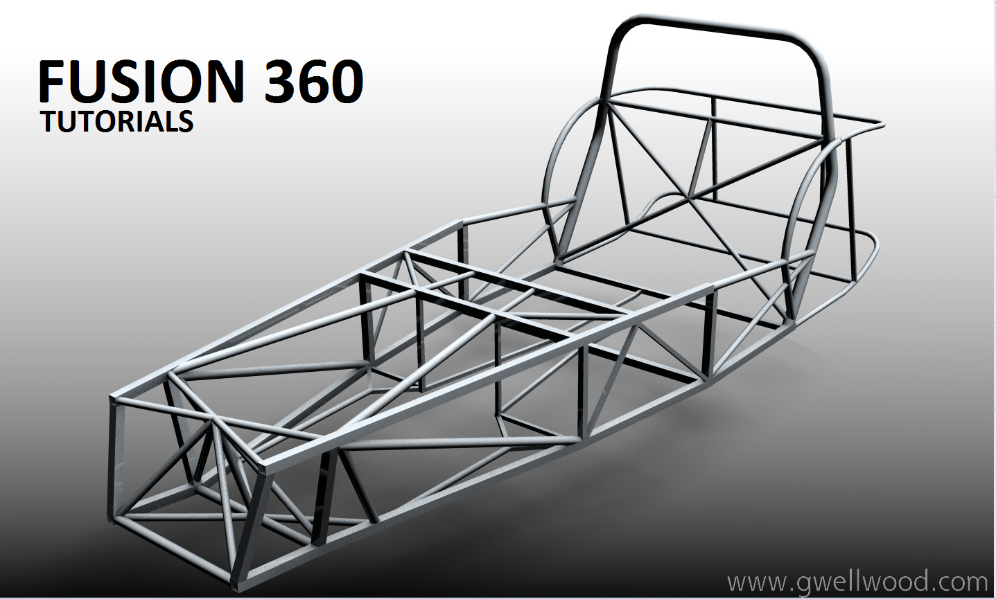
TUTORIALS
Adapted from Carnegie Mellon University Department of Engineering Pro/E Tutorials
For Your Reference: How To 3D Print
Extrusions, Sketching, & Cuts
Holes, Rounds & Chamfers
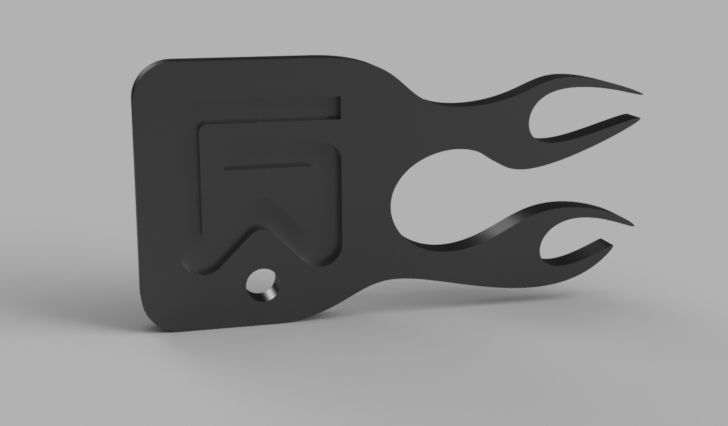
GET CREATIVE! PROJECT: KEYFOB
Shells, Ribs & Work Planes
Feature Modification & Manipulation
Revolves, Patterns & Copies
Sweeps
Lofts
DIMENSIONING
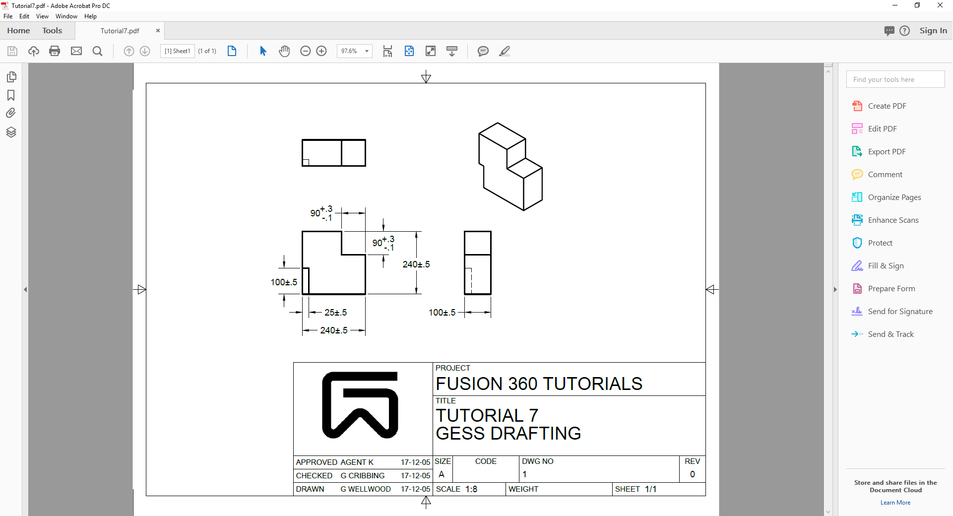
All Manufacturing and Fabrication industries depend on Drafting. Without Drafting, nothing can be manufactured.
The “drawings” that companies use to “Work” from are called “Working Drawings.” A Working Drawing must have enough information that someone could build the object as specified.
A Working Drawing must include:
-
- All the necessary views to explain the shape
- All the dimensions and specifications needed to build the object to size, using the proper materials
ASK YOURSELF – “Can this object be built without further instructions?”
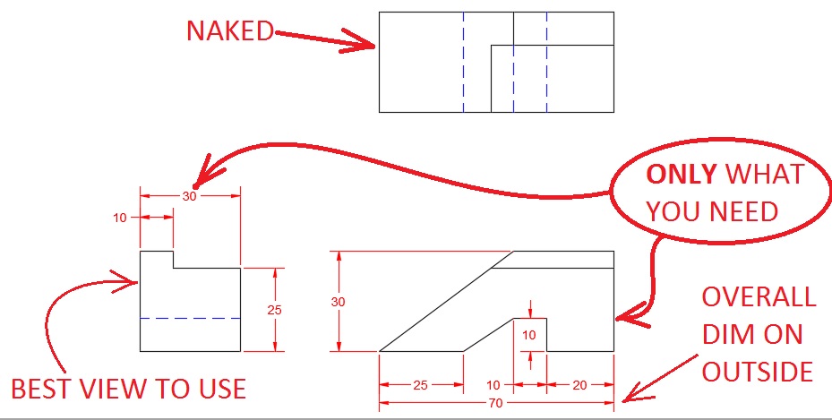
We need to talk DIMENSIONS
-
- One view is dimensioned AS MUCH AS YOU CAN
- On one view has WHATEVER ELSE YOU NEED
- THE LAST VIEW IS NAKED
ONLY show the dimensions you NEED to show to BUILD the object – NOTHING MORE.
DO NOT DIMENSION EVERY SINGLE LINE THAT EXISTS! – Be lazy! Only the work you HAVE to.
NO REDUNDANT DIMENSIONS (never dimension the same thing twice!).
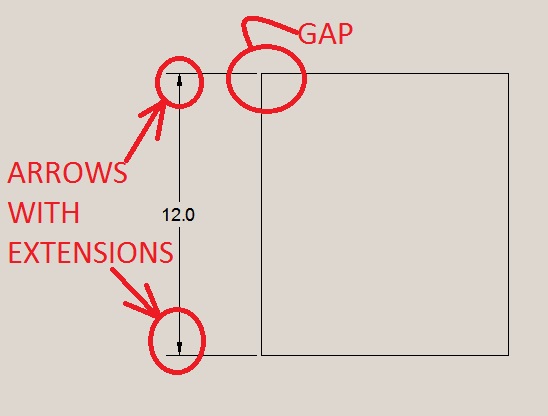
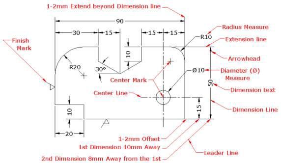
Dimension lines have ARROWS pointing to EXTENSION LINES.
Extension Lines DO NOT touch the object.
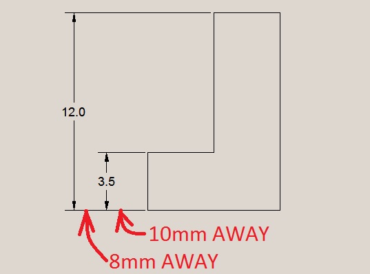
Dimension lines start 10mm from the object and then 8mm apart from each other
Overall dimensions are OUTSIDE smaller dimensions and SHALL NOT CROSS
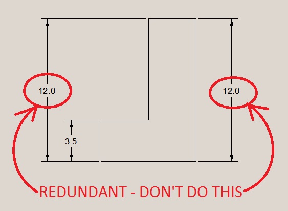
Do not duplicate dimensions
Do not duplicate dimensions
Do not duplicate dimensions
Do not duplicate dimensions
Dimension on the CLEAREST VIEW, usually:
-
- First: on the front view
- Secondly: on the top view (though in this example, the end view is more clear)
- Lastly: only if needed, on the side view
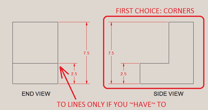
Dimensions go BETWEEN THE VIEWS
Dimensioning to CORNERS is better than LINES
DO NOT Dimension to hidden lines
(if you dimension to hidden lines, I’m going to punch you in the hidden line)
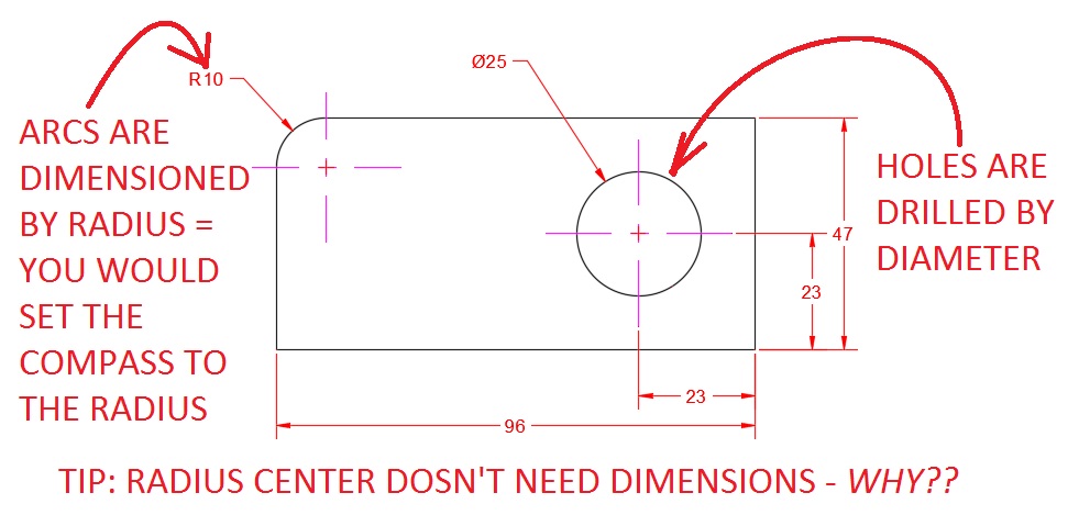
ARCS are dimensioned by RADIUS (you use a compass to draw them)
HOLES are dimensioned by DIAMETER (you use a drill to cut them)
YOU MUST DIMENSION HOLE CENTERS!!! (Where is the hole located??)
All-in-one Example
ENGINEERING DRAWINGS (“Working Drawings”)
Tutorial 8 DO NOT CONTINUE WITHOUT BEING CHECKED!
Problem 8 – Create Engineering Drawings for Problem 1
BONUS (especially if you WANT to be an Engineer):
Problem 8b – Create Engineering Drawings for Tutorial 4
-
-
-
- Dimension the location of the hole?
- Dimension the size of the hole?
- Dimension the center of the Radius?
- Dimension the size of the radius?
- Dimension the radius on the edges?
- Dimension the overall height?
- Dimension the overall width?
- Go back and read the rules of dimensioning
-
-
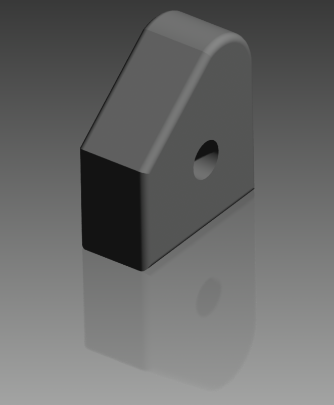
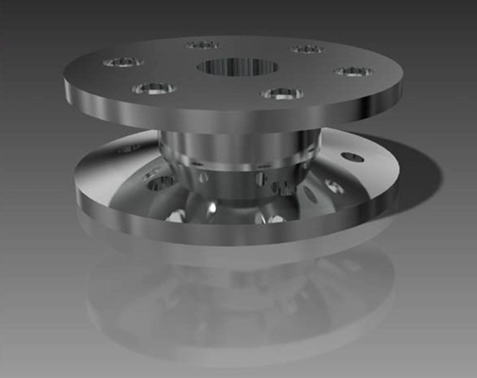
Problem 8c – Create Engineering Drawings for Tutorial 5
-
-
-
- Dimension the shape of the revolve?
- Dimension the sizes of the holes?
- Dimension the distance of holes from center?
- “Leader” to say “C-BORE” and counterbore size?
- Go back and read the rules of dimensioning
-
-
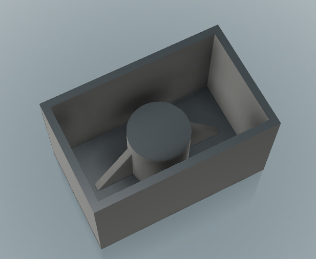
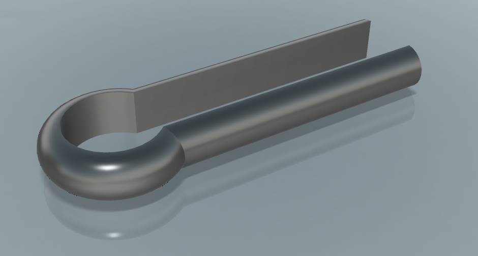
Problem 8d – Create Engineering Drawings for Tutorial 6A (Hair pin)
-
-
-
- Dimension the path?
- Dimension the profile?
- Convince me that you’ve learned this
-
-
SHOW your instructor the Problems on screen (I want to KNOW that you got this), then send the PDFs to the handin folder.
DO NOT CONTINUE WITHOUT BEING CHECKED!
Assembly Modeling
Sheet Metal Design
If you are not here by October 1st/March 1st, you’re going to run out of time
GET CREATIVE!
FUSION 3-PART CHALLENGE!
The parts shall count THREE, no more, no less. THREE shall be the number thou shalt count, and the number of the counting shall be THREE. Four shalt thou not count, neither count thou two, excepting that thou then proceedeth to THREE. Five is right out.
This Project must be completed THIS TERM;
Don’t waste your time
Don’t waste OTHER PEOPLE’S time;
THEY NEED TO COMPLETE THEIR PROJECT TOO
CLICK HERE TO PRINT MARKS SHEET
For Your Reference: How To 3D Print
>>> NO WEAPONS <<<
No derivatives of weapons, no miniaturized weapons, no functional or non-functional weapons, no insinuated weapons, no historical weapons, no futuristic weapons, no theoretical weapons, no philosophical weapons, no cleverly disguised weapons, no weapon components that could later be assembled into weapons, anything that looks anything like anything that could have anything to do with any kind of weapon is forbidden. Get over it.
THE PROJECT MUST BE 4 THINGS:
-
- Be a GADGET, TOOL, or CONTAINER
- (check out the MARKS SHEET – the HOOP you must jump)
- A: Each shape has extra techniques, TWO parts move as a SIMPLE MACHINE, and, when 3D Printed and assembled, does not come apart.
- B: Each shape as extra techniques, TWO parts move, when 3D Printed and assembled does not come apart
- C+: Each shape has extra technique, something moves, when 3D Printed and assembled does not come apart
- C: Basic geomteric shapes, something moves, when 3D Printed and assembled does not come apart
- !!MOVING PARTS MUST HAVE ABOUT 1.5mm CLEARANCE!!
- (check out the MARKS SHEET – the HOOP you must jump)
- Be ASSEMBLED from ONLY THREE DISTINCT PRINTABLE ASSEMBLEABLE parts
- A Single Part can have more than one technique applied
- “Single Part” example: A bicycle wheel (though it is made of many pieces, it is considered ONE part):
- Rim (revolve)
- Hub (revolve, hole, pattern)
- Spokes (sweep, thread, solid)
- Tire (revolve, solid, pattern)
- Valve stem (revolve, thread)
- You have permission to use “real” screws, springs, metal pins, and the like, as fasteners if need be
- Something MUST MOVE yet remain ATTACHED When 3D printed and assembled
- Use at least THREE DIFFERENT TECHNIQUES:
- Solid modeled parts
- Holes
- Shells
- Ribs
- Revolved parts
- Patterns
- Lofted parts
- Swept parts
- Sheet Metal
- Be a GADGET, TOOL, or CONTAINER
For Your Reference: How To 3D Print
HAND IN 5 THINGS:
-
- PRINTED 3D – Project (Click HOW TO 3D PRINT)
- PRINTED Engineering Drawings Booklet (PDF) (IE: Tutorial 8?)
- Page 1: TITLE PAGE with RENDERED VIEW (RENDERED!!!)
- Page 2: ASSEMBLY (no dimensions) (Use the “+” to add pages)
- Pages 3, 4, 5, etc…: PARTS – one page for EACH individual part (with dimensions)
- PRINT THE MARKS SHEET for marking
- BOOKLET (not project!) EXAMPLES:
- EXPLODED ANIMATION (IE: Tutorial 9?)
- EXPORT All *.avi files
- DIGITAL – ALL Project Files
- EXPORT All *.f3d *.jpg *.doc & etc. files
- CREATE A FOLDER labelled lastname_projectname, and COPY ALL your files into it.
- example: wellwood_sheet-metal-brake
- DRAG AND DROP the folder to “i:\1. Handin\!Wellwood”
- PRINTED MARK SHEET (below)
- PRINT for marking
- YOU mark yourself FIRST
- Click for Mark Sheet
(above) GO AND READ THAT AGAIN (above)
For Your Reference: How To 3D Print
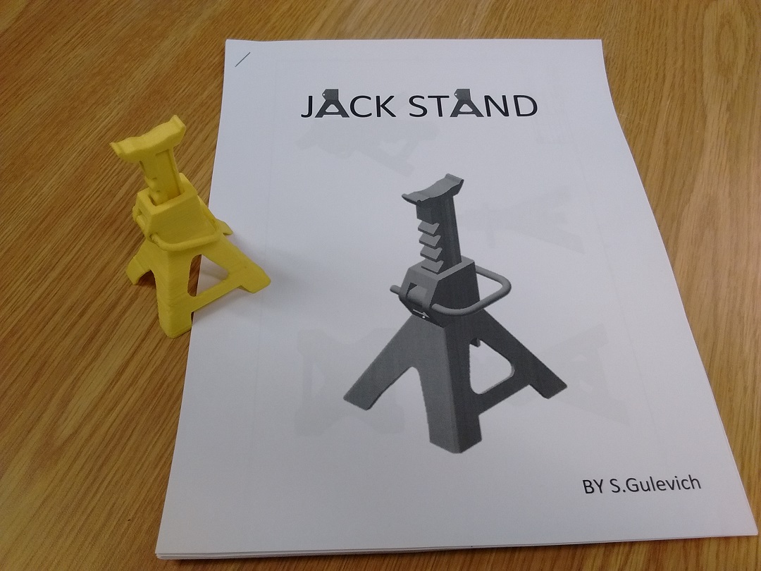
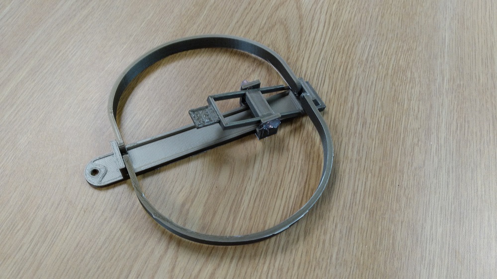
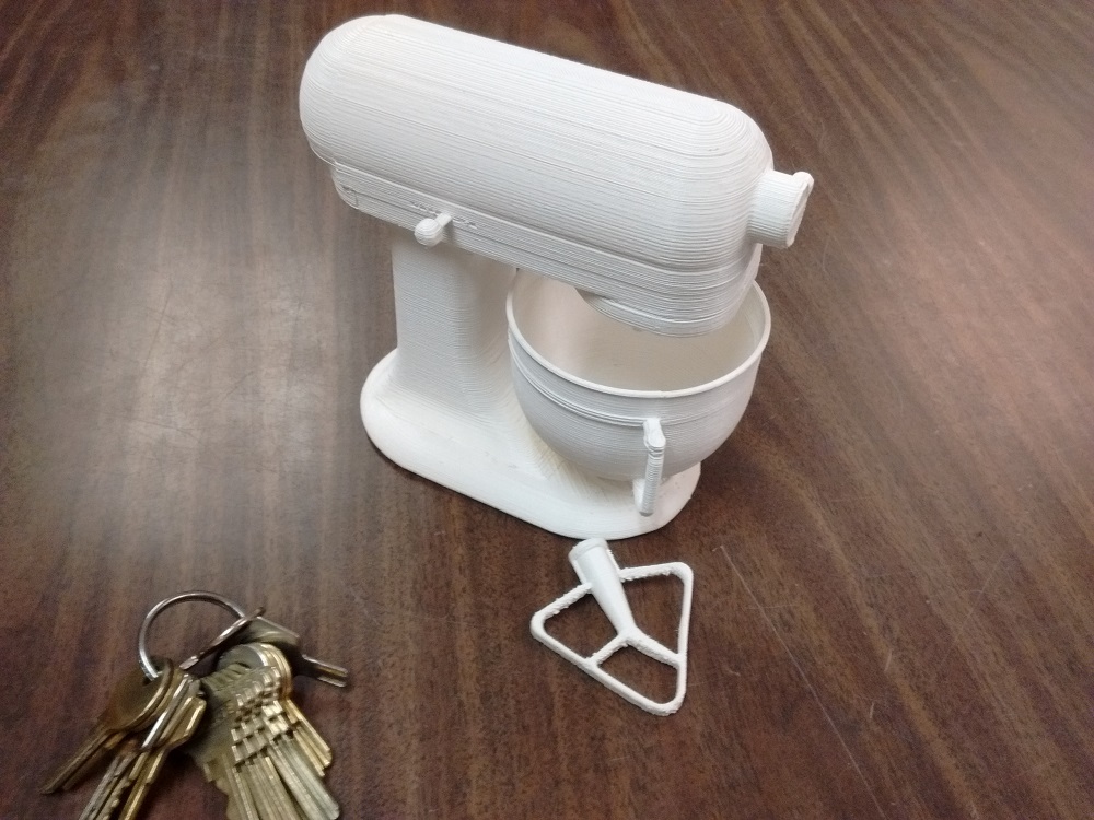
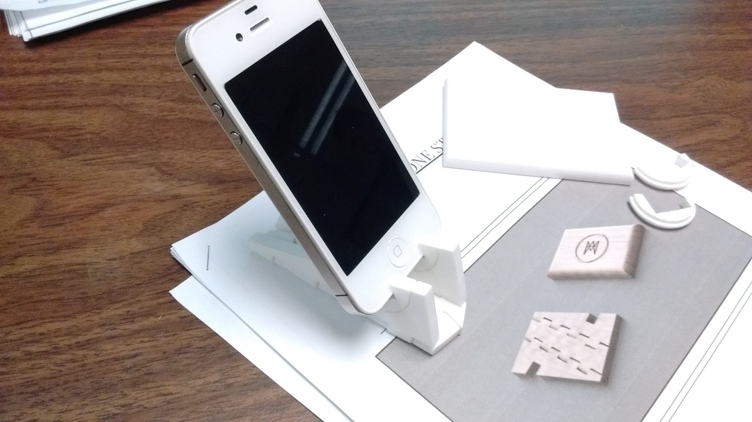
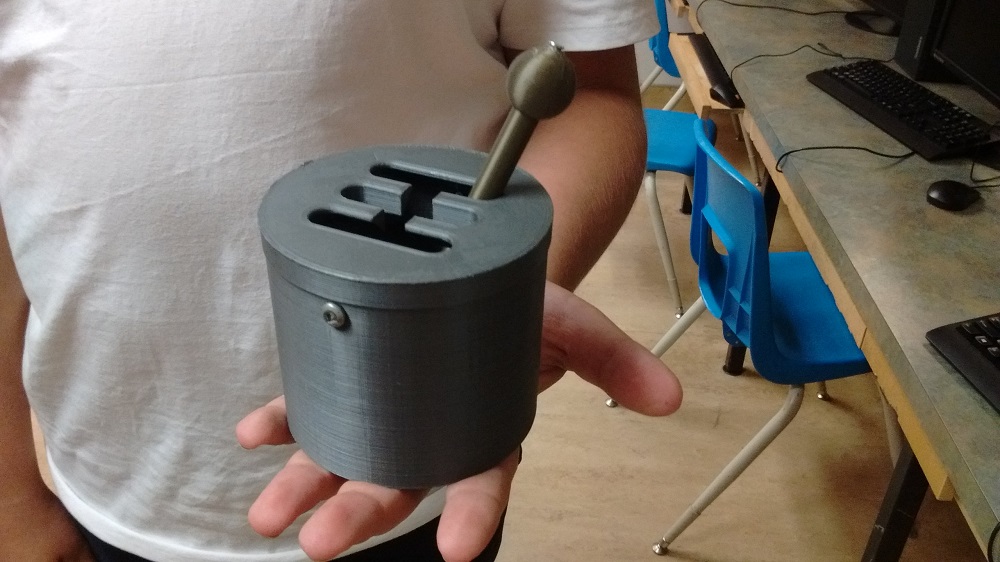
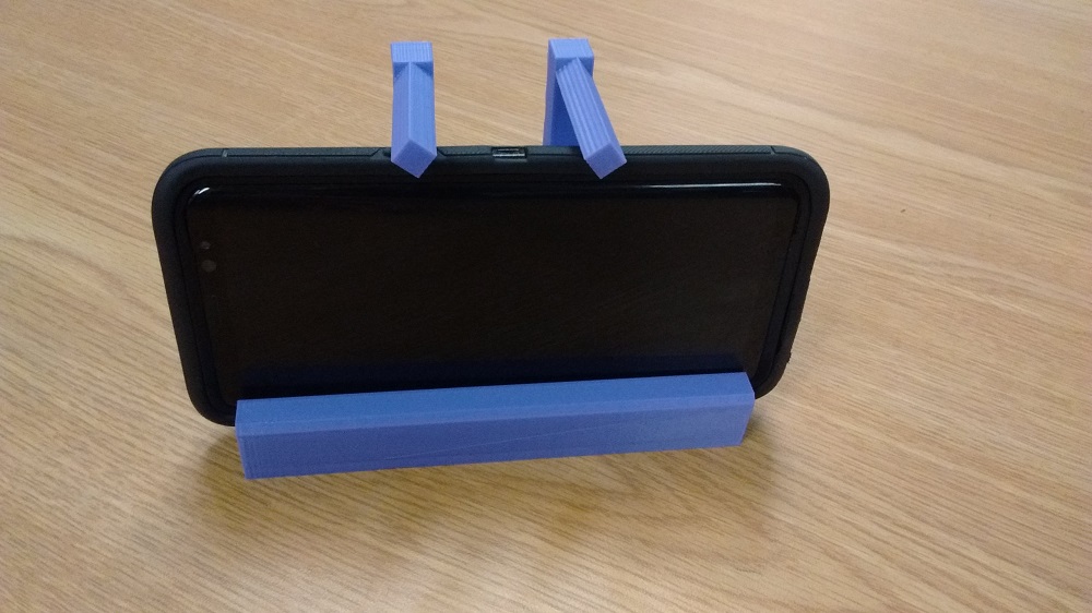
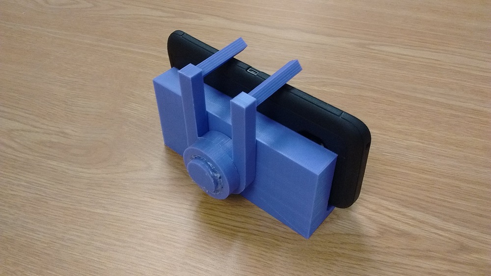
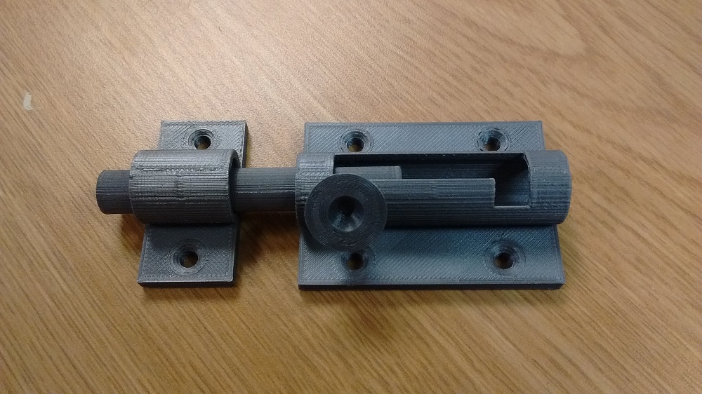
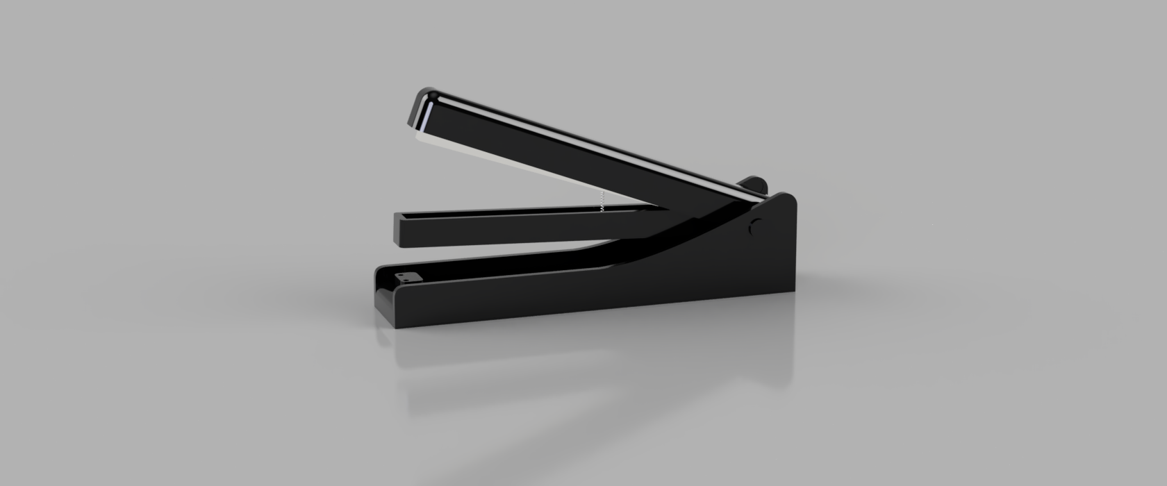
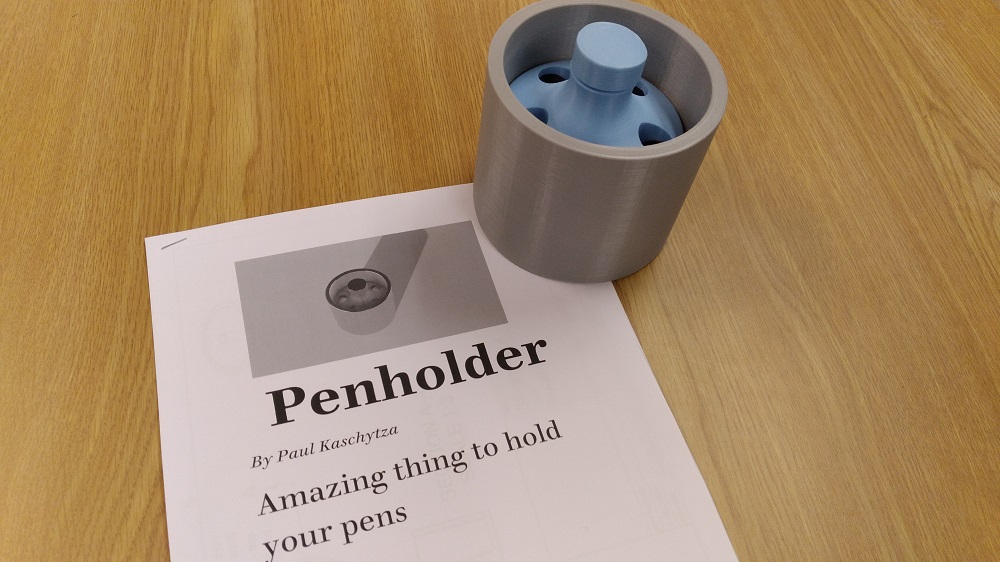
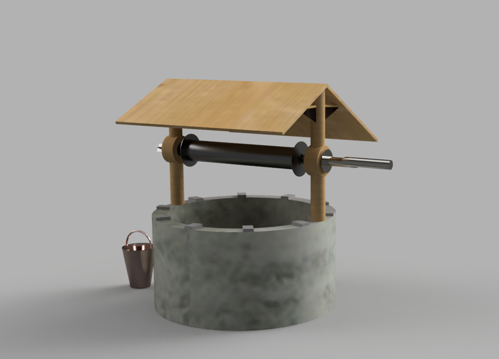
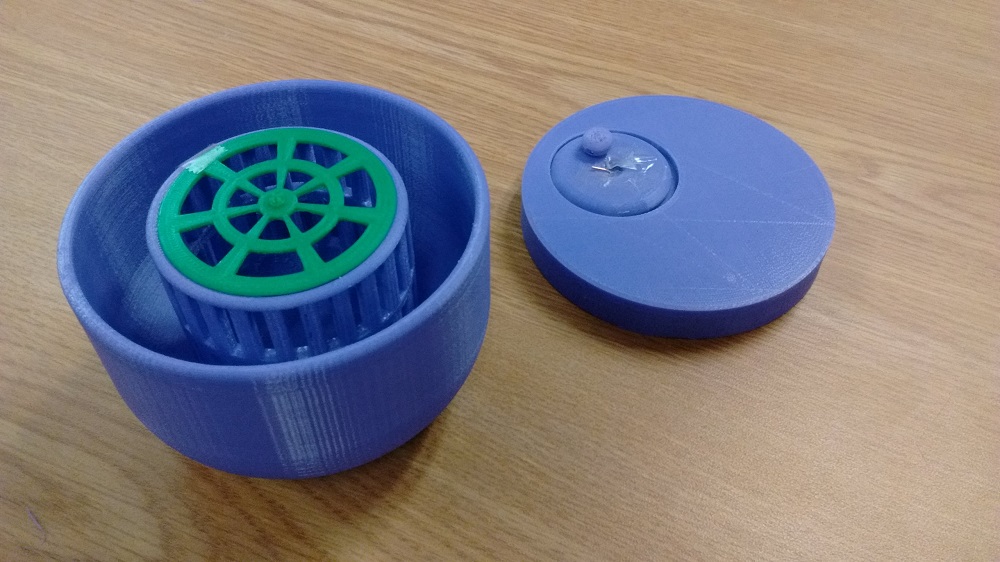
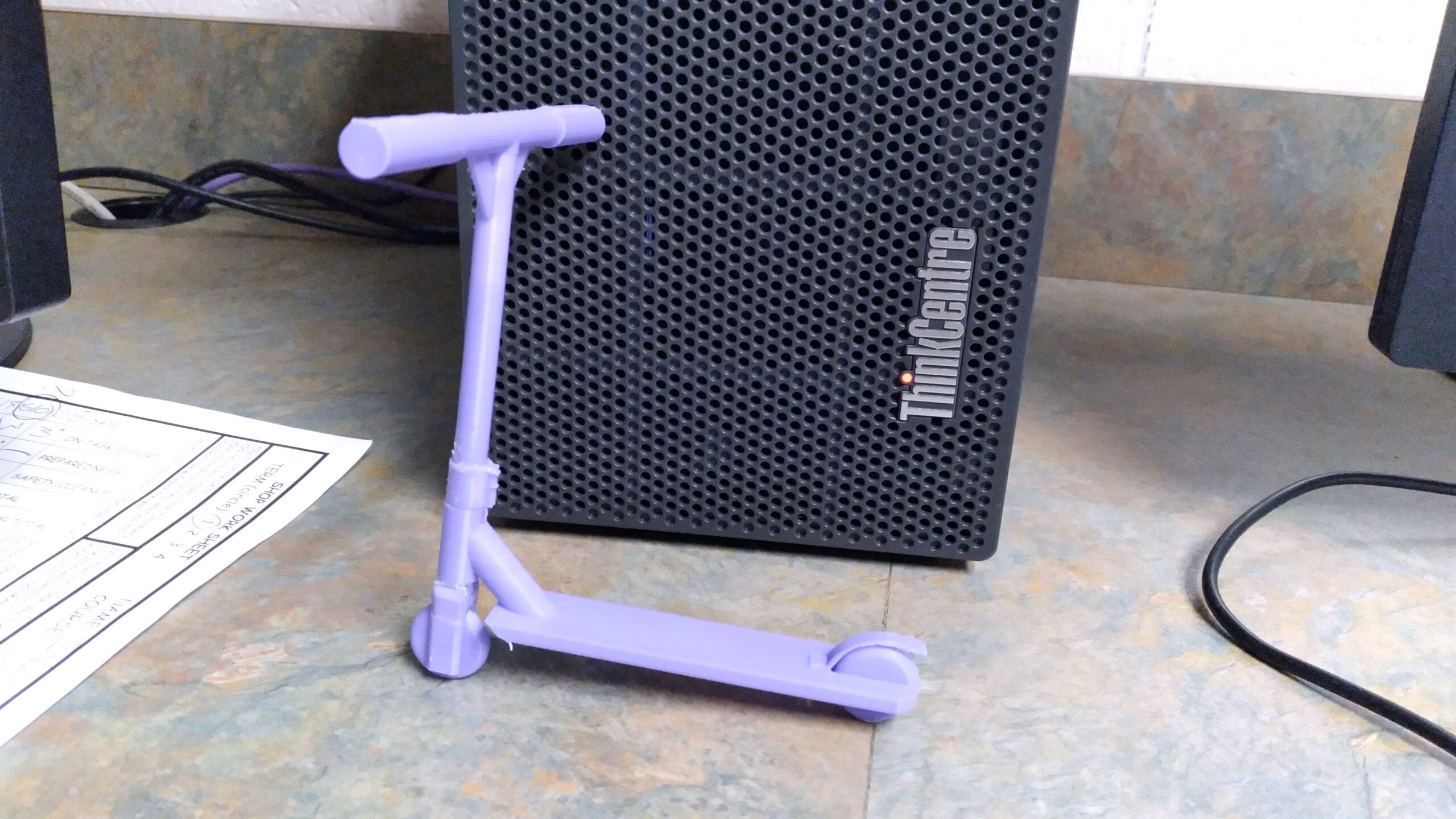
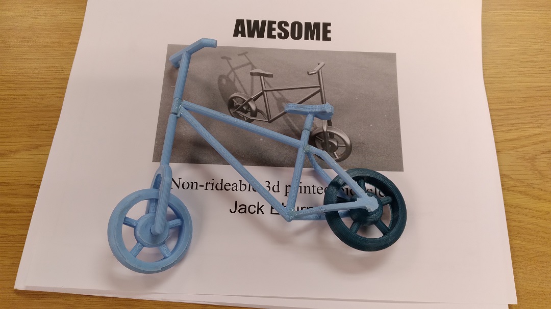
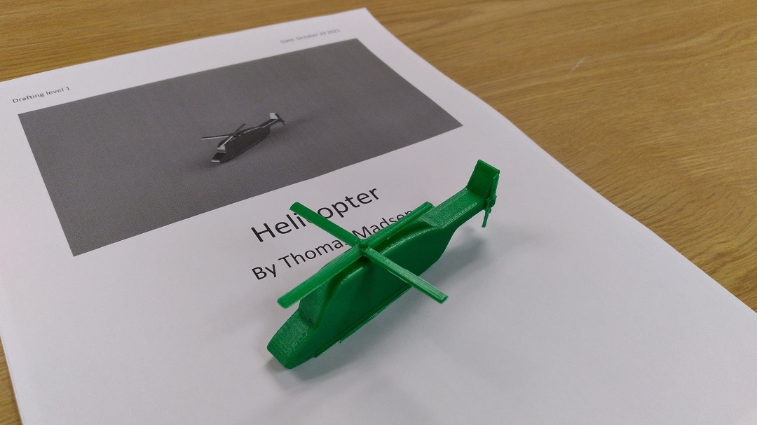
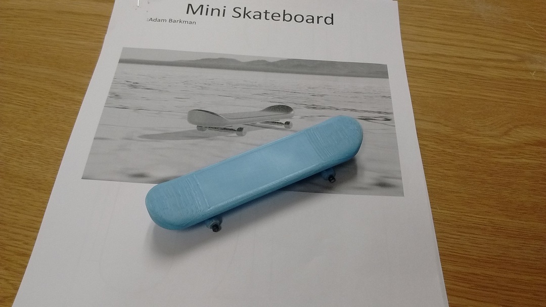
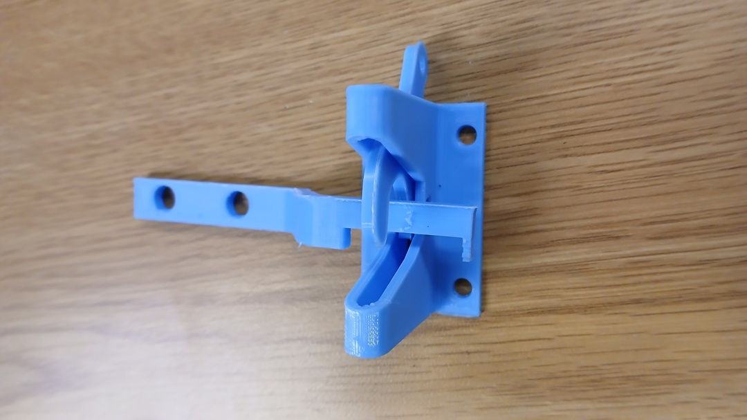
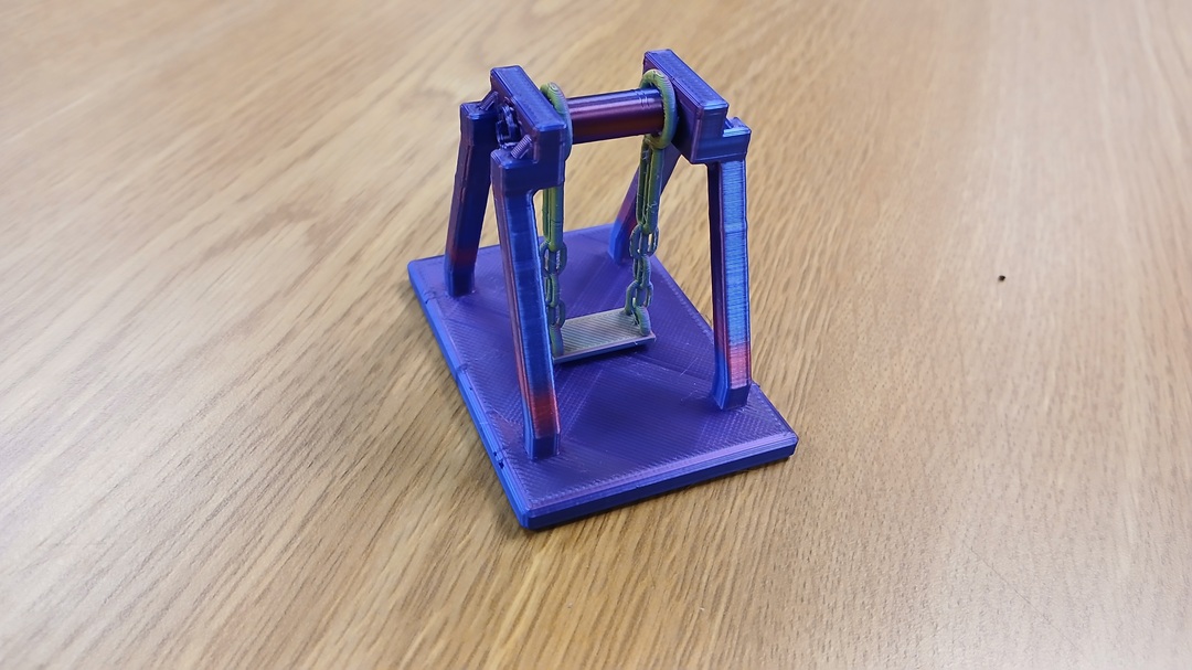
PAST EXAMPLES
 |
 |
 |
 |
 |
 |
 |
 |
 |
 |
 |
 |
 |
 |
 |
 |
 |
 |
 |
|
FINISHED?
Carry on into Architecture! That’s is a big unit too
Try to get ahead in case things slow you down!!