Tutorial 9: Assembly Modeling
Introduction
Fusion’s assembly module allows parts to be grouped into assemblies or sub-assemblies to model a complete part or mechanism. In this tutorial, you will learn how to create assemblies, apply constraints between parts, change view properties of parts, and create exploded views. These techniques will be applied to a pulley mechanism.
There are THREE sections to this TUTORIAL, you need to do all three (that’s where they are all here):
[1. ASSEMBLE ] [2. APPEARANCE ] [3. ANIMATION ]
Creating an Assembly
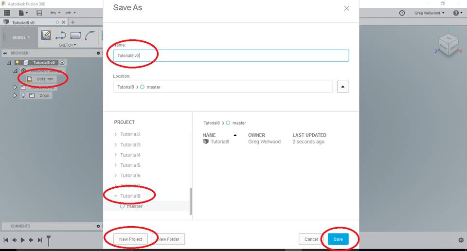
Start Fusion 360. Select the “Save” Icon, create a [NEW PROJECT] folder named “Tutorial9“, and from the BROWSER make sure it is [Units: mm].
YOU MUST KEEP YOUR FILES ORGANIZED! FOLDERS, NAMES, and LOCATIONS ARE IMPORTANT TO KEEPING YOUR FILES ORGANIZED!
For this tutorial, you will need to COPY parts you created in Problem 2 and Tutorial 5.
Right-click and Download the parts below:
You will need these parts later.
QUICK CLASSROOM DEMO:
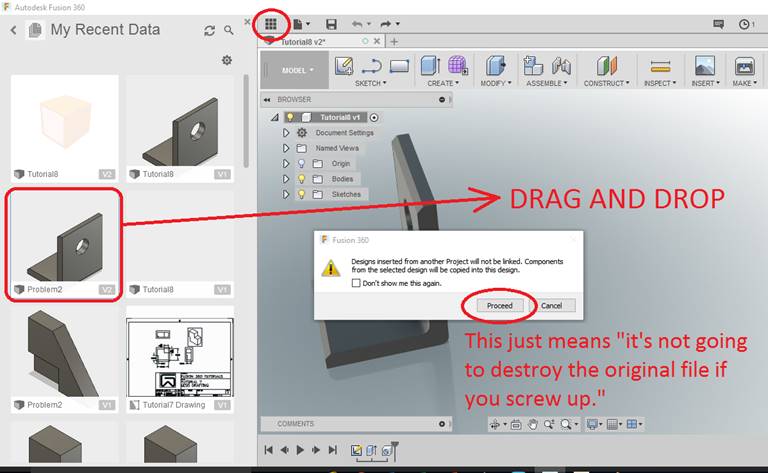
You will now begin to add parts. First, we need to place a Problem2 part. Click on the DATA PANEL (the stack of 9 squares at the top) to find your PROBLEM2, then Drag and Drop into Tutorial8. Fusion will warn you that it won’t mess with the original, just click Continue.
NOTE: If, when you insert the part, there is a CHAIN LINK beside the part name, that means that the inserted part is LINKED to the original file. This can be GOOD, or it can be BAD, depending on how much attention you pay to what you are doing.
If you alter the original file, your Assembly will UPDATE with the altered part. Sometimes this is good, sometimes it can be a problem.
Just click OK to drop it down anywhere.
GROUND TO PARENT (boo) vs. PIN (yay)
Your component probably came in automatically Grounded To Parent – this LOCKS it to the PROJECT, the PARENT in this case is the actual ASSEMBLY we are creating. If the ASSEMBLY moves, our grounded part will MOVE with it. A grounded object will have an ANCHOR icon in its icon in the browser.
A better option for us here is to PIN the object to the universe so it doesn’t move at all. Find your part in the BROWSER, right-click on it, and UN-click GROUND TO PARENT. and CLICK PIN. Our assembly needs to be PINNED to reality. So do some of my friends, truth be told. A pinned object will have a RED THUMBTACK in its icon in the browser.
USUALLY ONLY ONE COMPONENT IN THE ASSEMBLY NEEDS TO BE PINNED – PICK THE “BASE” OF WHATEVER IT IS YOU ARE BUILDING
YOU CAN GROUND TO PARENT OTHER PARTS IF ITS HELPFUL

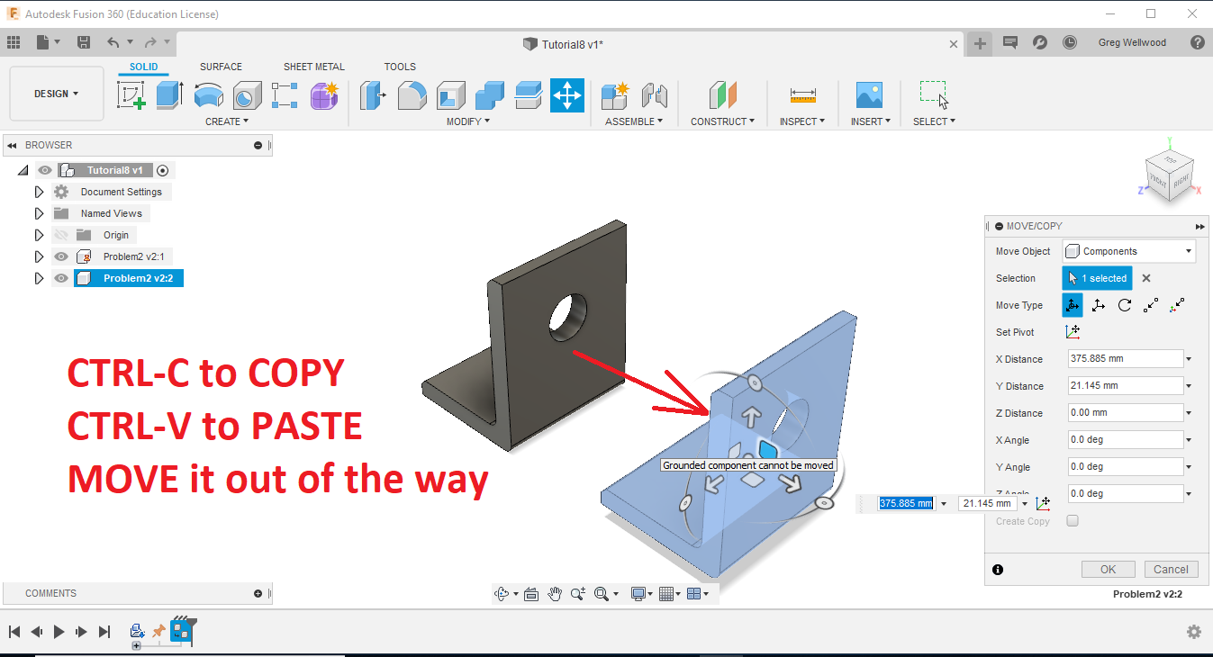
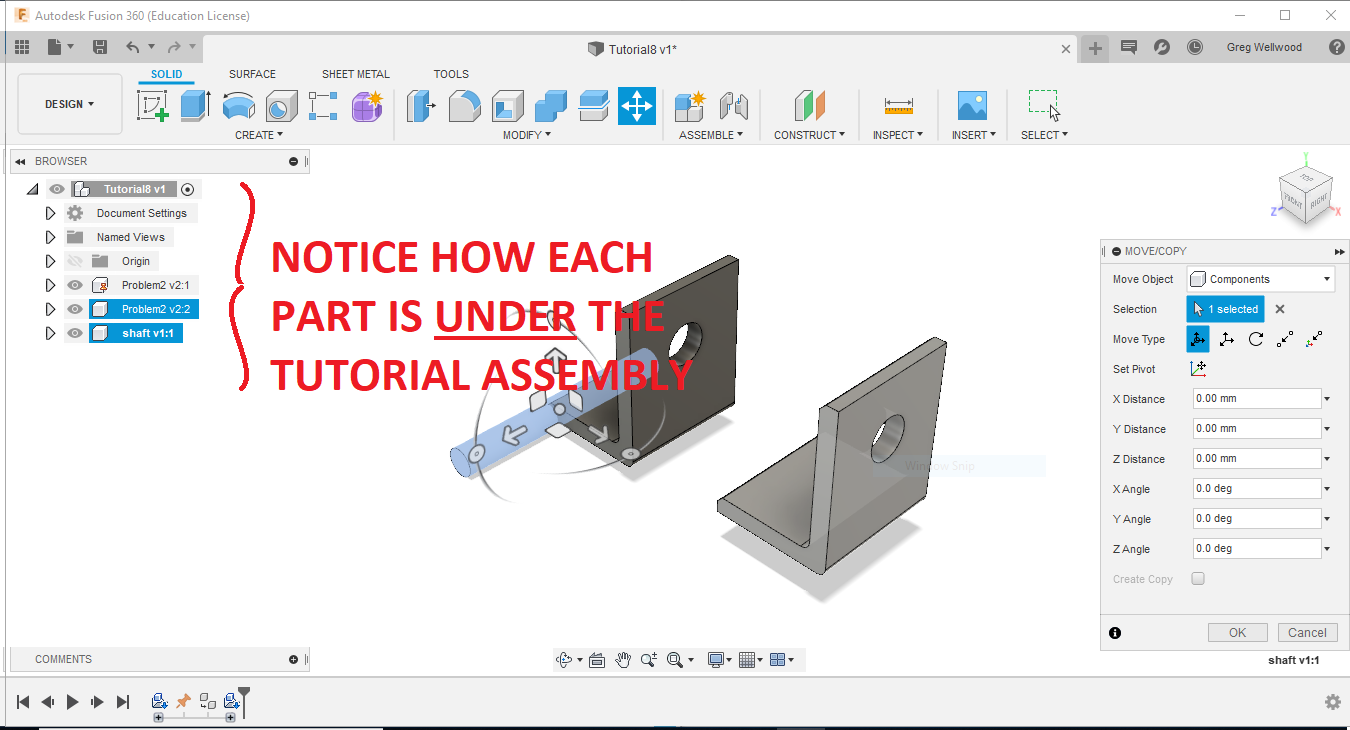
Click on the Problem2 part (I usually do so in the BROWSER so I don’t miss any part of it), type [CTRL-C] to COPY it, hit [ESC] to UNSELECT it, then type [CTRL-V] to paste it. Fusion will plunk that new object right on top of the existing one. You need to move it out of the way.
Click the Component AS PASTED and MOVE, dragging it out of the way (it doesn’t matter where at this point).
We now need to UPLOAD the two files you saved.
Don’t know what I’m talking about?
Delete your work, and start this Tutorial again.
But this time, actually READ the steps.
GETTING FILES INTO FUSION:
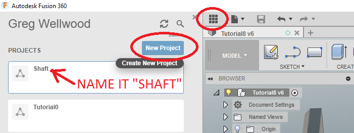
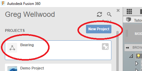
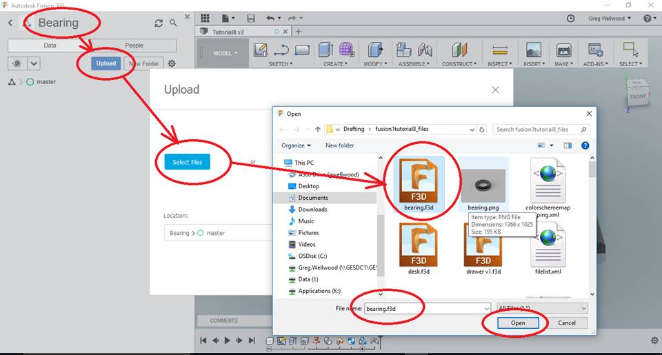
Open the DATA PANEL, and click NEW PROJECT, call it SHAFT. Double click that new (and empty) file, and click UPLOAD. Select the file you saved from your DOWNLOADS folder, and click OK.
Now DRAG and DROP the SHAFT into your workspace. Place it anywhere, don’t worry about where.
JOINTS
Let’s attach the SHAFT to the PINNED L-BRACKET.
From the ASSEMBLE section of the RIBBON MENU, select JOINT.
Click the OUTER EDGE of one of the ends of the SHAFT (not the cylinder, not the flat), then select the OUTER EDGE of the hole on the L-BRACKET.
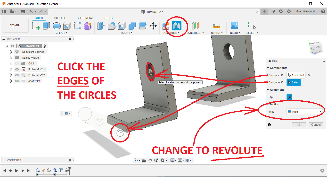
You should see the SHAFT move its way over to the HOLE, and then ROTATE by itself. If, instead, it does the HIPPY-SHAKE-SHAKE, you left it on RIGID – Edit the Feature, and change it to REVOLUTE.
If you set it to REVOLUTE , you should be able to click on the SHAFT, and rotate it. TRY IT!
NOTE: ALWAYS PICK THE OBJECT THAT WILL BE MOVED FIRST, THEN PICK WHERE IT IS MOVING TO.
Now, let’s JOINT the other L-BRACKET. Again, chose JOINT from the ASSEMBLE section of the RIBBON MENU, and Click the OUTER EDGE of the L-BRACKET HOLE, and then the EDGE of the SHAFT. Make it REVOLUTE, and you should see the L-BRACKET move into place, and then rotate around the shaft.
THAT LOOKS DRUNK, Mr. WELLWOOD! WHAT THE HECK!?
Don’t worry about it. That’s next.
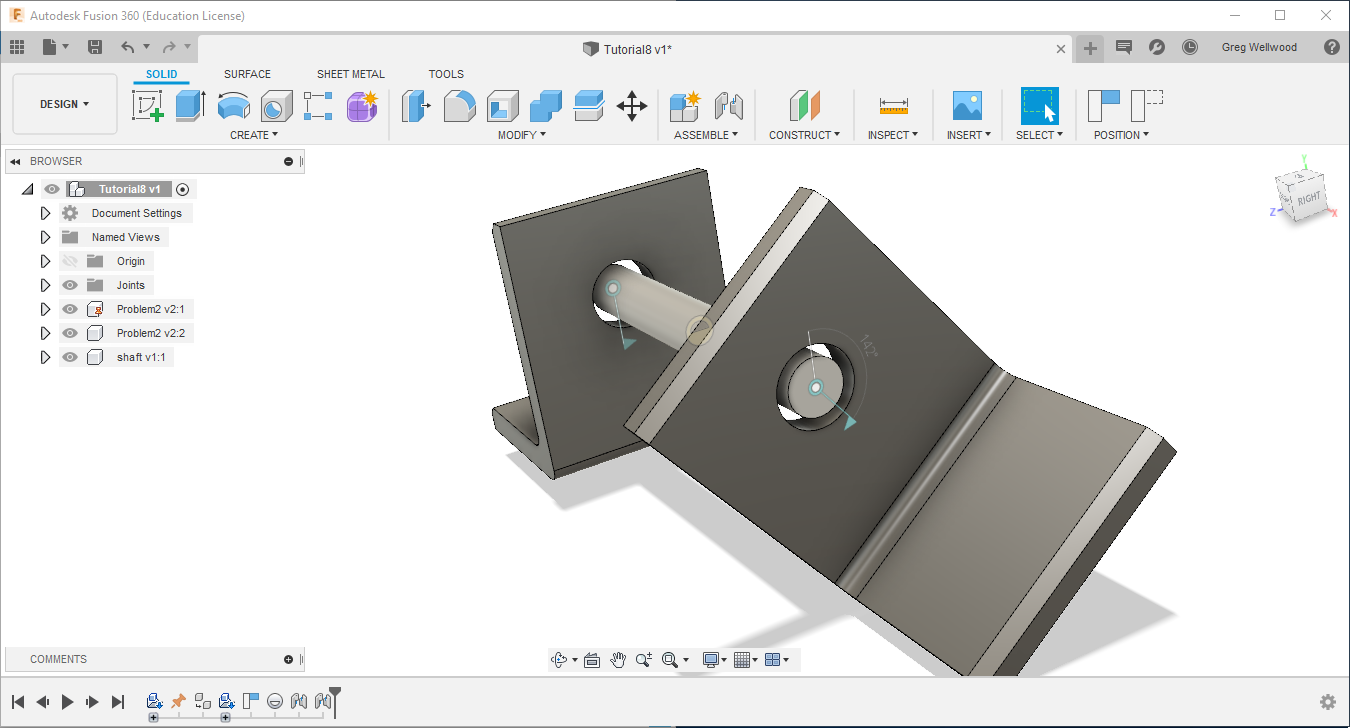
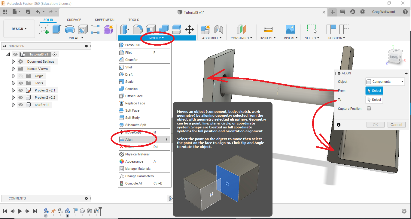
From the MODIFY section of the RIBBON MENU, select ALIGN, and select ONE side from EACH of the L-BRACKETS that you want lined up with each other.
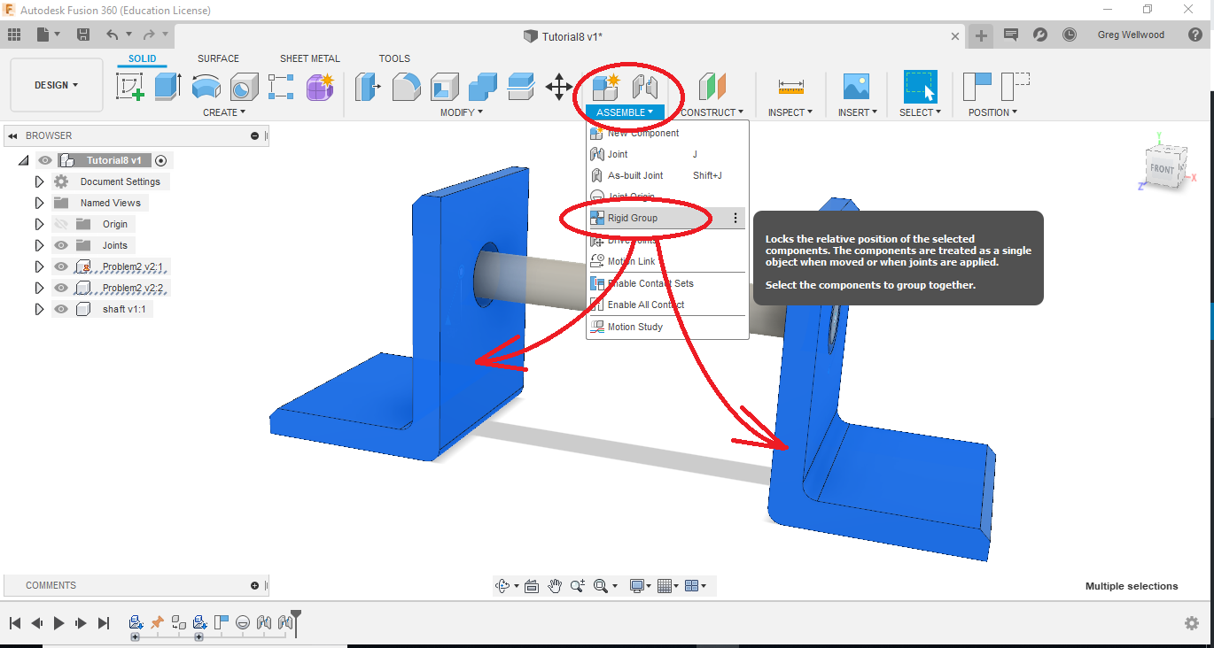
The L-BRACKET should swing into place and look perfect (YAY!). BUT, If you click and MOVE it, it will ROTATE AROUND THE SHAFT (BOO!). Before you move it, select BOTH L-BRACKETS, and from the ASSEMBLE section of the RIBBON MENU, select RIGID GROUP. They are now FIXED, and cannot be moved. MAKE SURE YOU CAN STILL ROTATE THE SHAFT.
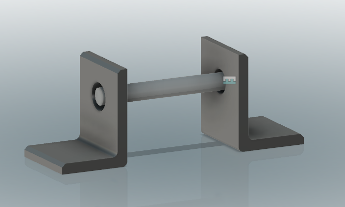
This should make everything hunky-dory. Except the shaft is levitating, which defies the laws of Physics. Let’s put a bearing in there next.
If you have not already done so, upload the Bearing file into your Fusion Cloud of goodness.
DRAG AND DROP the Bearing file onto your project.
Type J on your keyboard to select JOINT.
When you JOINT, pick first the part you want to MOVE. You will need to ROTATE your view slightly so you can actually grab the MIDDLE of the bearing.

Now pick the hole in the L-Bracket (you may need to rotate the view), then you should be able to have the bearing move into place.
NOTE: If you cannot actually grab the middle of the hole in the L bracket, try UN-EYEBALLING the shaft so Fusion can see inside.

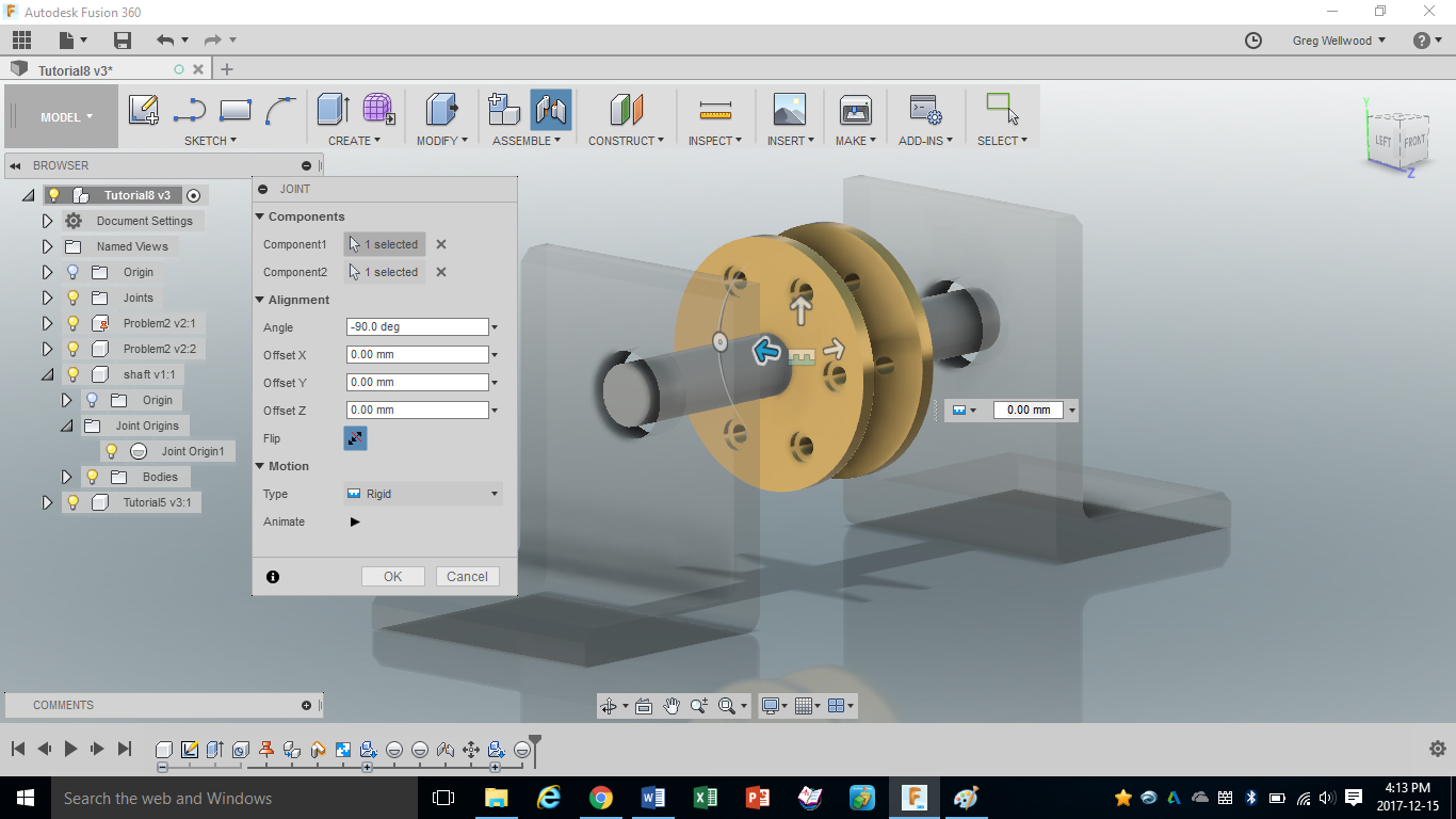
Now use JOINT in the RIBBON MENU to select and JOIN the middle of the PULLEY to the middle of the SHAFT. Make them RIGID.
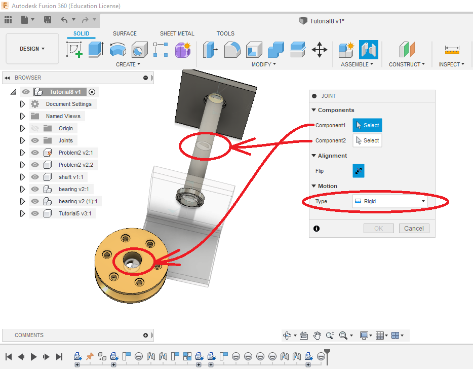
The PULLEY should move into place and do the HIPPY-SHAKE-SHAKE.
Click on the pulley and give it a spin. The shaft should rotate freely, the pulley should be fixed to the shaft, but not move anywhere off the shaft.
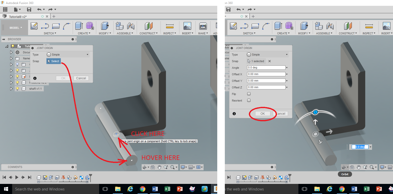
A NOTE ABOUT JOINT ORIGINS for “FUTURE YOU”
For the most part, Fusion is reasonably intuitive, and you can just click useful joinable pieces of your parts, and Fusion will “joint” them (like we did above). However, sometimes you need to provide a SPECIFIC PLACE where YOU want them to joint. In this case, you will need to create a JOINT ORIGIN.
Joint Origins provide a spot where parts can be JOINTED. This is super handy when assembling, especially when what you’re jointing isn’t, shall we say, “normal” or “expected.”
There is a significant caveat here (Caveat: Latin for “Beware”): You MUST either UN-LINK the component in the assembly (then activate), or add a Joint Origin IN THE PART FILE ITSELF, NOT THE ASSEMBLY.
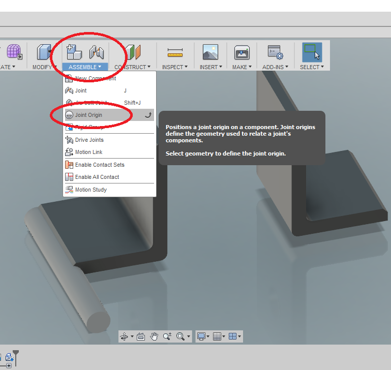
From the ASSEMBLE Tab on the Ribbon Menu, (of the un-linked or independent file) click JOINT ORIGIN, then play with it to put the Joint Origin where you want it.
If you did not BREAK THE CHAIN, you will need to UPDATE the Assembly (look for the caution triangle at the top of the screen)
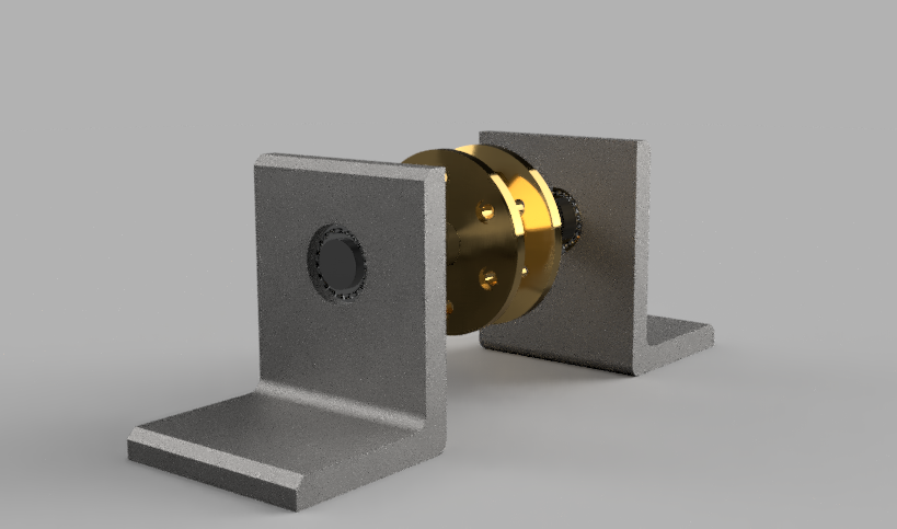
Playing with RENDER:
CHECKLIST:
Is the first L-Bracket GROUNDED?
Are all the parts JOINED?
Does the Pulley ROTATE?
YOU ARE NOT DONE YET!
SHOW YOUR INSTRUCTOR ON SCREEN!
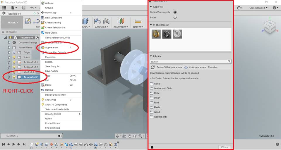
Modifying Appearances
You can only alter the appearance of parts that are NOT LINKED (Chain-link icon). You can either OPEN the actual part file and alter the appearance, OR you can BREAK the LINK (right click to do so).
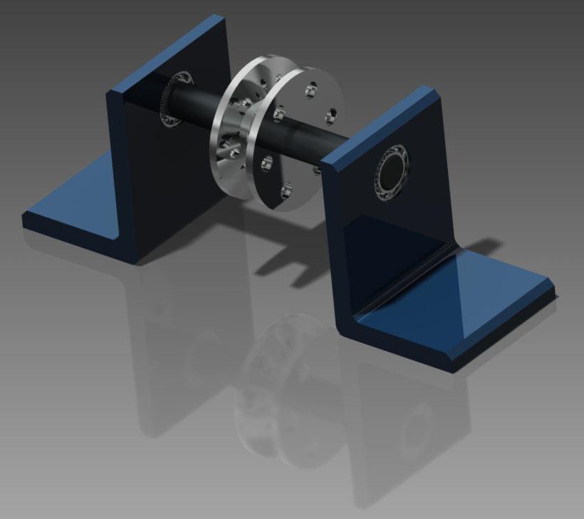
Right-Click on an UN-LINKED component of your assembly, and pick APPEARANCE (it looks like a colour wheel. You can also just type “A“). You can change component color, texture, and even transparency to whatever you desire. Experiment and make your assembly look awesome!
Exploded Views
In this section you will create an exploded view of the assembly.
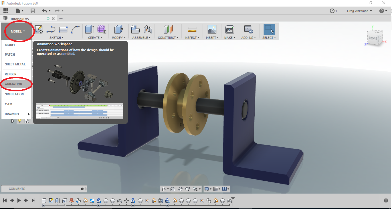
From the [DESIGN] Tab of the RIBBON MENU, select [ANIMATION].
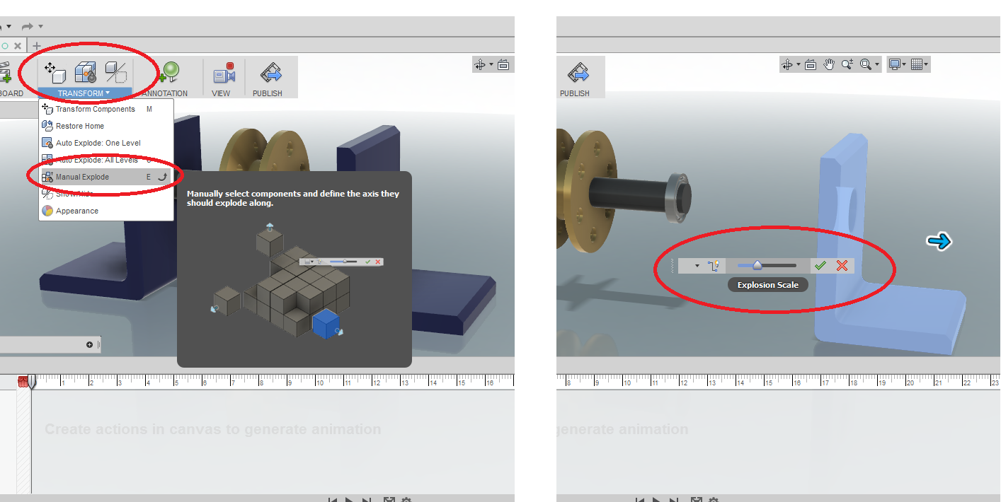
From the [TRANSFORM] tab of the Ribbon Menu, select [MANUAL EXPLODE], and select the RIGHT SIDE L-bracket. Controls should appear, allowing you to drag it off to the side. Repeat with all the other components, spacing them neatly, evenly, and logically (I’m looking at YOU, Sub Zero!). You could, in fact, try out some of the other commands in there. Let me know what works best for you!
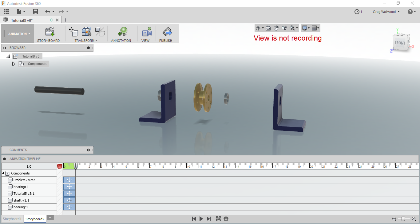
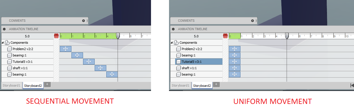
Press PLAY and see if you like the Exploded Animation. Make adjustments to the location of any components if needed. Then click PUBLISH to save the animated video to your computer.
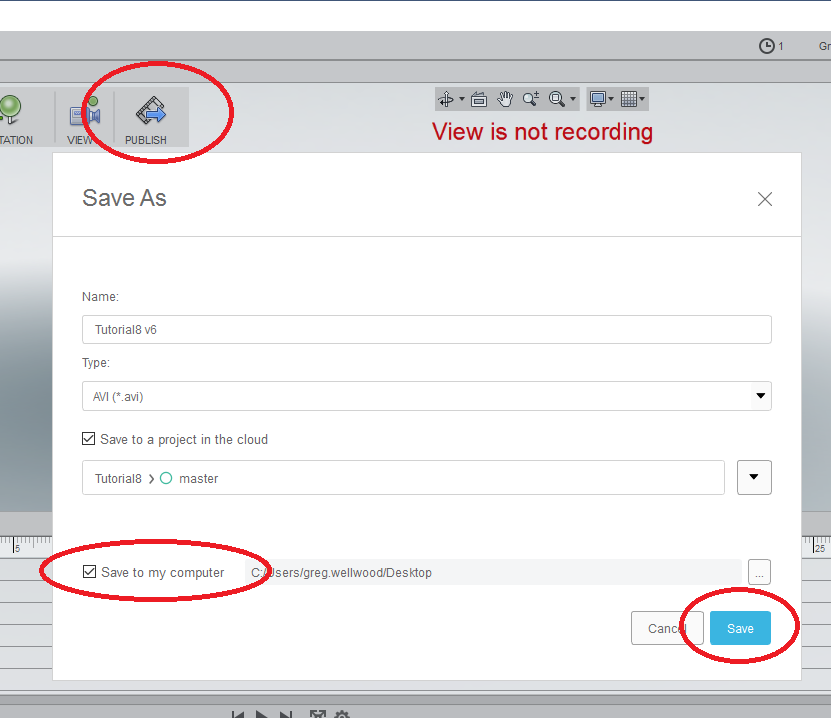
SHOW your Instructor the AWESOME video you made on screen. PUBLISH the video to the HANDIN FOLDER. UPLOAD it to your YouTube account, and make MOOLAH!
Now complete Problem 9