Tutorial 6: Sweeps
Introduction
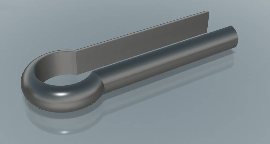
Sweeping and lofting are useful techniques for designing parts which may be difficult to model with extrusions or revolves. Unlike those other modeling techniques, sweeps and lofts allow for parts with varying cross-sections and parts that twist or bend. In this section, you will create a constant cross-section U-shaped part using a sweep.
Think of a SWEEP as an EXTRUDE that FOLLOWS A PATH.
Creating a Swept Part
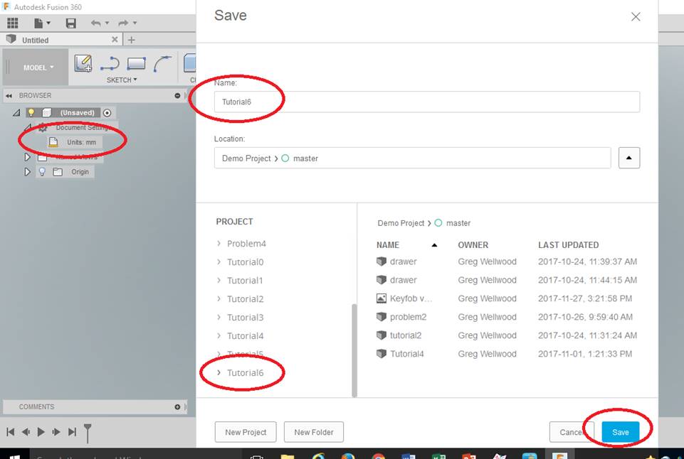
Start Fusion 360. Select the “Save” Icon, create a [NEW PROJECT] folder named “Tutorial6“, and from the BROWSER make sure it is [Units: mm].
YOU MUST KEEP YOUR FILES ORGANIZED! FOLDERS, NAMES, and LOCATIONS ARE IMPORTANT TO KEEPING YOUR FILES ORGANIZED!
In order to create a SWEEP, Fusion first needs to know a PROFILE, and a PATH for the profile to follow.
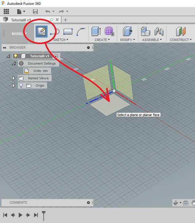
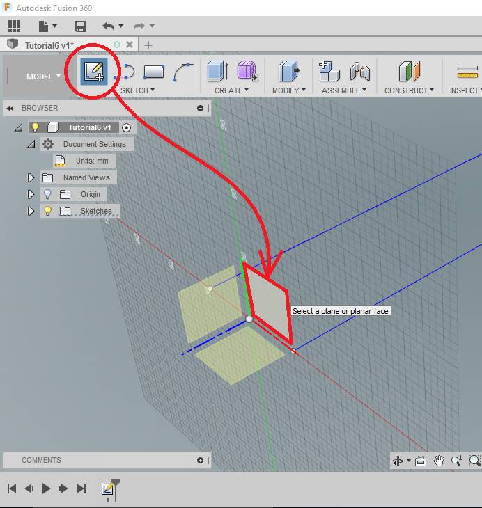
Start by selecting CREATE SKETCH from the Sketch Tab of the Ribbon Menu, and select the Horizontal Sketch Plane
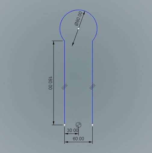
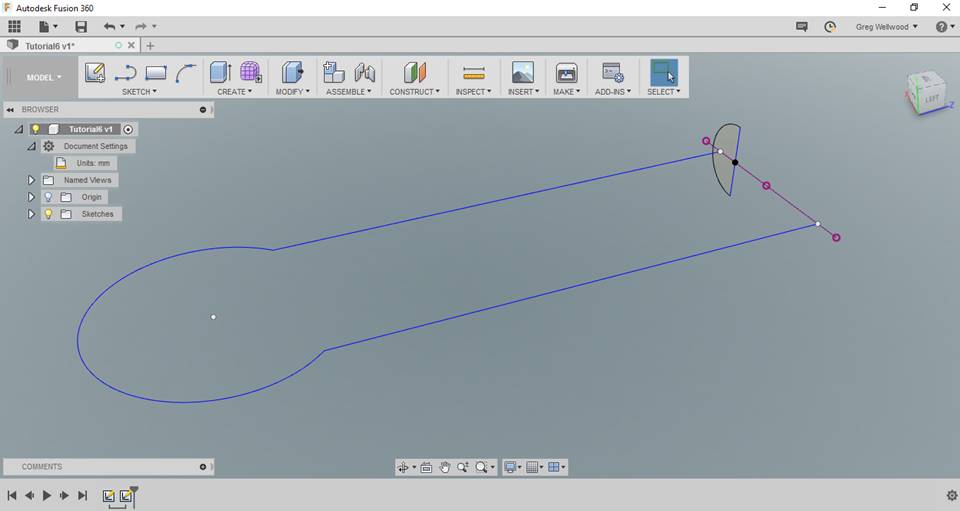
Draw the image as shown below as a PATH, then click [FINISH SKETCH]. You need the legs to START and END on the Horizontal line (a work plane we will need later). Kind of looks like a cotter pin.
Next select Create Sketch from the Sketch Tab of the Ribbon Menu, and select the vertical sketch plane where the legs started and ended.
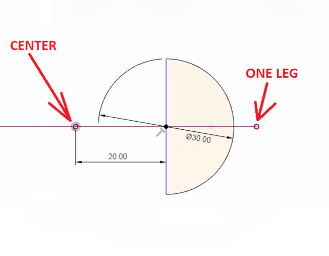
Sketch a PROFILE that looks like this, and click [FINISH SKETCH]. The Profile doesn’t actually have to touch the path for this to work. Looks like a semi-circle.
You should now see a PROFILE and a PATH on the screen.
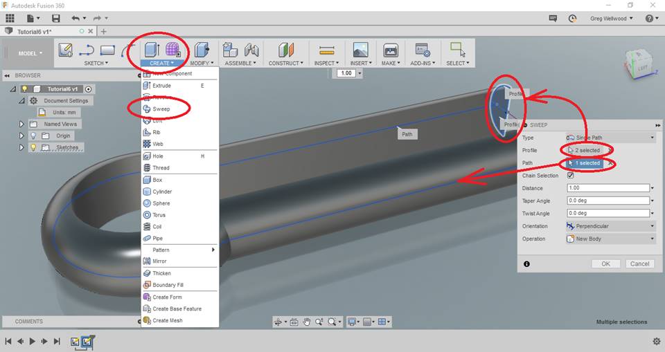
Select SWEEP from the CREATE Tab of the Ribbon Menu. For the Profile, click the semi-circle sketch you made (I had to click both halves on mine), and for the Path, click the Cotter-Pin shaped sketch you drew. Fusion should work its magic.
Make sure you save your work!
WANT IT MARKED?
Use the SNIPPING TOOL to do a WINDOW screen capture, and save the files into the HANDIN FOLDER with YOUR NAME and TUTORIAL/PROBLEM NAME (ie: wellwood-tutorial-6.png)
Now complete Problem 6.