Tutorial 3: Shells, Ribs, and Work Planes
Introduction
Work Planes are used as sketching surfaces and references for creating and construction features. In this section, you will learn to use Work Planes to create a rib. You will learn how to create several basic features.
Creating Base Shape
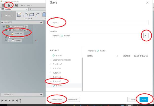
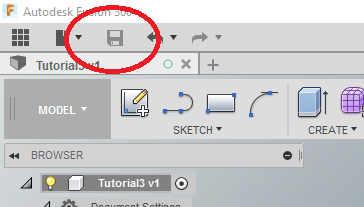
Start Fusion 360. Select the “Save” Icon, create a [NEW PROJECT] folder named “Tutorial3“, and from the BROWSER make sure it is [Units: mm].
YOU MUST KEEP YOUR FILES ORGANIZED! FOLDERS, NAMES, and LOCATIONS ARE IMPORTANT TO KEEPING YOUR FILES ORGANIZED!
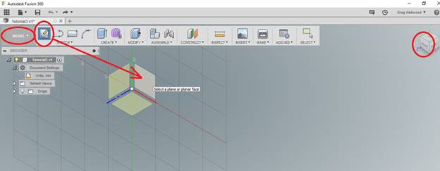
From [DESIGN] tab (used to be called “model” below) on the Ribbon Menu, click [Sketch], pick the FRONT (x,y) plane and enter SKETCH
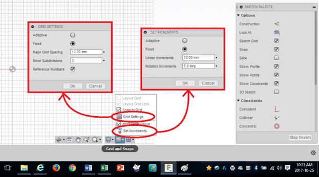
From [GRID and SNAPS] at the bottom of your screen, click [GRID SETTINGS], and Major Grid Spacing to 10mm with Minor Subdivisions to 3. Change [SET INCREMENTS] to 10mm. If the grid lines are not visible, make sure they are checked.
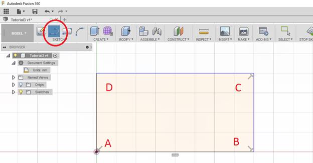
Type L on your keyboard to begin a LINE. Rough sketch a rectangle as shown below, click points A, B, C, D, and return to A – Don’t even count squares, just plunk down a rectangle.
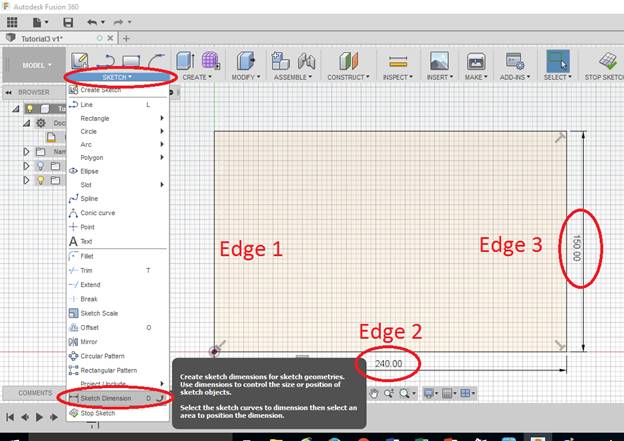
Type D to DIMENSION your sketch. One way to dimension an edge is to click both Edge 1 and Edge 3 to dimension the 240mm length of Edge 2. The other way is just click the line you want to dimension: click only Edge 3 and drag the dimension off to the side. A confirmation dialogue box will pop up each time – you can change the dimension if you have to, and your drawing will automatically adjust. Make Edge 3 150mm.
Click the [FINISH SKETCH] from the Ribbon Menu to exit the Sketch.
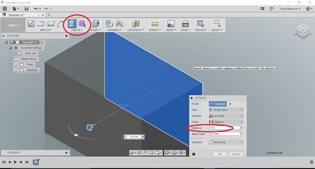
Type E to automatically enter [Extrude] from [CREATE] on the Ribbon Menu, and extrude to a depth of 150
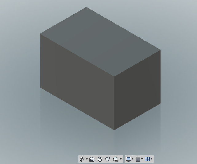
You should now see this:
Creating a Shell
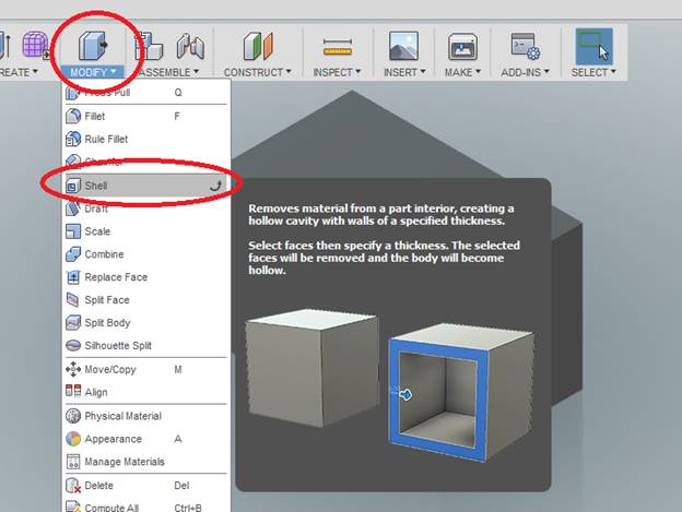
Select Shell from [Modify] on the [DESIGN] ribbon menu (hovering over a button often shows what the button does)
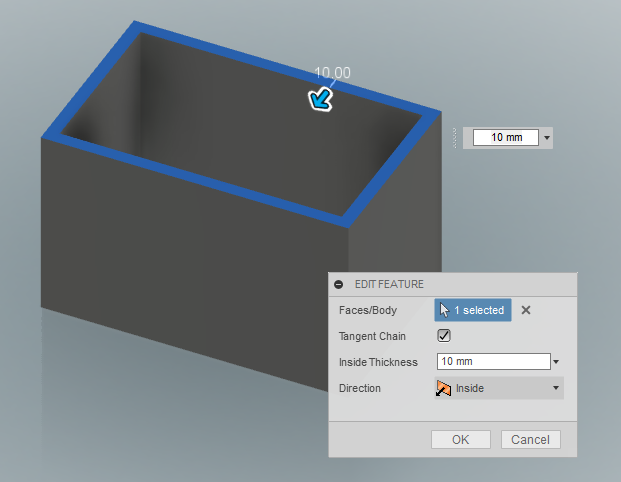
Click the Top of the box to begin the Shell. Input 10 for the Shell Thickness. It will Shell open to the side you click (interestingly, if you hold [Shift] down and select another side, it will Shell through both sides).
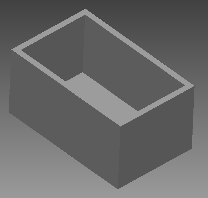
Click [OK]. You should see the shelled part shown below:
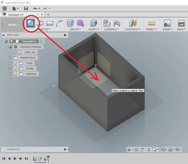
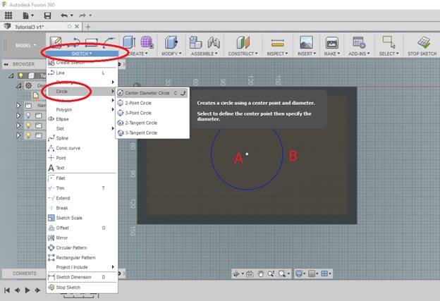
Click [Sketch] on the Ribbon Menu, and select the BOTTOM of your shelled cube.
Select [Circle] from the [Sketch] Ribbon Menu.
Start the circle at Point A, and click Point B to complete the circle as shown below. We’ll get it centered next.
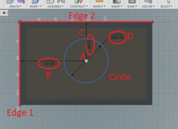
Now we will set dimensions. Type D, and follow the steps below.
-
- Click point A and Edge1, then click point B to place the dimension.
- Click point A and Edge2, then click point C to place the dimension.
- Click the Circle, then click point D to place the dimension.
- Modify dimensions to match those shown below if necessary
Click [FINISH SKETCH].
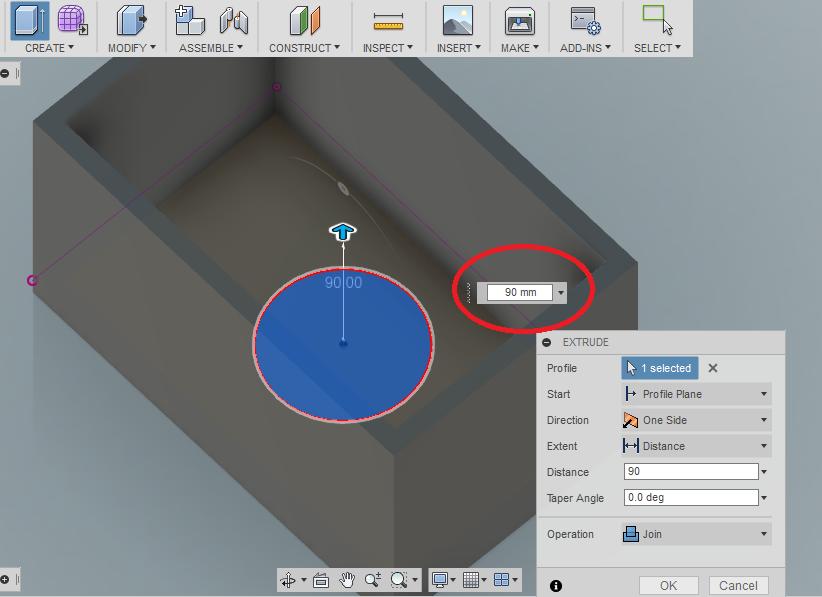
Type E to [EXTRUDE] Click the Inside of the Circle you just drew, and enter extrusion depth as 90, and click OK.
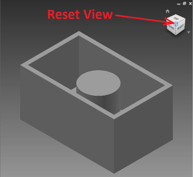
Click the Top/Front/Right corner of the View Cube to reset to an Isometric View. You should see this:
Using Work Planes to Create a Rib
When you first started building this object, you drew off of Work Planes. These planes referenced X, Y and Z. We can ADD our own work planes to aid on constructing elements of our object. There are many ways to create Work Planes, depending on what you need to build.
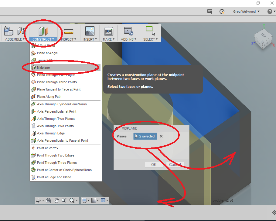
From [CONSTRUCT], pick Midplane, then select the two inside surfaces of the shell (you may need to hold [SHIFT] down and rotate the view by holding the [MIDDLE MOUSE BUTTON]. This will define references for the work plane so that the plane knows where to go. You can see the new Work Plane shown in yellow, below.
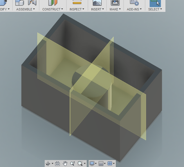
Do the same thing again, but to an adjacent side so it looks like this:
To add a rib, we need to have a sketch of what it is going to look like. Select [SKETCH] from the Ribbon Menu.
Select the longer of the Work Planes you created. Once you enter the Sketcher, you will need to see inside.
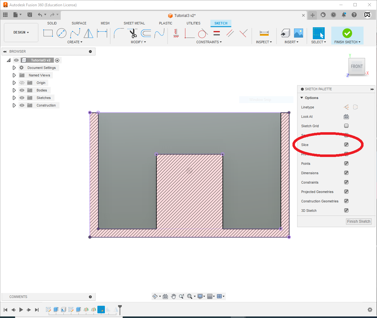
On the SKETCH PALETTE, click [Slice] (I also turned off SKETCH GRID, because honestly, I hate grid and never use it; it gets in the way. I also turned off Snap. I hate Snap too – I find it annoying at this stage.)
You should see this:
Fusion only knows that you want to Sketch on a Work Plane. This new plane has no idea what already exists. We want to “project” the “geometry” of existing parts into our Work Plane. To do that, click [Project/Include] from [CREATE] on the Ribbon Menu (you can also just type P) and click any edges you think you need to reference (you can see them in purple, below) – don’t worry about clicking too much, it will work out.
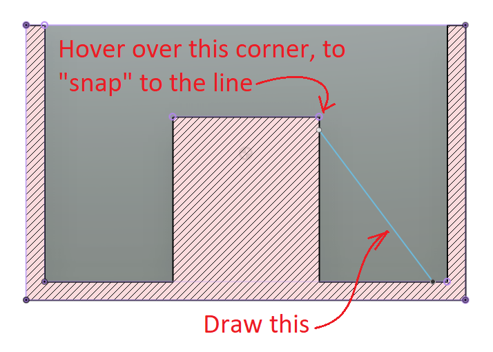
Now, lines you draw will “follow” the Geometry we Projected. Sketch the rib profile as shown below (in green), and click [FINISH SKETCH] to finish.
You can UNCHECK [SLICE], so make it a full shape once again (I’m in a “wire frame” view below).
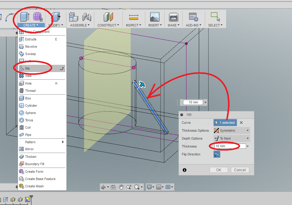
Select [Rib] from [CREATE] on the Ribbon Menu, and select the profile you drew, and tell Fusion that you want the rib to be symmetric, run down from the profile, and be 10mm thick. You should see this:
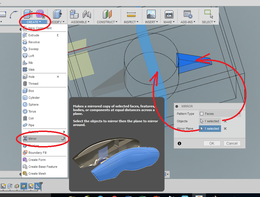
Add a second rib by using the [Mirror] under [CREATE] on the Ribbon Menu (mirrored off a Work Plane). You should something like this:
Ta-Da!
Select [Save] from the menu bar to save the part.
WANT IT MARKED?
Use the SNIPPING TOOL to do a WINDOW screen capture, and save the file into the HANDIN FOLDER with YOUR NAME and TUTORIAL/PROBLEM NAME (ie: wellwood-tutorial-1.png)
Now complete Problem 3.