
Tutorial 7: Lofts
Sweeping and lofting are useful techniques for designing parts which may be difficult to model with extrusions or revolves. Unlike those other modeling techniques, sweeps and lofts allow for parts with varying cross-sections and parts that twist or bend. In this section, you will create a vase using a loft.
Think of a LOFT as an EXTRUDE that CHANGES CROSS-SECTIONAL SHAPE.
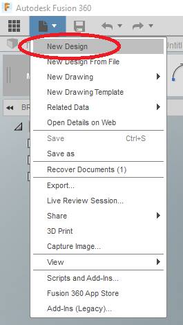
Click NEW DESIGN from the FILE icon at the top of your screen….
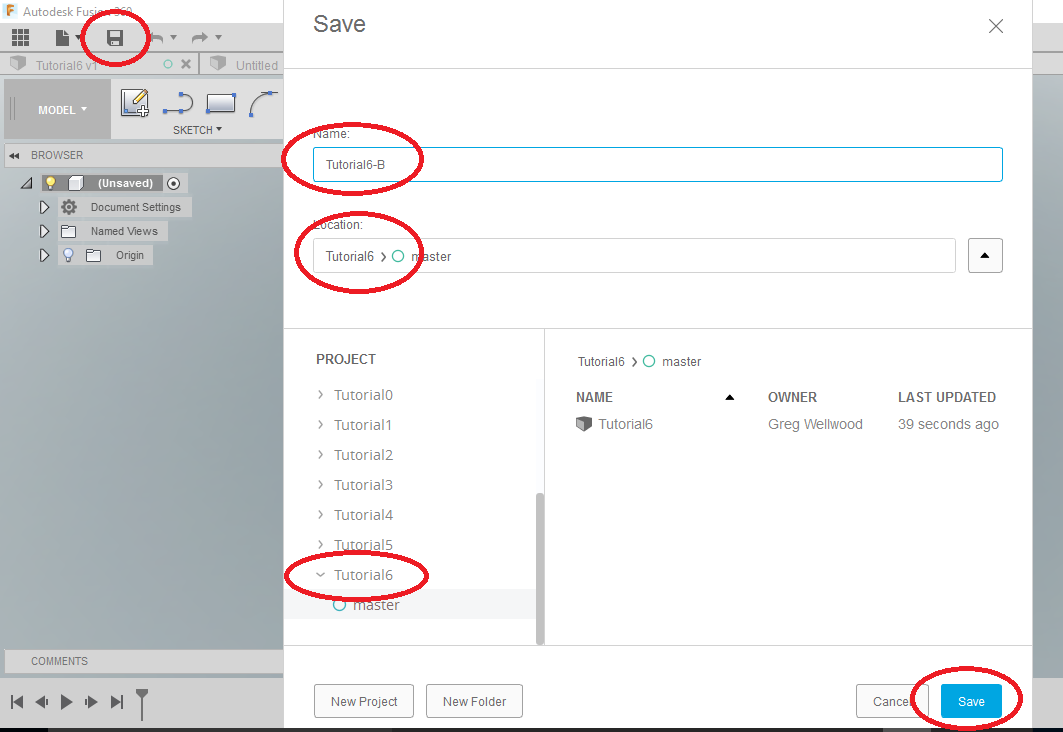
Name this new file Tutorial7 and save it in the FOLDER Tutorial7
We are going to draw a series of shapes on a series of Planes. Fusion will “connect” the profile of these shapes into a solid.
First, we are going to create the planes.
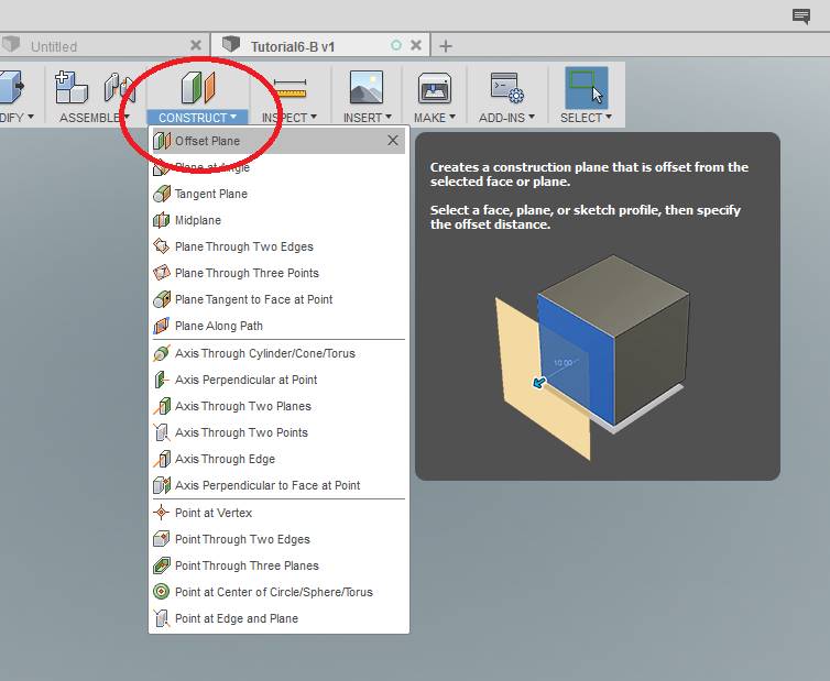
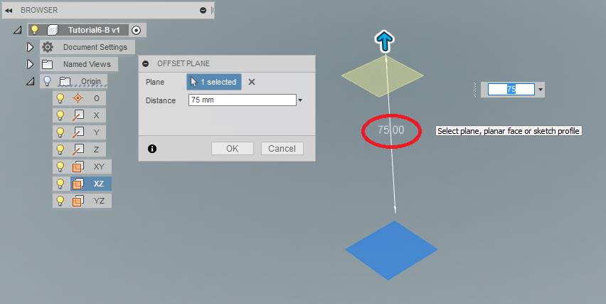
Select OFFSET PLANE from the CONSTRUCT Tab of the Ribbon Menu.
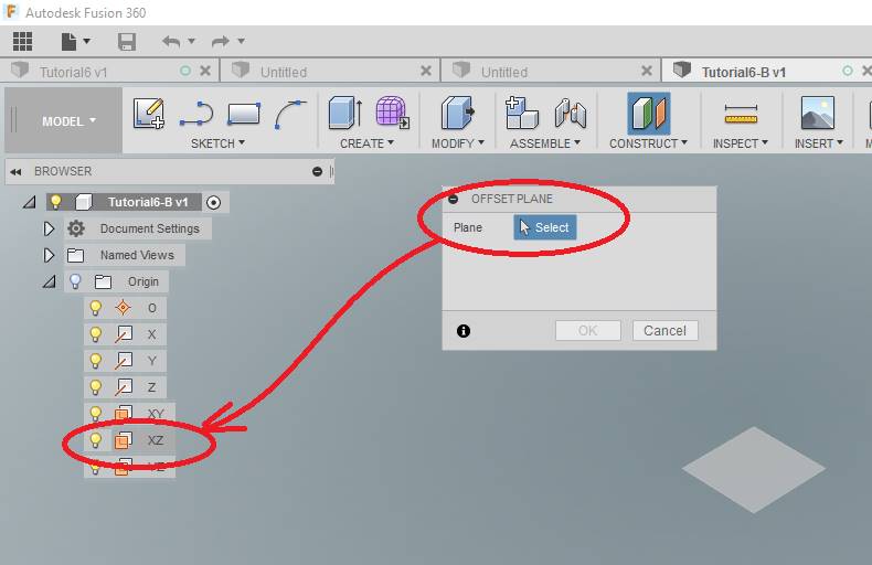
Pick the XZ Plane from the BROWSER, since that existing plane will not be visible.
Enter a DISTANCE of 75mm for the location of the new Plane. This will show up as Plane1 in the Timeline at the bottom of your screen.
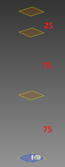
Add another Plane 75mm above your new one, and another Plane 25mm above that. Like so:
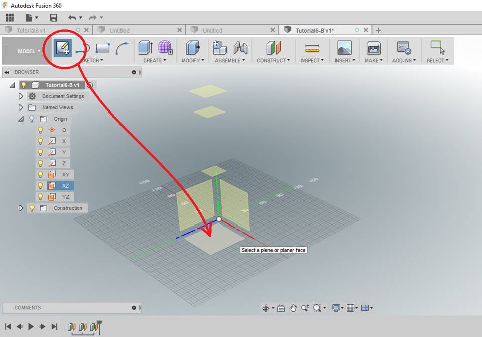
Click CREATE SKETCH from the SKETCH Tab of the Ribbon Menu, and select the Origin XZ Plane
SKETCH a circle with a diameter of 40mm

Create a 60mm circle on Plane1 (Try to reference the original circle center for these)
Create a 30mm circle on Plane2
Create a 50mm circle on Plane3
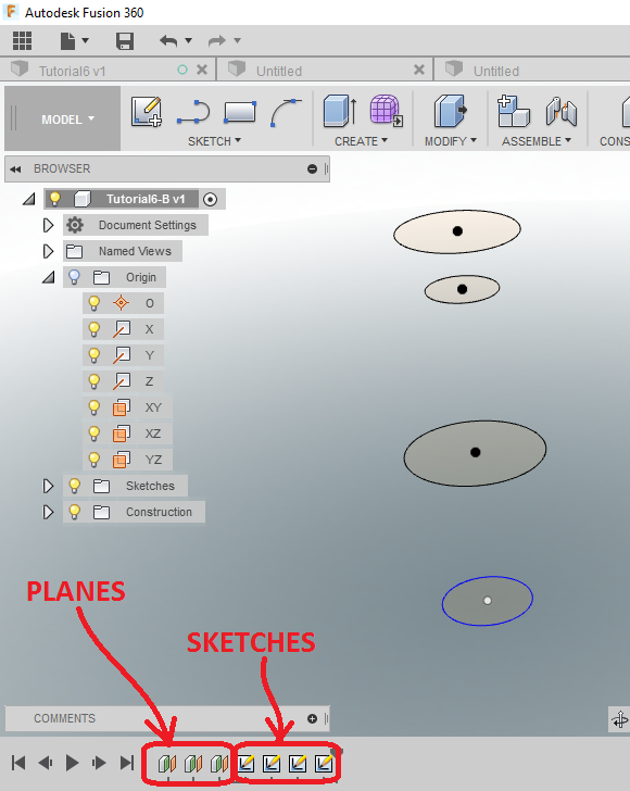
You should have something like this:
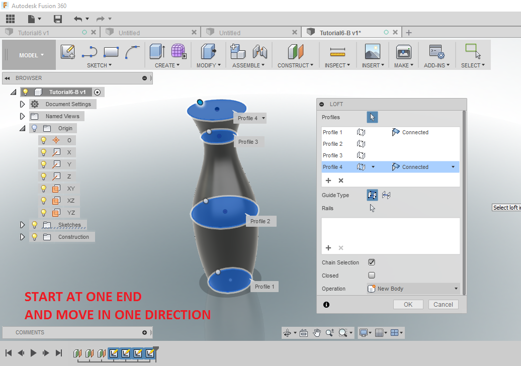
Click LOFT from the CREATE Tab of the Ribbon Menu

Starting at the BOTTOM circle, select all the circles in order from bottom to top. Fusion will create a solid using those surfaces. You should see this:
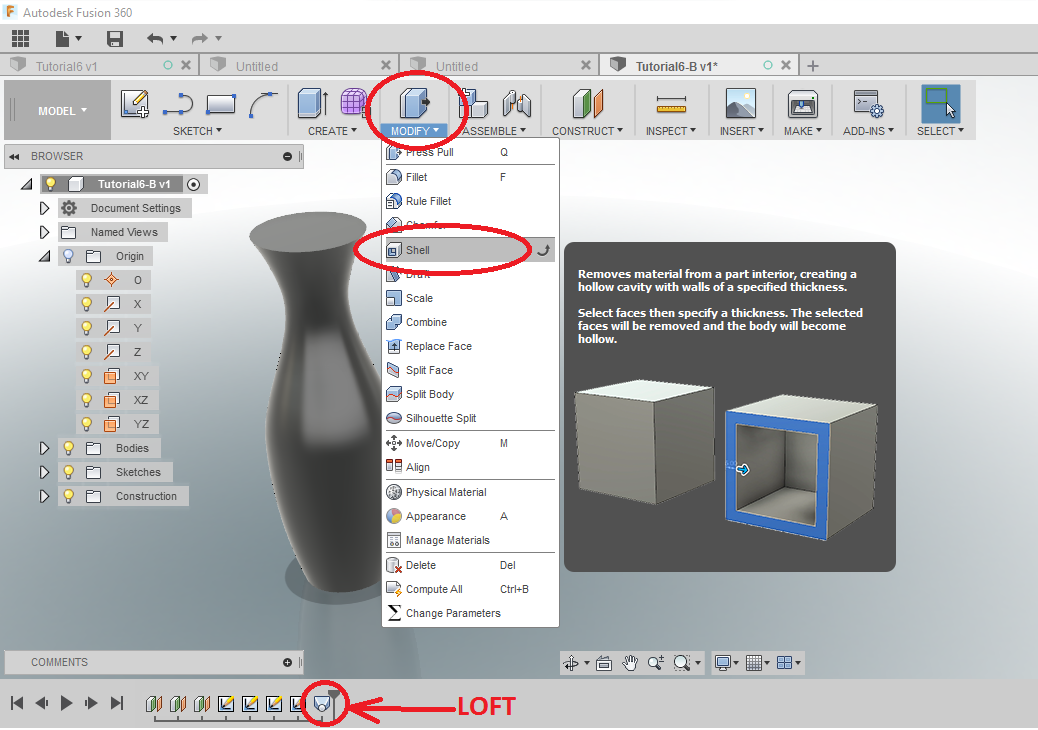
Use SHELL from the MODIFY Tab of the Ribbon Menu to make this vase a more usable vase.
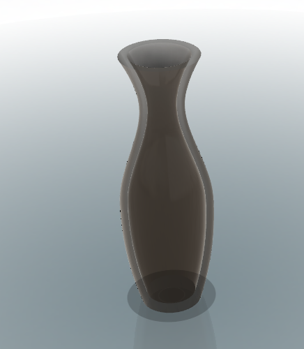
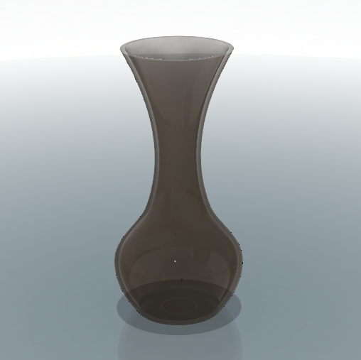
You can totally change the shape of your part by simply changing the distances between the Planes, Fusion will adjust the object.
WANT IT MARKED?
Use the SNIPPING TOOL to do a WINDOW screen capture, and save the files into the HANDIN FOLDER with YOUR NAME and TUTORIAL/PROBLEM NAME (ie: wellwood-tutorial-7.png)
Now complete Problem 7.