Tutorial 8: Engineering Drawings
Introduction
Engineering drawings are critical for communicating design ideas. Fusion’s drawing mode allows a user to create detailed drawings of previously created parts and assemblies. In this tutorial, you will learn the fundamentals of drawing mode while creating an annotated multi-view drawing of a part.
If you have ever made something from plans, you are at a distinct advantage because you know what you need to know to build it.
Creating a Drawing
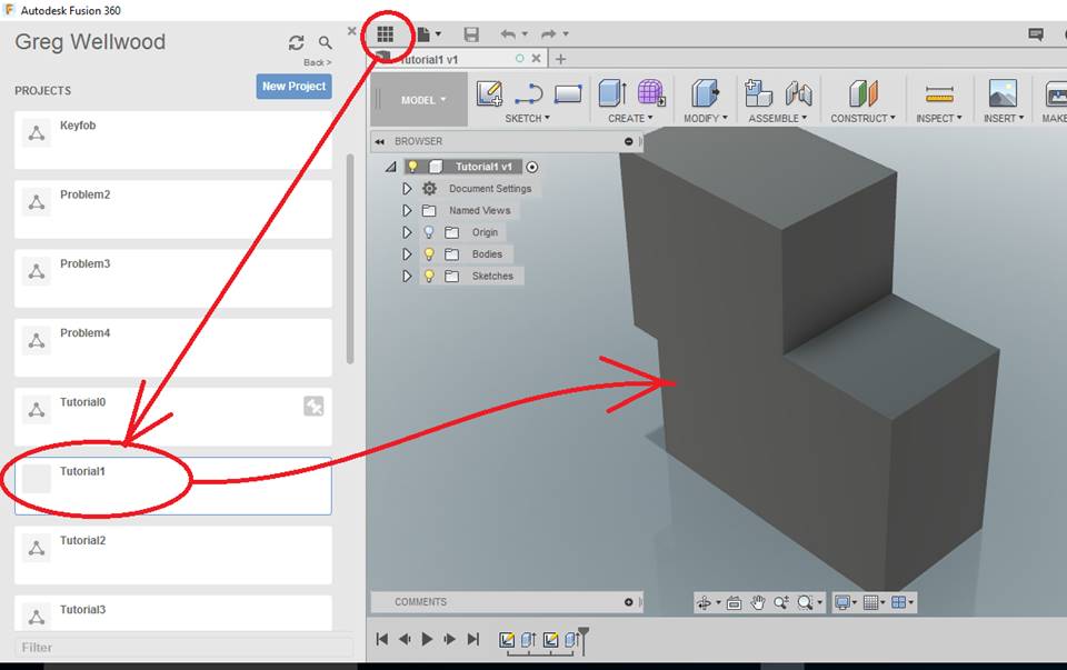
Open the TUTORIAL1 that you did, way back at the start. Click the stack of nine squares to find your projects.
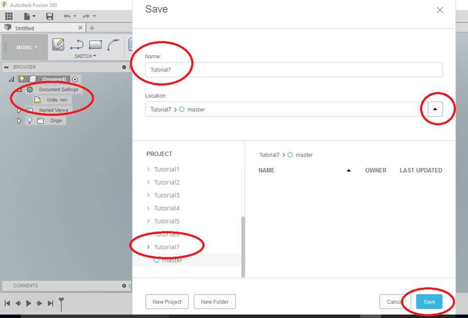
Select the SAVE Icon, select SAVE AS, and create a [NEW PROJECT] folder named “Tutorial8“, and from the BROWSER make sure it is [Units: mm].
YOU MUST KEEP YOUR FILES ORGANIZED! FOLDERS, NAMES, and LOCATIONS ARE IMPORTANT TO KEEPING YOUR FILES ORGANIZED!
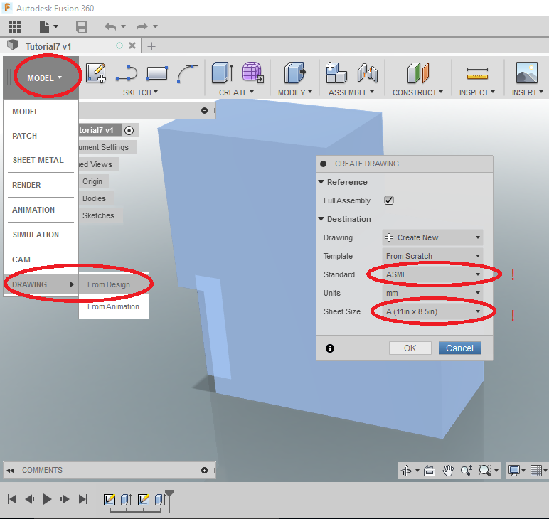
From the DESIGN tab of the Ribbon Menu, select DRAWING and then FROM DESIGN. Fusion will HIGHLIGHT the object, and pop up a menu: select Standard: ASME and Sheet Size: A (11in x 8.5).
Again: ASME & A (11×8.5)
I’m looking at you: kid not reading the tutorials
Look at your neighbor – if they skipped this step, it’s going to go bad for them later. Laugh now, because it’s going to get funnier.
GIVE THE PERSON NEXT TO YOU A WET WILLY if they actually picked ISO and/or A (8.5 x 11).
Give yourself two if YOU chose ISO or A (8.5 x 11).
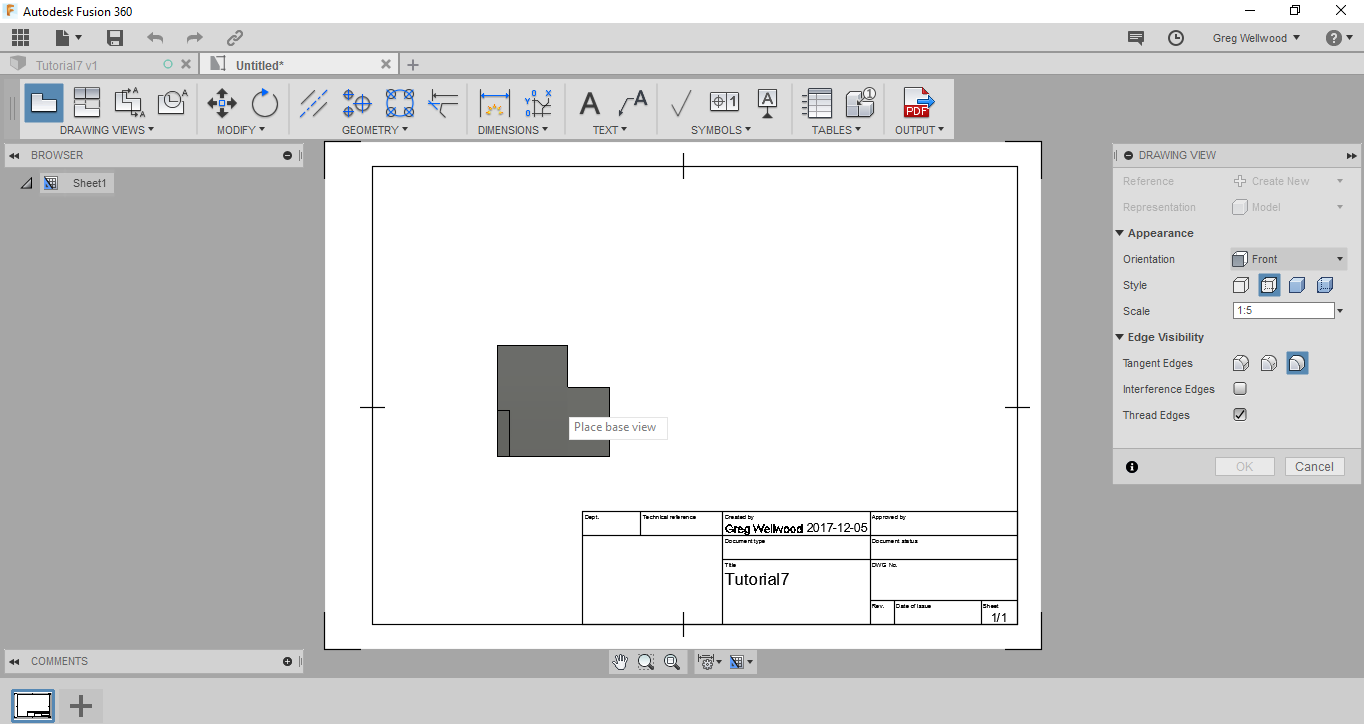
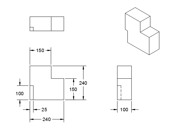
Click OK and a blank paper will show up. If you click on the lower left of the sheet to place the BASE VIEW, the front view of your object will appear. Fusion will likely adjust the scale so that the entire drawing will fit. If not, you can change it in the DRAWING VIEW menu. Ensure STYLE is set to VISIBLE AND HIDDEN EDGES since that is what an Orthographic Drawing shows.
If your paper is in PORTRAIT instead of LANDSCAPE as shown, lean over to the person next to you, and say “you have my permission to give me a WET WILLY.”
NOTICE THAT PLUS (+) SIGN AT THE BOTTOM LEFT, NEXT TO THAT SHEET OF PAPER ICON?
That’s where you can ADD another sheet – you do that when you are doing multiple parts of an assembly; each PART gets its own page.
You’ll need this knowledge for the 3-PART CHALLENGE!
You can adjust the location of this view at any time.
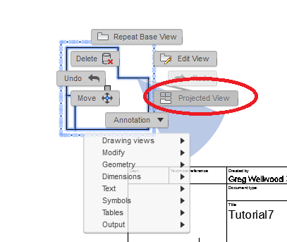
Click ONCE on your BASE VIEW, and then right click and select PROJECTED VIEW.
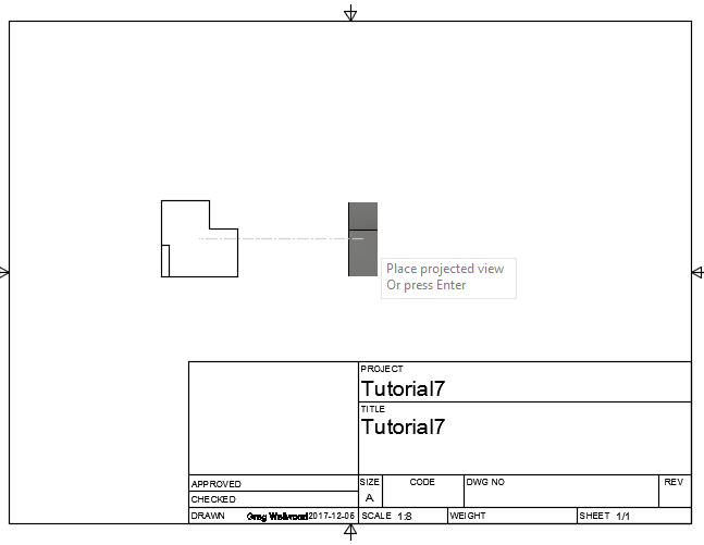
Drag the view off the side it needs to be. Try to keep the views equally spaced on the page (same amount of white space between the border and the views). You should do a SIDE VIEW and a TOP VIEW. I like to add an ISOMETRIC VIEW in the top right to show a more realistic view of what the object is.
If your friend’s views are projecting the wrong sides, laugh at them again, and say “ISO SILLY ASME!”
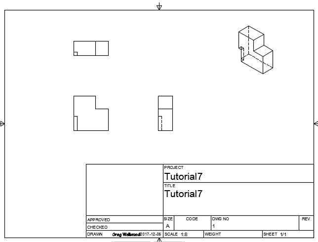
You can move any of the views by merely clicking and dragging them. Try to keep them equally spaced; we want “pretty.”
We can scale the drawing to any size we like (just double click the base view and change the scale), but DO NOT CLUTTER YOUR DRAWING
Next, we are going to add dimensions
Adding Dimensions and Tolerances
You will get better at dimensioning WHEN YOU ACTUALLY WORK OFF DRAWINGS TO BUILD SOMETHING
ENGINEERS and FABRICATORS have to work together. Just because it can be designed, DOES NOT mean that it can be built. I cannot machine a hollow object. I can only weld what the welding torch can reach.
The guys on the welding shop floor, or on the construction site, have a WEALTH of information that will BENEFIT YOU when you want design things.
I DO NOT want an engineer who HAS NOT BUILT anything.
From the DIMENSIONS tab of the Ribbon Menu, select the Sunshiney Dimension icon. Or just type D. You can click LINES or ENDS OF LINES to get the dimensions you need.
RULES:
-
- Dimension as much as you can on one view only
- Add only what you could not show on the main view to the best view to that would show clearly
- As much as possible, keep one view free of all dimensions
- Extension lines must have space between themselves and the edge they are measuring
- Dimension to corners are best
- Dimension to lines if you have to
- Dimension to hidden lines make me want to vomit the broken dreams of unicorns – don’t do it.
- NO dimensions sitting ON the object!
- Overall dimensions are the furthest outside
- Keep dimensions in a nice even line with each other (Fusion “SNAPS” these, which is super helpful!)
- TIDY TIDY TIDY – this is as much an Art as it is a Science.
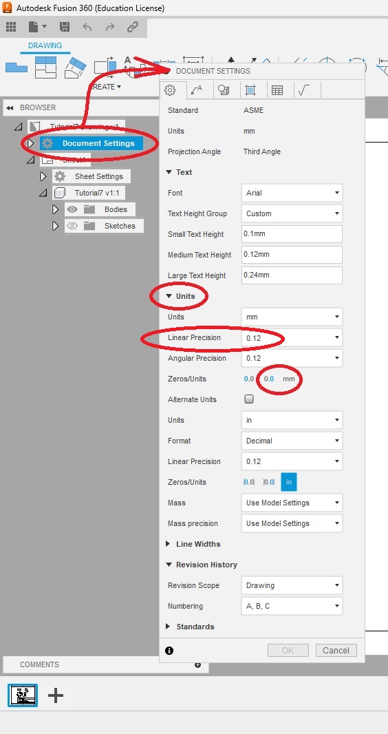
CLICK on DOCUMENT SETTINGS at the top of your BROWSER WINDOW, click on the gear that will show up on its right. Here we can GLOBALLY change dimension settings. Change LINEAR PRECISION to TWO DECIMAL PLACES (.12mm) and click DISPLAY TRAILING ZEROS. This sets a certain level of precision. When you write “240” it could be 240 plus or minus a little bit (as much as 0.500!). When you write 240.00, it could be 240.00 plus or minus a little bit (like 0.005); MUCH more precise.
There is a place for high levels of precision: Heart valves; Space Shuttles; Nuclear Reactors.
There is a place for low precision: Shelves; Door stoppers; Fence posts; The crew that built my house.
A machine shop can fabricate your door stopper to four decimal places, it will take a long time to make, and it would cost a fortune, but it would be PERFECT. As an aside:
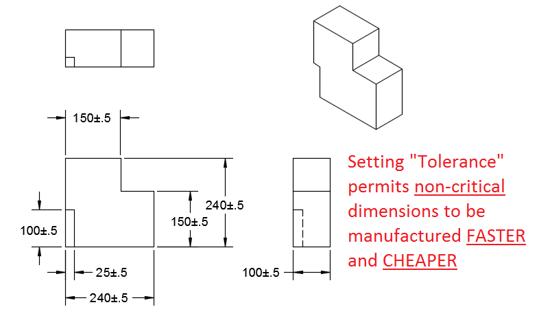
A fabrication shop will want to know what is allowable. Sometimes a measurement can be BIGGER but it cannot be SMALLER. For these, we add TOLERANCE.
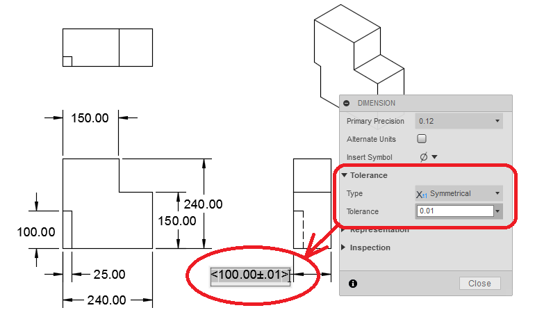
Double-Click the width dimension (the actual number between the arrows) of your END VIEW. Change the Tolerance to Symmetrical +/-0.01. This tells the builder how fussy they have to be. On some project parts in Metalwork, I tell my students “If you’re going to screw up, screw up longer, not shorter.” It’s faster to build (and thus cheaper to build) if you can “tolerate” a little “imprecision.”
We have now allowed the WIDTH of the object to be made as large as 100.01, or as small as 99.99. Truthfully, in metric, that precision is ONE-QUARTER THE THICKNESS OF A HUMAN HAIR. I assure you: that is an unreasonable tolerance for a part like this. Let’s change that.
Double-Click EACH of the dimensions and change them ALL to a tolerance of Symmetric +/- 0.5 (Yes – I turned off the Trailing Zeros for clarity).
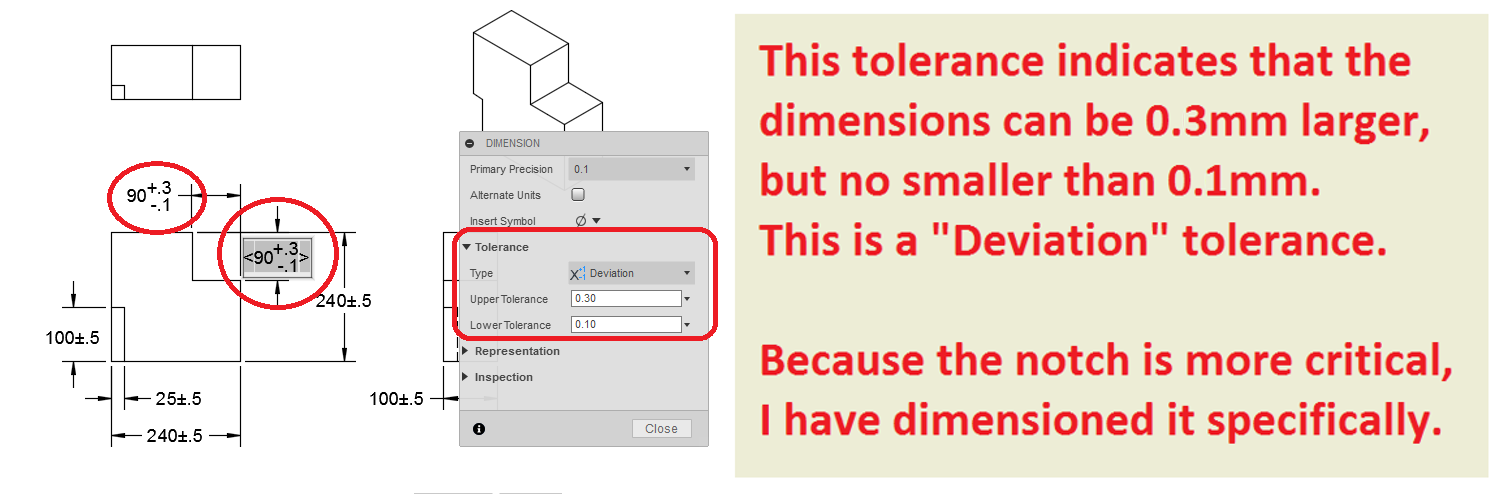
Sometimes not ALL the dimensions have to have the same tolerance. Sometimes I fabricate parts where the basic dimensions really don’t matter, but the location of two holes is critical. I would “call out” different tolerances as needed.
Let’s make the actual notch in the object more critical – notice how I have changed WHAT I DIMENSIONED in the view, as well as the TOLERANCE.
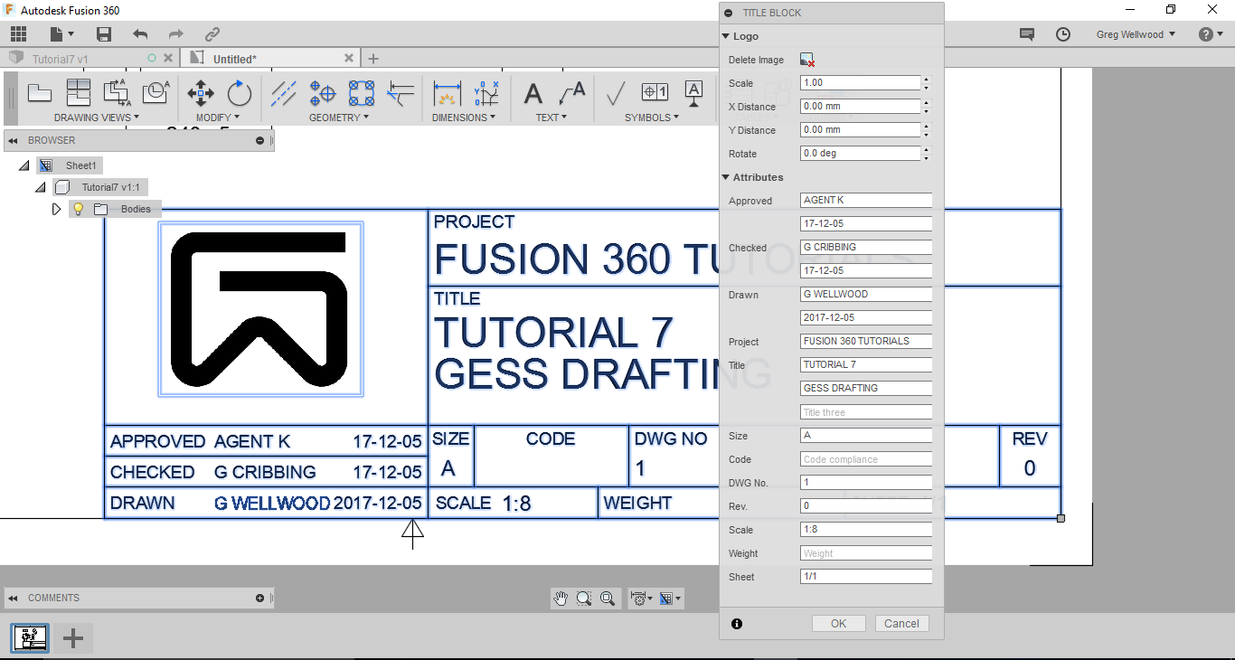
Creating Notes for Title Block
In this section you will fill in the title block of the drawing. Double-Click the Titleblock of your drawing, and complete the information as relevant to you.
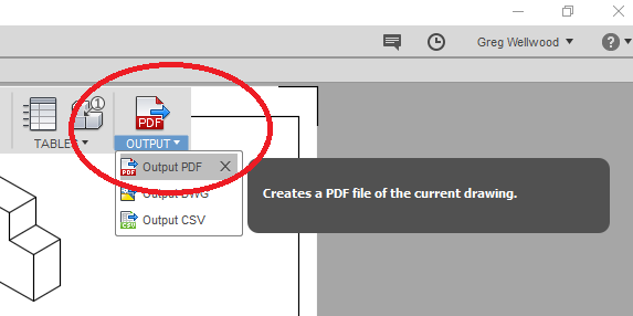
From the OUTPUT tab of the Ribbon Menu, click OUTPUT PDF to send your drawing into an Adobe PDF file. They usually show up in your DOWNLOADS folder.
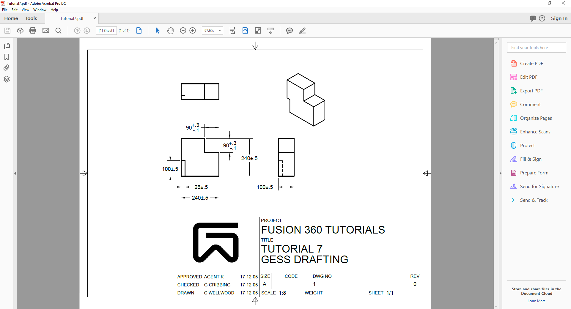
And you should now have something that looks like this:
WANT IT MARKED? SHOW ME ON SCREEN, THEN SAVE THE PDF TO THE HANDIN FOLDER
DO NOT GO ON WITHOUT ME CHECKING!
Now complete Problem 8.