
Tutorial 5: Revolves, Patterns, and Copies
Introduction
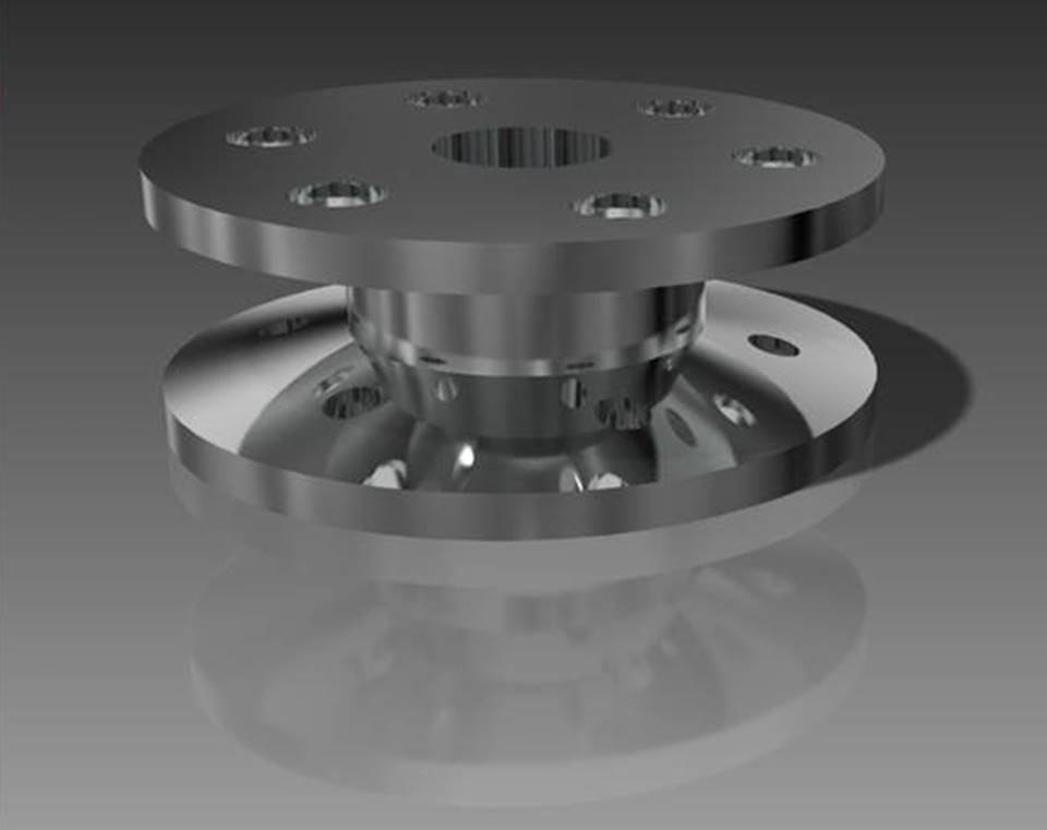
The Revolve option is useful for designing circular parts and features. Patterns and copies allow multiple instances of a feature to be created with little effort. In this section, you will revolve a section around a centerline to create a pulley and a hole. You will also create a pattern of holes and a copy of this pattern.
Creating a Revolved Part
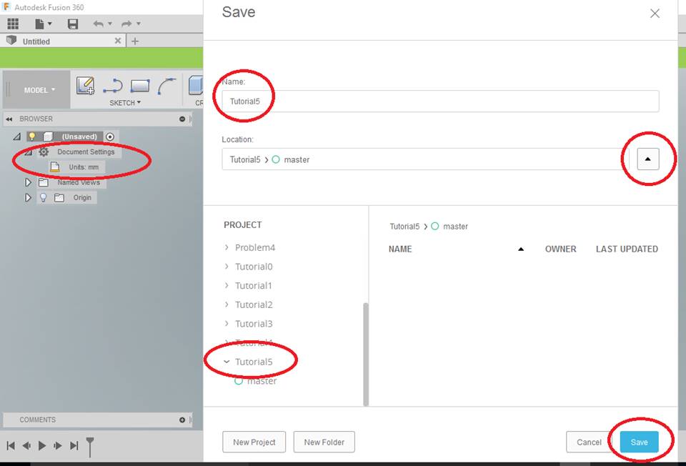
Start Fusion 360. Select the “Save” Icon, create a [NEW PROJECT] folder named “Tutorial5“, and from the BROWSER make sure it is [Units: mm].
YOU MUST KEEP YOUR FILES ORGANIZED! FOLDERS, NAMES, and LOCATIONS ARE IMPORTANT TO KEEPING YOUR FILES ORGANIZED!
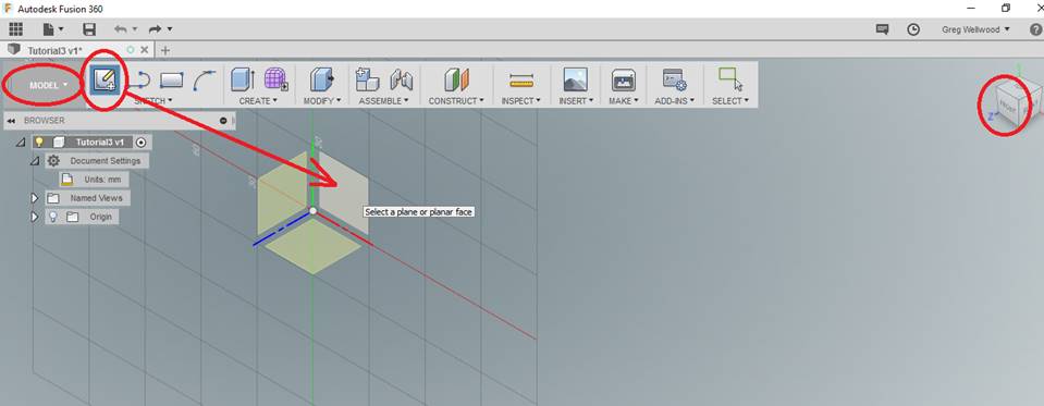
From [MODEL] tab on the Ribbon Menu, click [Sketch], pick the FRONT (x,y) plane and enter SKETCH
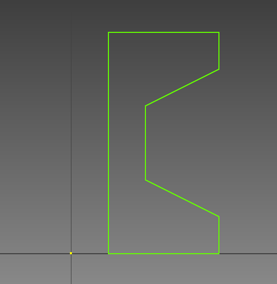
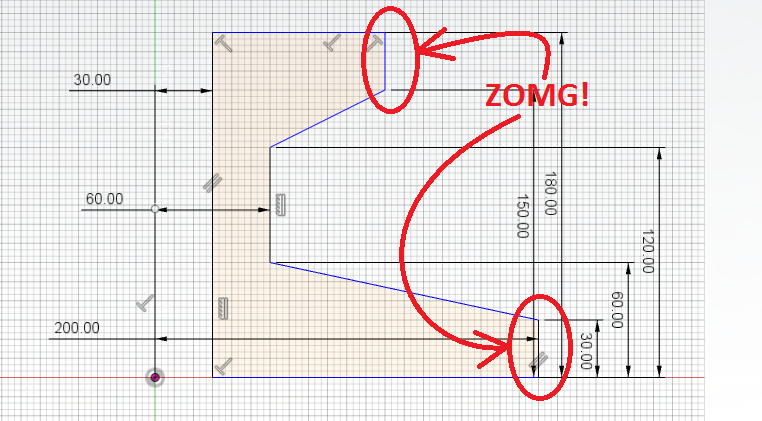
Sketch the image shown below. It does not matter at this point what the dimensions are, just make it look roughly the same.
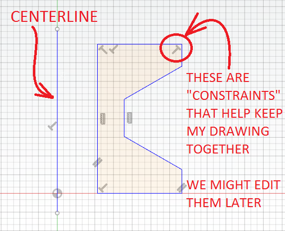
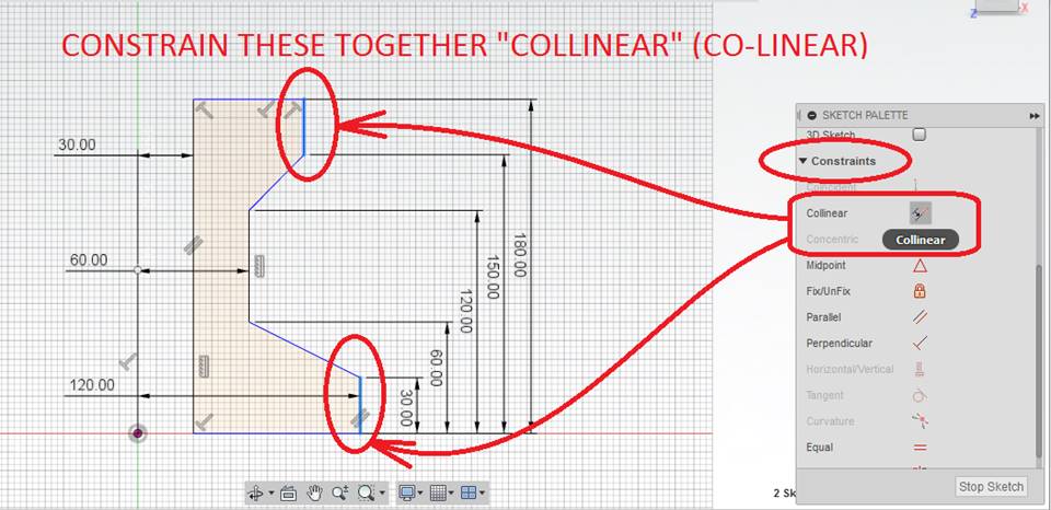
From the [Sketch] tab on the Ribbon Menu, select and draw a [Line] ON the Y axis for a “centerline” on the vertical axis. When you select this line as a Centerline during the Revolve command, Fusion uses it and then hides it for you. The object you drew will be Revolved around this Centerline.
Type “D” to Dimension your drawing as shown below. You can click each Vertices (corners) or actual Lines to create the dimensions. When you click a vertical edge AND the centerline, Inventor shows Radius.
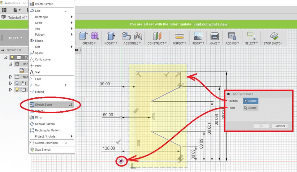
From [MODIFY] on the Ribbon Menu, select [Sketch Scale] , and drag a Crossing Box over your drawing (DO NOT select the Centerline).
-
- POINT: Select the (x,y) ORIGIN
- Scale Factor: Type 0.5 (to scale half size, or “50%”)
The entire drawing should now be half the size it was before.
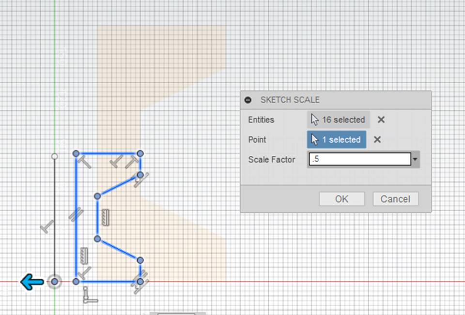
Cool eh?
Yeah, we don’t need this. Do a [CTRL-Z] to undo this and get back to the drawing you had. I’m just adding to your skill set in Fusion right now. Carry on!
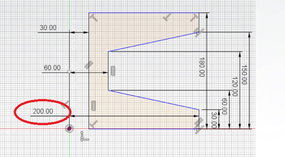
Double-Click the Ø120 dimension and change it to Ø200.
If you got the image below, you’re rockin!
If you got THIS IMAGE (BELOW) instead, you need to go back and add that COLLINEAR CONSTRAINT (YOU SKIPPED IT – IT WAS EXPLAINED ABOVE)
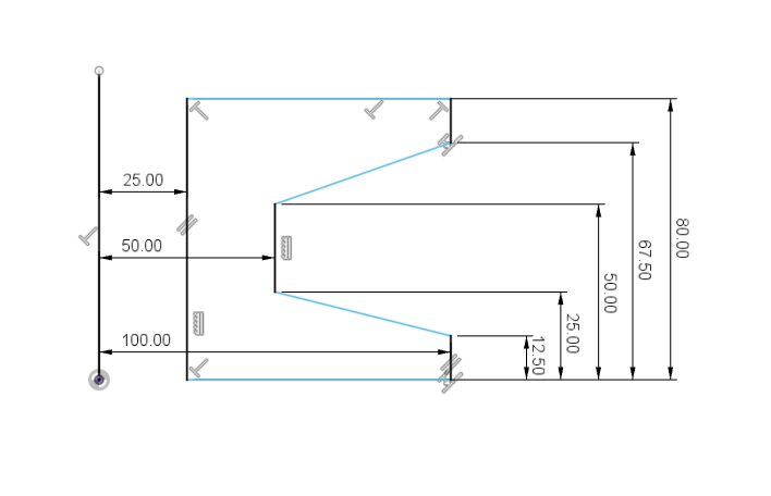
Now change all the dimensions as shown below. You can click them individually (slow) or you can scale them all (fast):
Finally, click FINISH SKETCH
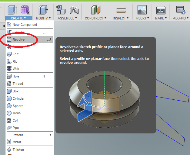
From the [CREATE] tab of the Ribbon Menu, click [Revolve].
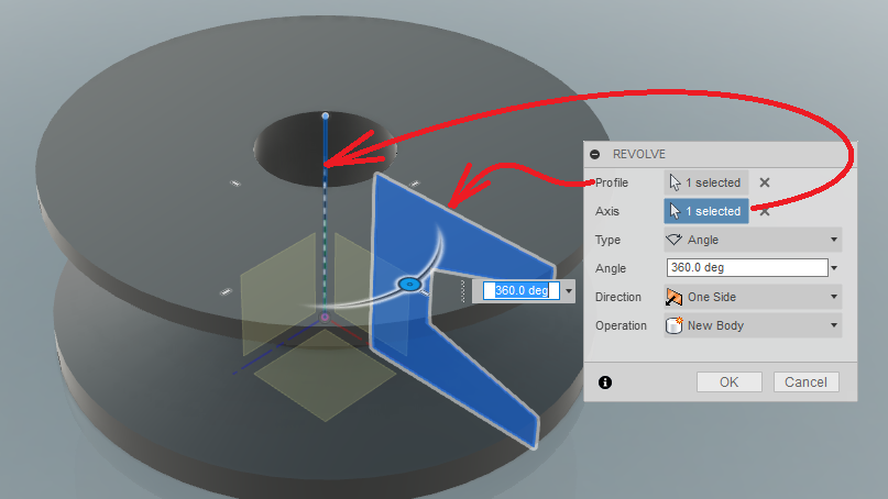
Pick the SKETCH and the CENTERLINE and watch Fusion do its magic!
I right-clicked on BODY1 in the BROWSER and edited the PHYSICAL MATERIAL and got this:
Creating a Sketched Hole by Revolving Section
We want to add a series of holes. We need to tell Fusion where to put them.
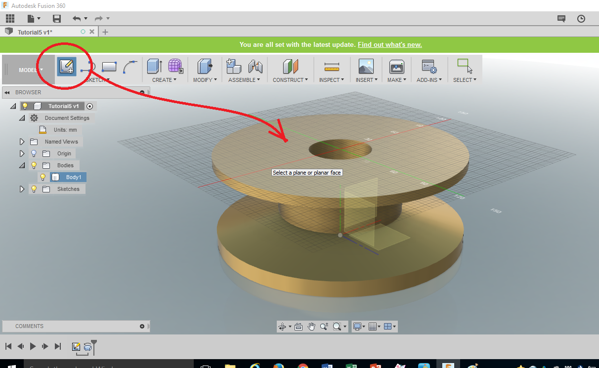
From the [SKETCH] tab of the Ribbon Menu, select [Create 2D Sketch], and then click the top surface of our Revolved Object.
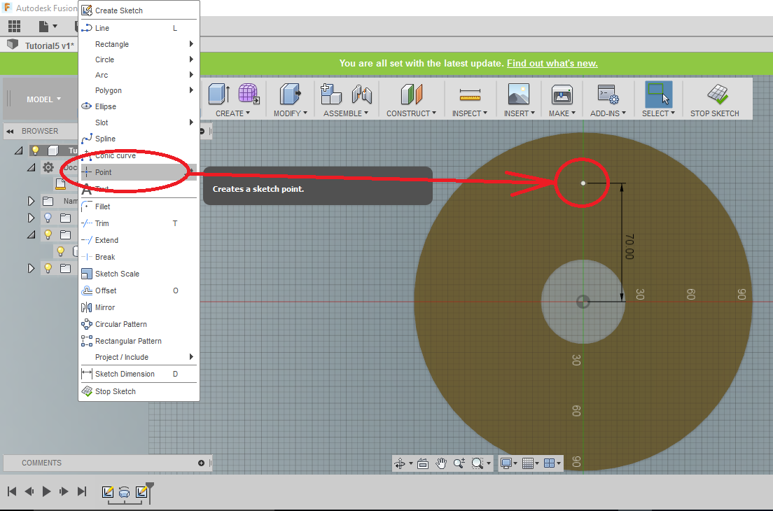
Once we are in Sketch, select Point, and place a point along the vertical axis (if your cursor does not “snap” or “constrain” itself to the Y axis, hover over the origin for a bit and it will). Then Dimension its location away from center as shown:
Click FINISH SKETCH.
From [CREATE] tab on the Ribbon Menu, click [Hole], and select the POINT you just sketched. Fusion will automatically place the hole there. Change the details of the hole as shown (newer versions of Fusion360 have renamed “Depth” to be “Extents“).
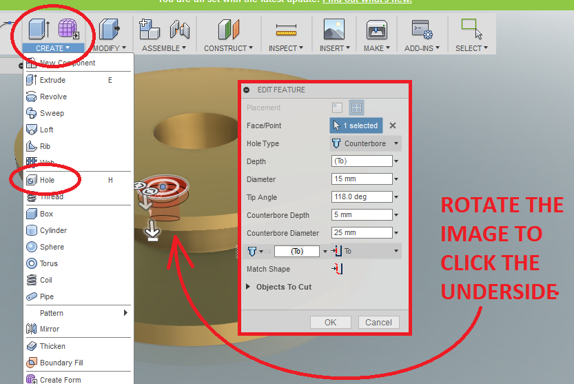
Note: Setting the hole depth “TO” the underside didn’t work for me in the 2019 version of Fusion360 and I couldn’t figure out why. In that case, I just pulled the depth down to make sure it cut all the way through.
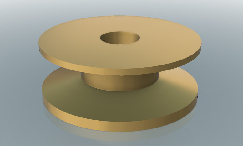
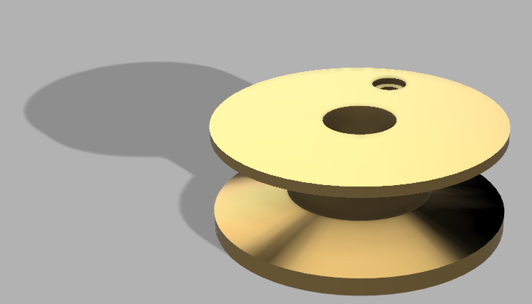
Have a look at your handiwork before you continue. How’s shiny brass grab you??
Creating Patterns and Copies
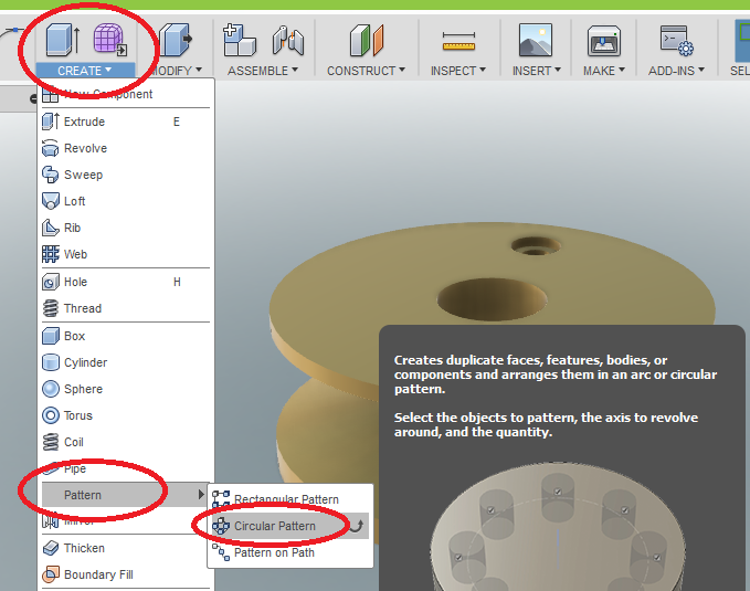
From the [CREATE] tab of the Ribbon Menu select [Pattern] and then [CIRCULAR]
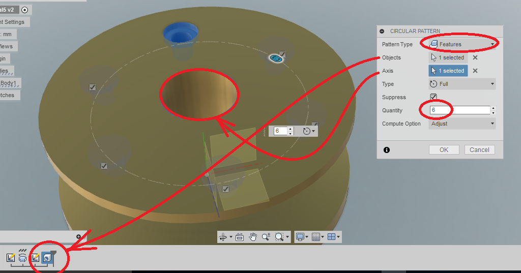
On the Circular Pattern Pop-Up, click Pattern Type: Features and select the hole you just created off the TIMELINE at the bottom of your screen. For Rotational Axis select one of the revolved surfaces because they have a Centerline in their creation. Pattern 6 holes, so it looks like this:
We want to mirror these holes onto the opposite side, so let’s set up a Mirror Plane.
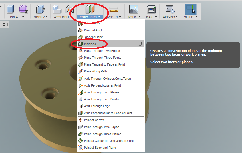
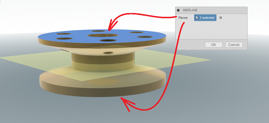
From the [CONSTRUCT] tab on the Ribbon Menu, click the Midplane. Click the TOP and BOTTOM flat surfaces of the object, and a new plane should pop up right in the middle.
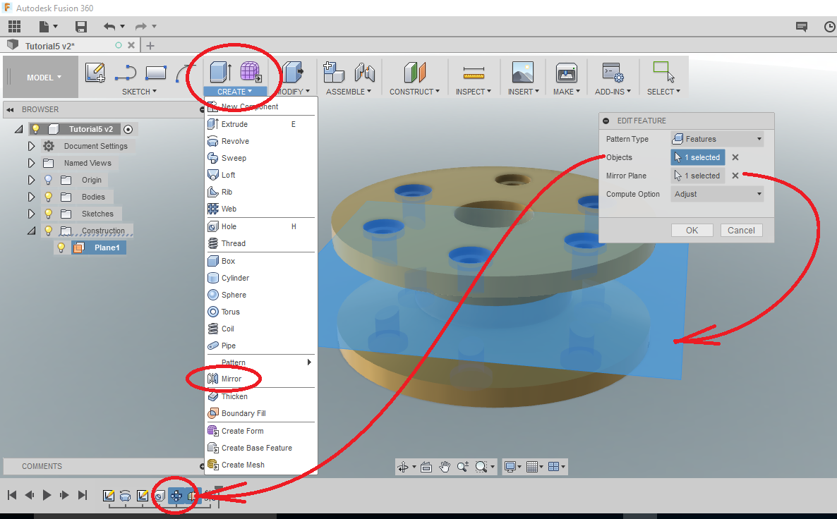
Using the [CREATE] tab of the Ribbon Menu, select [Mirror]. Select your CIRCULAR PATTERN of holes, (make sure you pick “FEATURES”) and then select the Midplane we just created. We should see the holes mirroring. You might need to change from “ADJUST” to “OPTIMIZED”
WANT IT MARKED?
Use the SNIPPING TOOL to do a WINDOW screen capture, and save the file into the HANDIN FOLDER with YOUR NAME and TUTORIAL/PROBLEM NAME (ie: wellwood-tutorial-1.png)
Now complete Problem 5.