
Tutorial 2: Holes, Fillets, and Chamfers
Introduction
A variety of geometric shapes and constructions can be designed automatically with Inventor, including holes, fillets, and chamfers. The Hole option creates many types of holes, including straight holes, sketched holes, and holes for standard fasteners. The Fillet option creates a fillet or a round on an edge that is a smooth transition with a circular profile between two adjacent surfaces. Point this sentence out to your Instructor. The Chamfer option creates a beveled surface at the intersection of edges.
Creating Base Shape
Start Fusion.
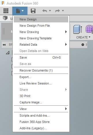
From the “FILE” Icon, select [New Design] .
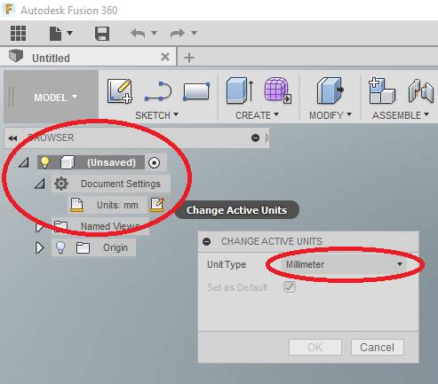
In the Project BROWSER, select [Document Settings], pick [Units] and confirm that you are in Millimeter. Click OK or CANCEL as needed.
SAVE the part as “Tutorial2”.
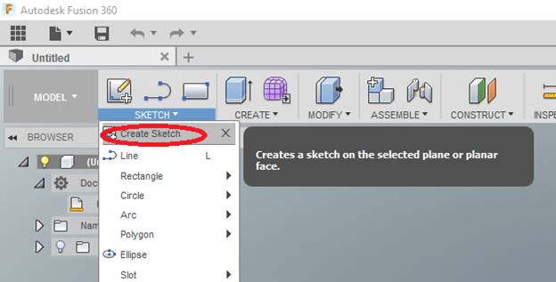
Select [Create Sketch] from the SKETCH section of the Ribbon Menu at the top of the screen.
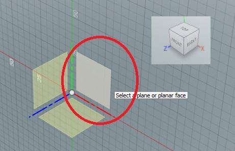
Select the XY Plane. Fusion will enter Sketch Mode. (Although, technically, it isn’t going to matter WHICH plane you select – it will all work out)
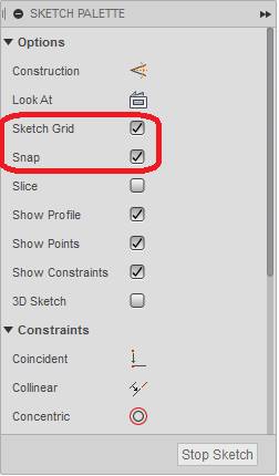
In this section, you will sketch the cross-section of the part using the same method as in Tutorial 1. The SKETCH PALETTE should have opened on the right side of your screen. Make sure [Sketch Grid] and [Snap] are checked (don’t worry about the rest).
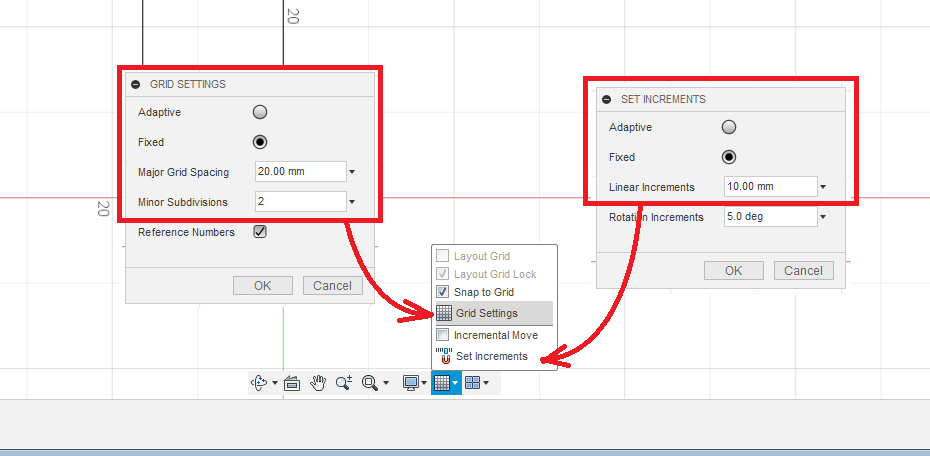
Go into the Grid and Snaps settings (shown below), and set the increment to 10mm. Also change the GRID SETTINGS to 10mm Major Grid Spacing, with 2 Minor Subdivisions.
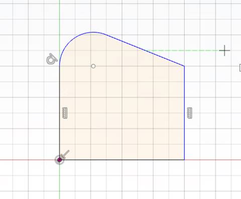
Now sketch the shape of the cross-section shown below. Follow the steps below:
-
- Select [Line] from the ribbon [SKETCH] menu.
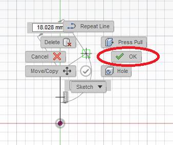
- Draw a line from the ORIGIN up six squares (60mm). Then press the right mouse button and select [OK].
-
- Select [Arc (Tangent)] from [SKETCH] menu.
- Click the top of the line you just drew, and draw an arc that ends UP 20mm and to the right 30mm. (Although technically, we’re going to dimension this next, so just make it look kinda like what you see here and don’t fret the details).
- Select [Line] from GEOMETRY menu.
- Complete the drawing as shown below, noting the number of grid squares
(if you did not change the grid settings above, this will be all wrong!)
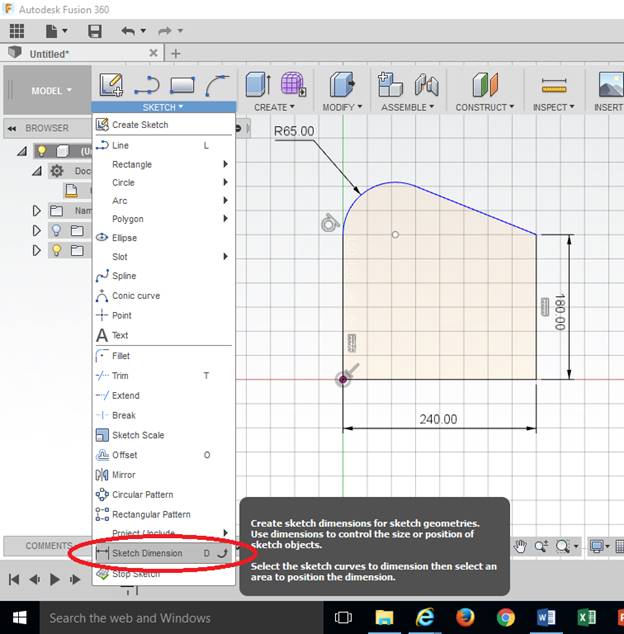
Now set dimensions as instructed and shown below.
-
- Select [Sketch Dimension] from [Sketch] on the ribbon menu. (for the lazy, just type “D” – you don’t have to click anywhere to type, Fusion just knows.
- Click the RIGHT VERTICAL EDGE with the left mouse button, and click a point off of your object with the left mouse button to place the dimension. If the dimension is not exact, you can type the number in and the lengths will adjust accordingly.
- Click the BOTTOM HORIZONTAL EDGE with the left mouse button, and click below the object with the left mouse button to place the dimension.
- Click the Arc with the left mouse button, and click to place the dimension.
NOTE: THESE ARE ALL THE DIMENSIONS YOU NEED TO FABRICATE THIS PART. NOT EVERY EDGE WILL BE DIMENSIONED
-
- Modify dimensions to match those shown in below if necessary.
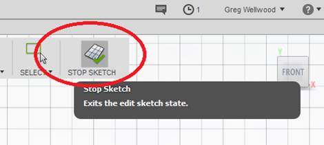
Select [STOP SKETCH] to complete the sketch.
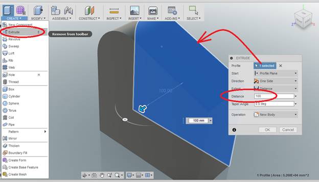
You should now have your sketch floating in space. From the [CREATE] tab of the ribbon menu select [Extrude], to a depth of 100, and click OK.
Creating Holes
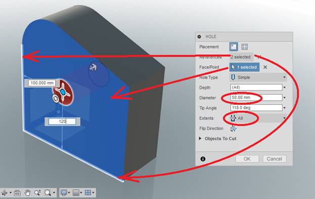
From the CREATE tab of the RIBBON MENU, select Hole.
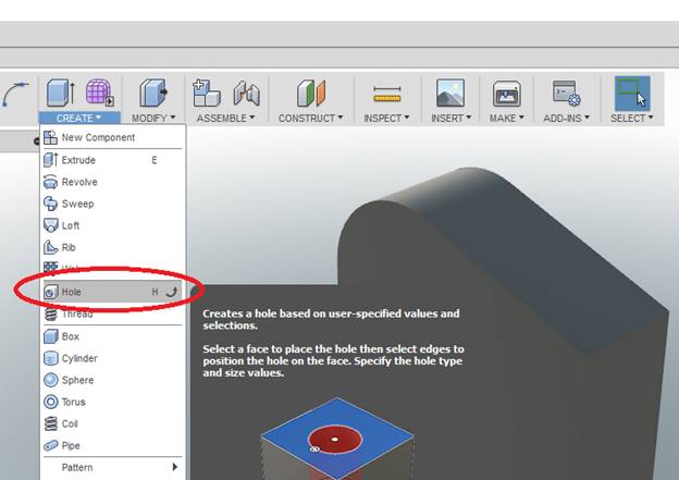
Holes need THREE REFERENCES to know where they go.
The hole MUST BE COMPLETELY REFERENCED (3 references)!
-
-
- Click the SURFACE where the hole is to go.
- Click an EDGE to be measured from.
- Click ANOTHER EDGE to be measured from.
-
Make the Hole Diameter 50mm, and the Extents of the hole All as shown:
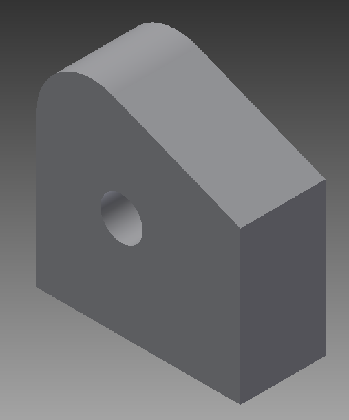
Click [OK], and the hole will be created as shown:
Edge Rounding and Chamfering
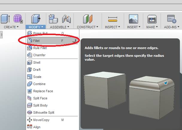
From the MODIFY tab of the RIBBON MENU, Select Fillet (Fill-IT, not Fill-AYE, it is not a fish). A brief description shows up to show you how to do things if you hover over the icon long enough.
Click Edge 1, Edge 2, Edge 3 and Edge 4 from Figure 2.9 with the left mouse button, setting the RADIUS to 10mm as you go.
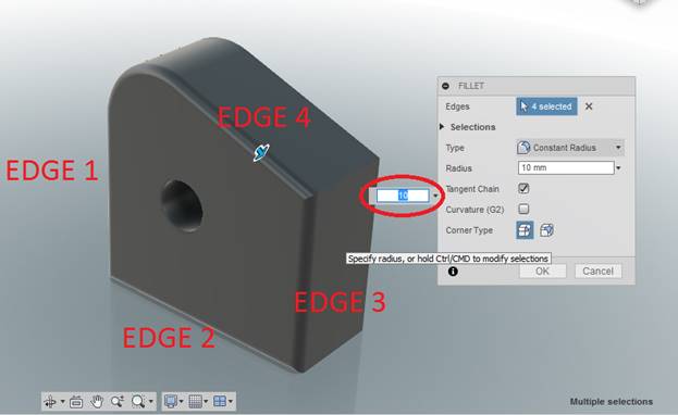
Click [OK], and you should see THIS.
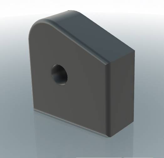
Now hit [CTRL-Z] on your keyboard to UNDO the fillet.
Go back to the MODIFY tab and select [Rule Fillet], only this time, only click the flat surface. ALL edges will be filleted simultaneously – this saves a lot of clicking (and mistakes)!
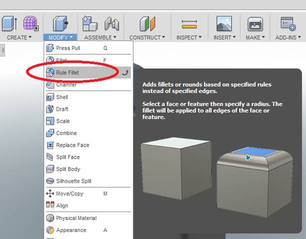
*NOTE: RULE FILLET has been deleted in newer versions of Fusion360. Instead, do this:
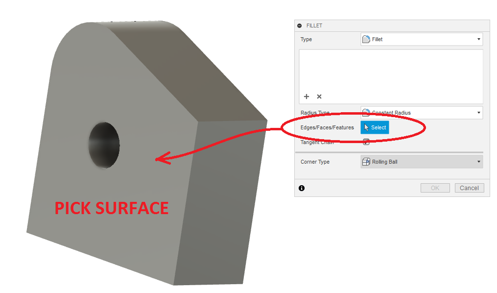
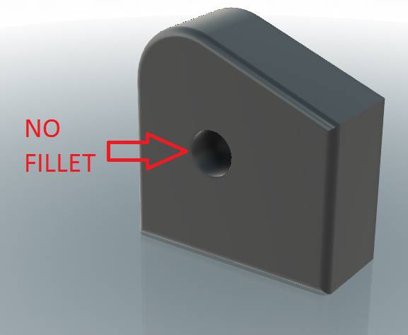
UH-OH! This filleted the hole, and we don’t want a fillet there. Click the fillet so it is selected, and hit DELETE on your keyboard. It should be gone.
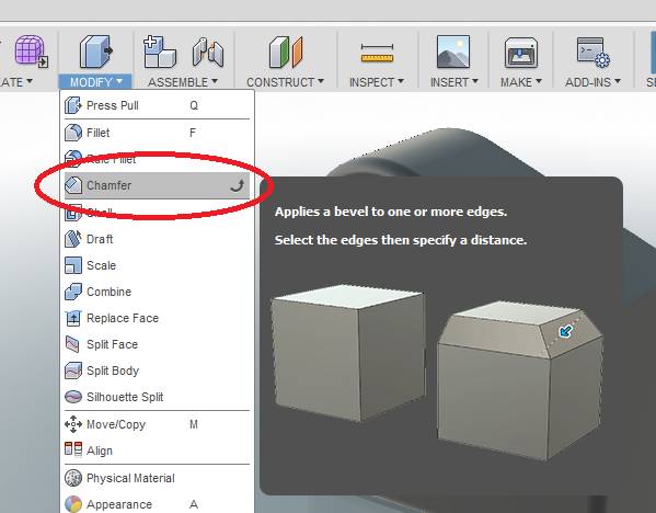
From the [MODIFY] tab of the Ribbon Menu, select Chamfer, as shown below.
Select the edge around the hole, and enter 10 into the textbox for the chamfer tool.
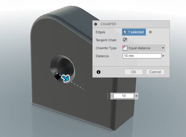
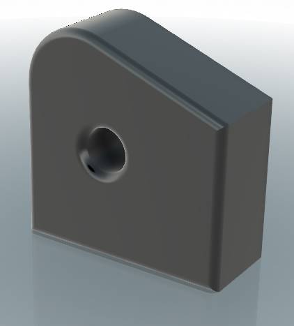
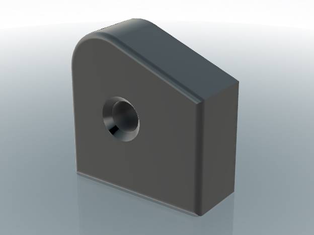
Select the edge around the hole in the part, and click [OK]. If you followed the directions correctly, you should see this:
Select [File] -> [Save] from menu bar to save the part.
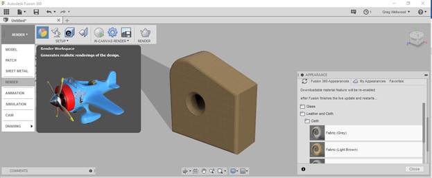
From the DESIGN tab on the ribbon menu, check out different RENDER settings. I tried a light brown fabric finish for this one:
WANT IT MARKED?
Use the SNIPPING TOOL to do a WINDOW screen capture, and save the file into the HANDIN FOLDER with YOUR NAME and TUTORIAL/PROBLEM NAME (ie: wellwood-tutorial-1.png)

Now complete Problem 2.