[ Start ] [ Index ] [ Parts List ]
In Which I Plumb the Turbo
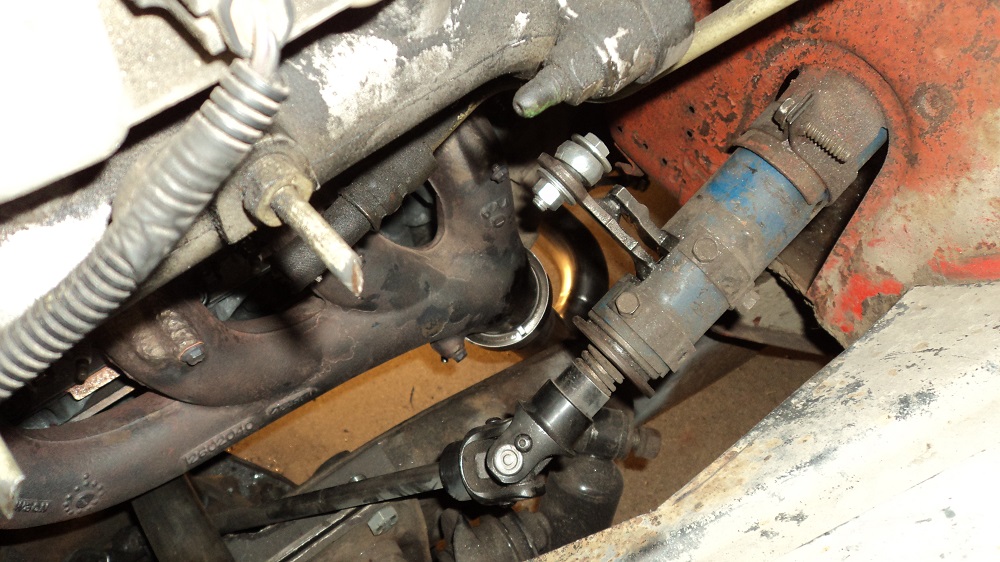
Exhaust will run from the driver’s manifold down and under the bellhousing, and up to meet the T4 flange at a flipped and upwards passenger manifold.
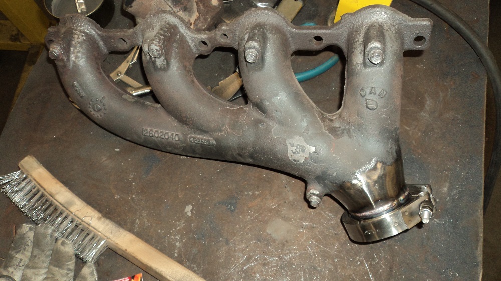
Turns out I didn’t cut the manifold at an angle for the v-band, and should have. So I cut it apart again and re-welded it.
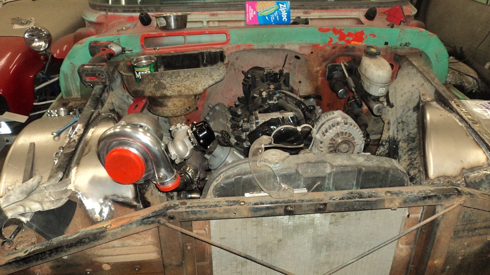
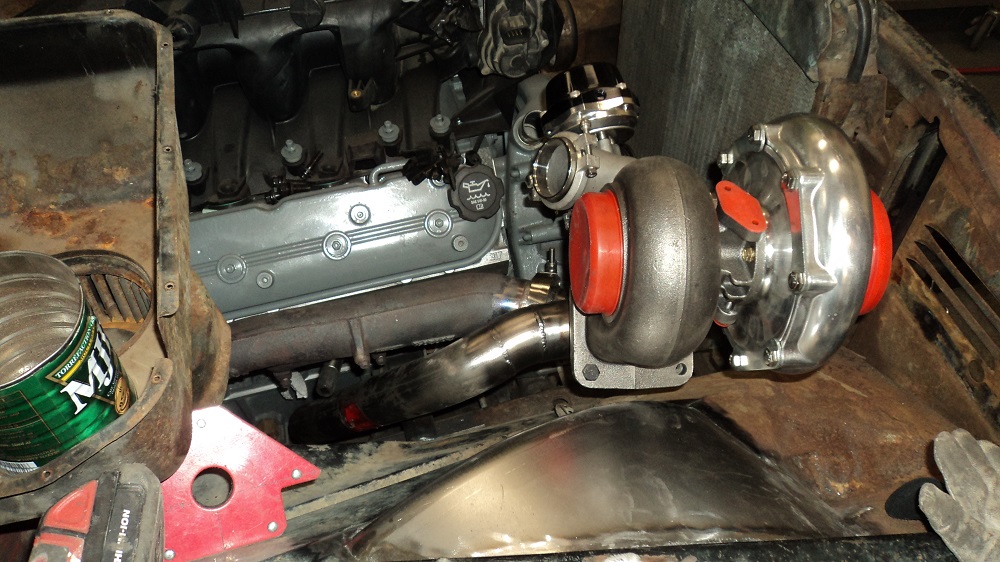
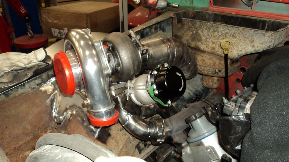
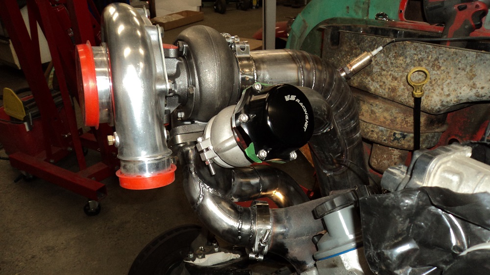
Then spent the entire rest of the day trying to devise a mount which would hold the turbo while I fabricate the pipes to run it. Trying to get the right placement so the exhaust can feed it, so the turbo can expel, so the wastegate can be placed, so the turbo compressor can reach the intercooler, so the plugs can be reached, so the oil fill cap won’t melt, so the heater hoses will clear, so the heater core will clear, so the AC hoses will clear, so the filter will fit, so the hood will close………
FUTURE ME INTERRUPTING:
-
- GRIND away parts of the exhaust manifold from near the spark plug openings, or you might not be able to get a spark plug socket in there. I had to machine 0.030″ off the entire outer diameter of my spark plug socket.
- REALLY have a good look at how you can remove the spark plugs WITH the inner fenders on. It took me 3 hours to change the 4 plugs on the passenger side the first time
- #2 and #4 – from the front, up top, reaching under the manifold
- #6 – from the bottom, using the spark plug socket and a 3/4″ wrench
- #8 – from the front, up top, reaching over the manifold, at the very bac
- Header Wrap is VERY ITCHY
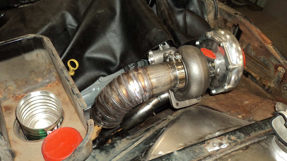
Crossover pipe done, waiting on 4″ downpipe to come in:
These links are here really for reference just so I can find them again in the future. And, considering shipping from China, arrived in 15 days:
3-to-4″ silicone elbow coupler
Also as a reference, but not (directly) from China:
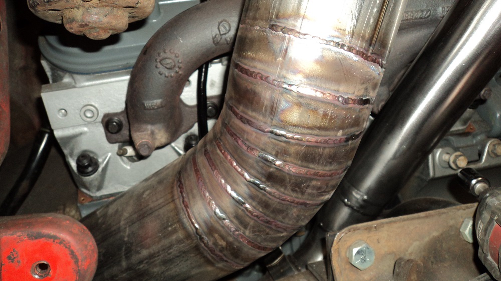
Still working out Argon flow, cup size, amperage, travel, etc.. I don’t have a lot of experience welding stainless. And then ran out of Argon. Again.
Gas lens, pyrex cup, 3/32″ tung, sharpened a little less pointy. I switched to 0.035″ filler as recommended by a fabricator buddy. It was easier to move quick with the thinner filler.
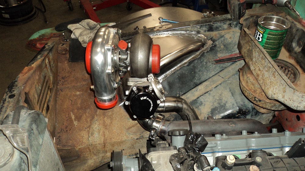
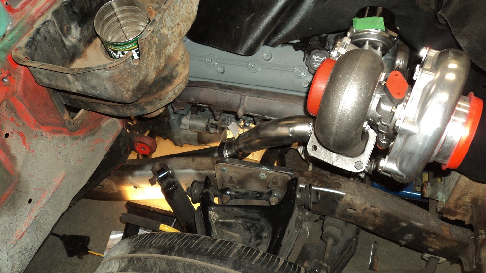
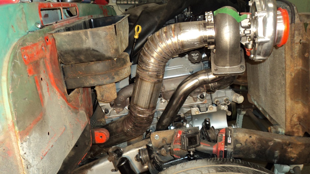
Running this pipe down was a lot less fun than it looks. I -can- actually get to the spark plugs. Needs another wiggle to get down to the frame, but it’s close.
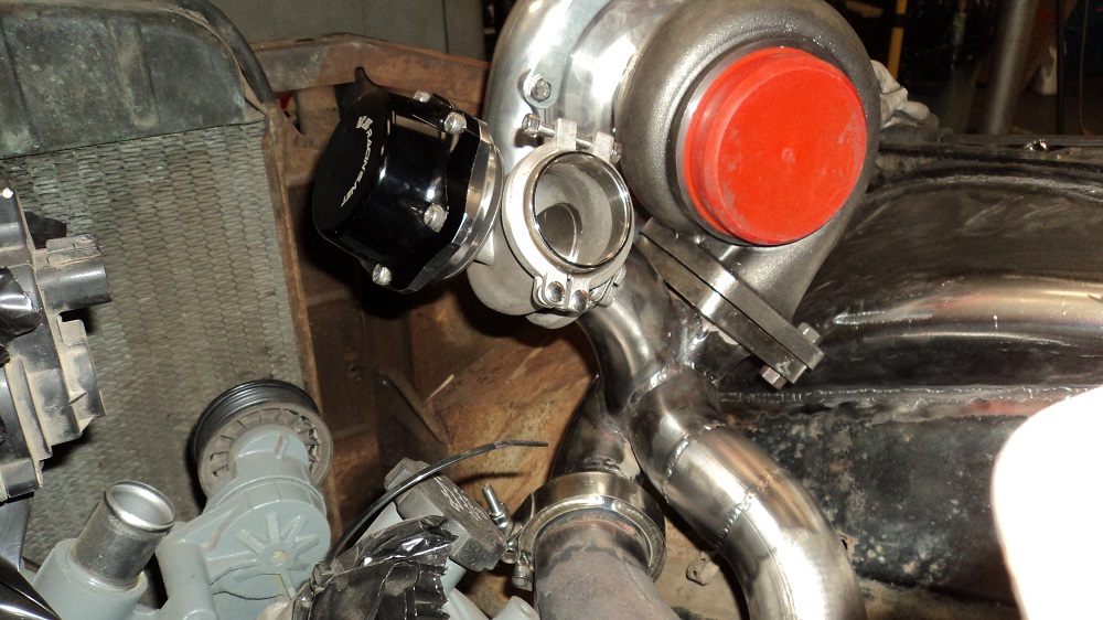
Wastegate plumbed. I TIG’d the merge into the downpipe, then TIG’d the elbow to the Wastegate flange, then cut a wee disc of 2.25″ to fill the gap, welding it all in place so that (theoretically) nothing warps or moves during the weld. I’ve let it cool completely in place, and will see how bad it is later.
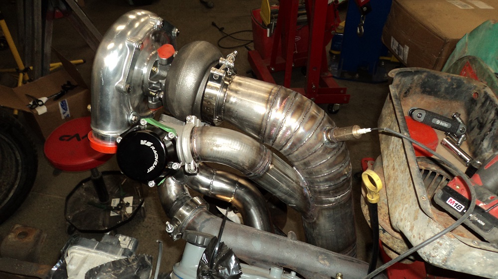
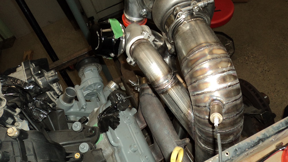
Working on the rest of the downpipe, intending to take it to a band clamp by the trans.
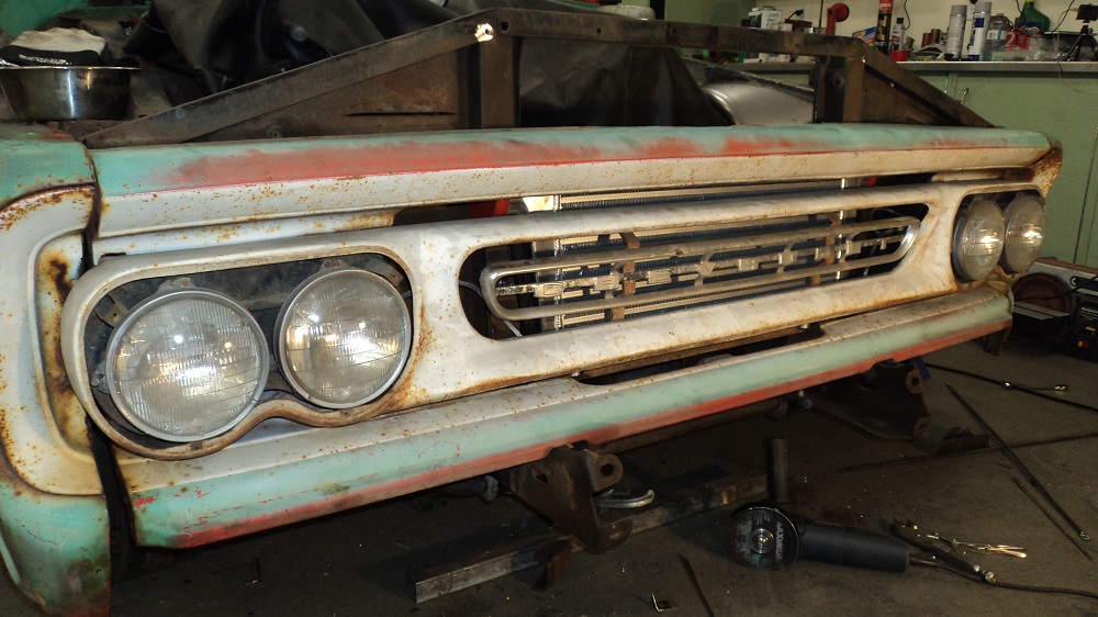
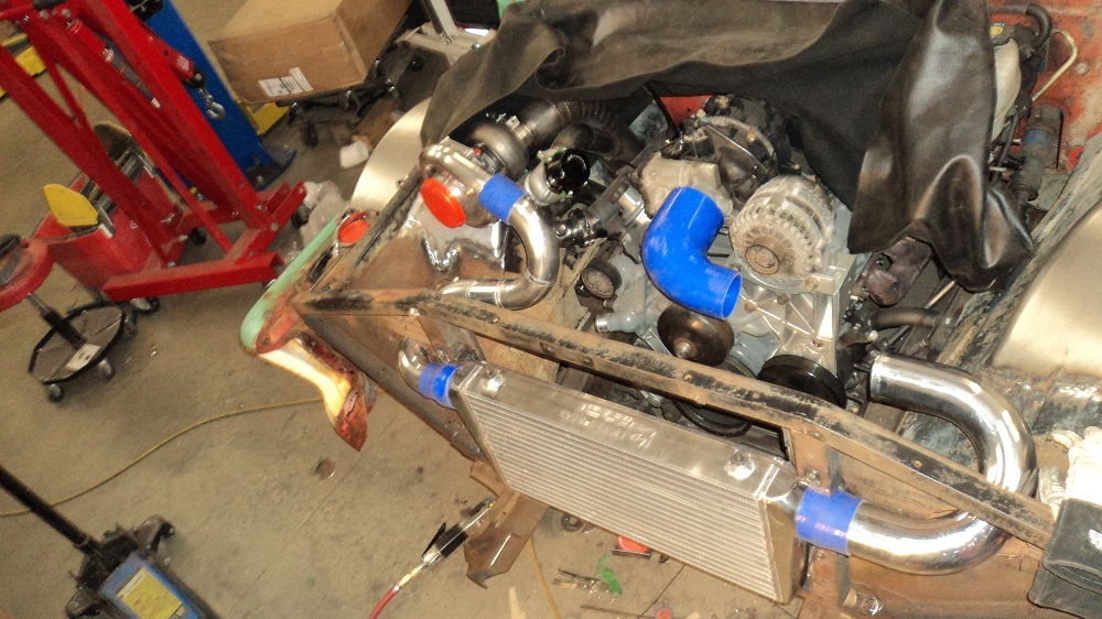
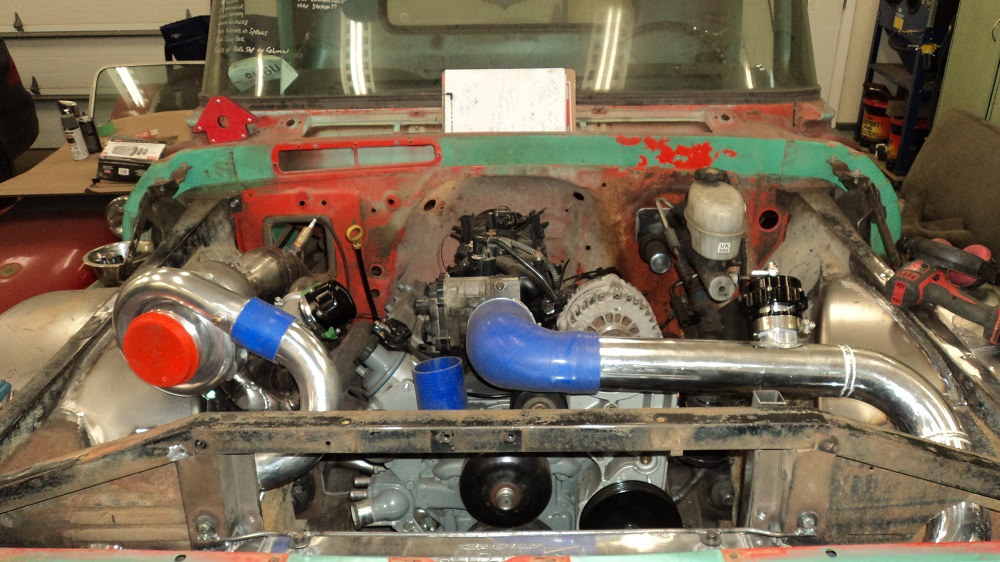
Trial fit of intercooler (VS Racing 31″ x 12″ x 3″). Required some cutting of the rad support, but it looks like the grill will fit fine with zero cutting to it. I will likely do a light skiff of black paint to hide it better.
Fabricating the cold side. I bought the wrong reducing elbow.
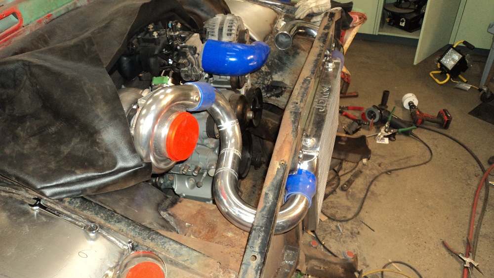
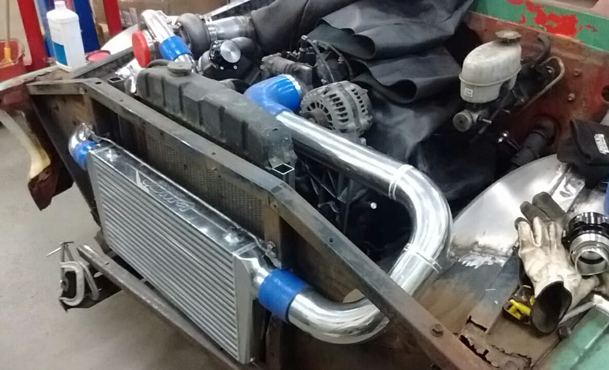
The only silicone coupler I could get in town was a 3″-to-3.5″, which I could NOT, for the life of me, get onto the LQ4 throttle body. I searched on eBay and bought a 3″-to-3-3/4″ 90° elbow, which should be here in a week or more. In the mean-time, I threw a hose clamp on the 3″-to-4″ 90° just to see if would even remotely tighten. Oh. Interesting. It does up and holds tight. Hmmm. Figures.
So, I piped the rest of the cold side, and since this picture was taken I welded the blow-off-valve mount in place. I have also spaced the rad out 1.25″ to theoretically fit an AC condenser between the rad and the intercooler.
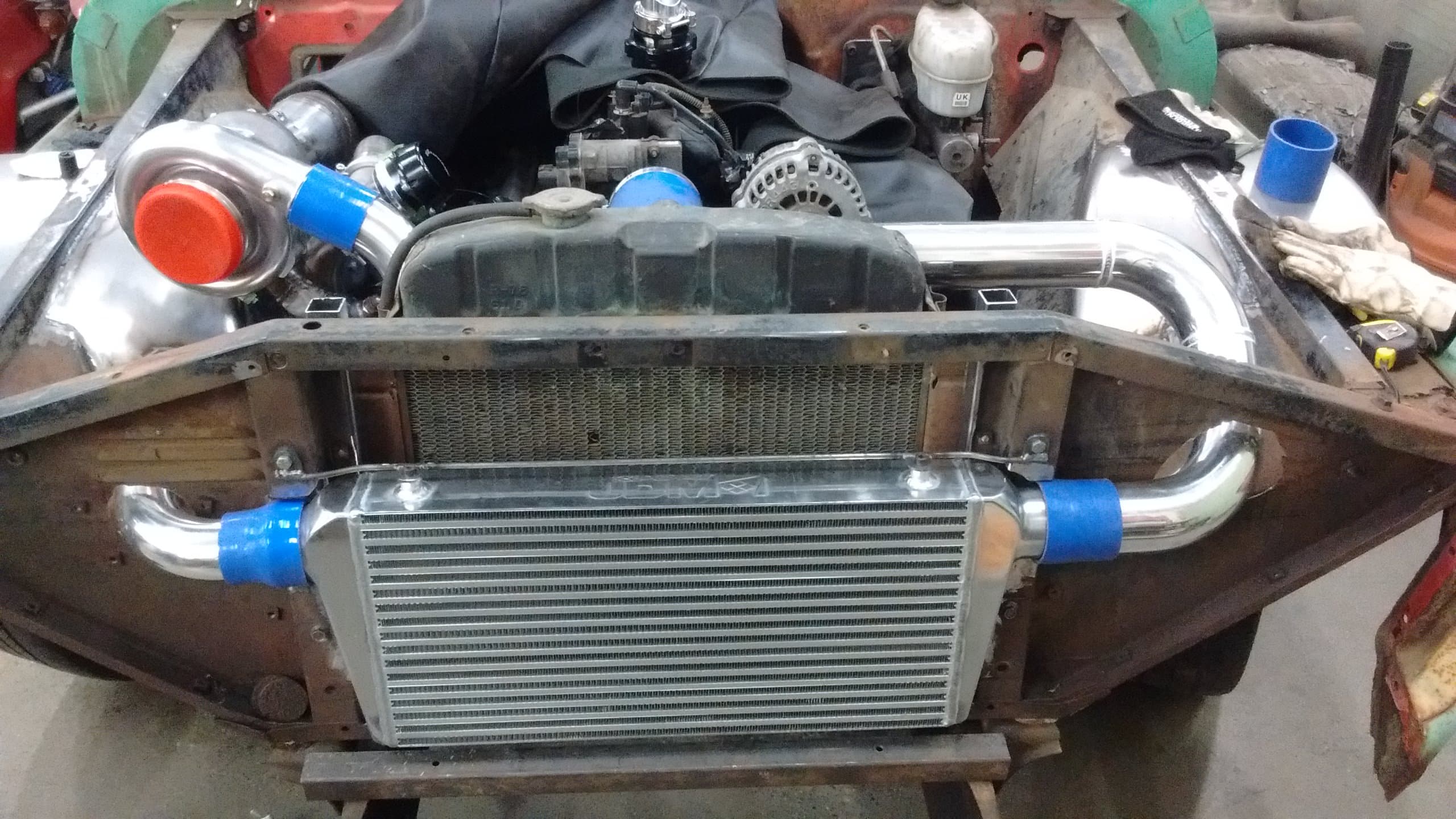
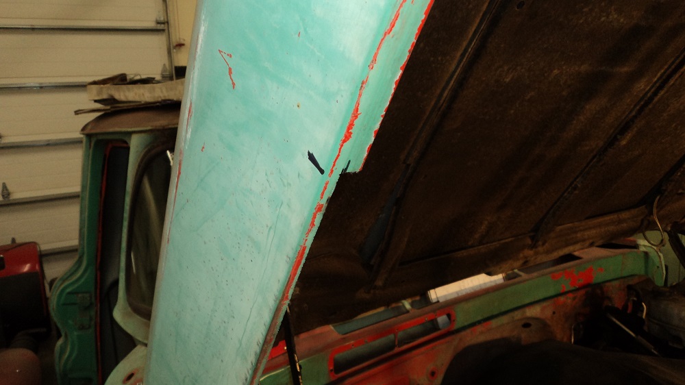
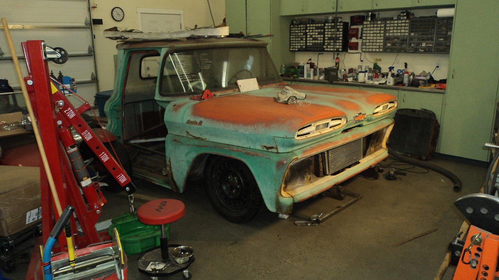
Now that the turbo plumbing is done (attached the blow-off valve, not shown), I really needed to know for myself if the hood will fit over the fenders.
First I had to re-shape the hood hinges. No room for springs, so the spring “ear” was cut off and re-flanged for strength. Then placed in the engine bay and clearanced for the fenders and flanged.
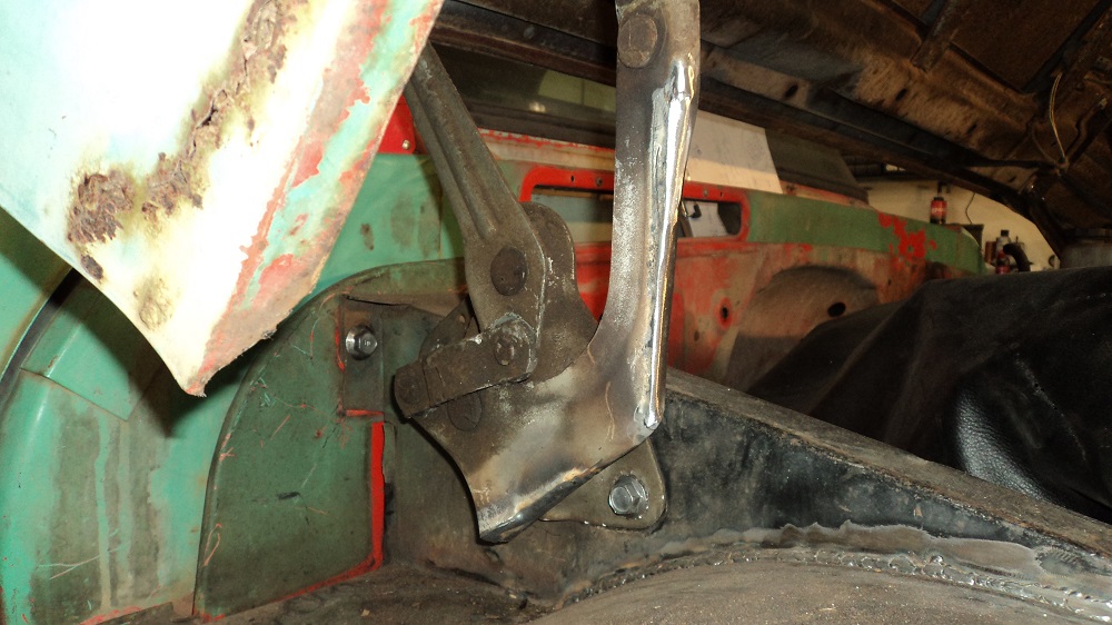
The hood had about 5/8-3/4″ trimmed off the inside edges around the wheel humps, and it fits!
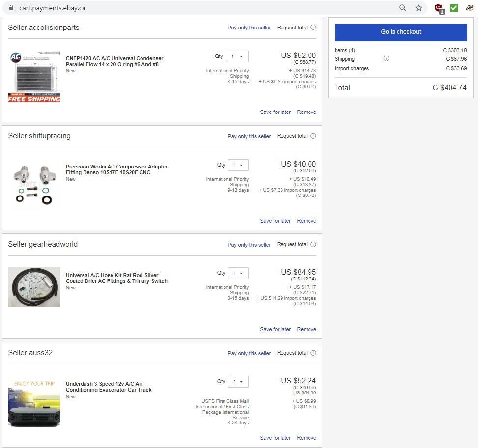
Also ordered my A/C components, because I need to figure out the fitment of the condenser and whatnot.
Somebody posted their order on one of my FB 60-66 groups, and wow – that’s cheap (and yeah – you’re looking at Canadian dollars for my order)!
Oh – BOV mounted.
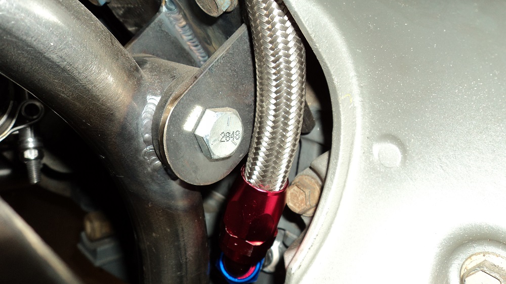
Oh, and here’s the first of the “I clearly didn’t plan this thoroughly enough:” the oil return I put in the pan is right where the motor mount ended up, which was too close to fit any of the AN fittings I have; they all hit the motor mount one way or another:
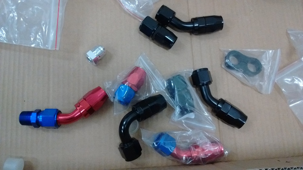
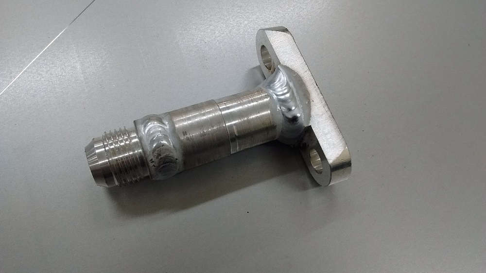
So I bought bought a 90° elbow, which didn’t fit because now the flared end hit the motor.
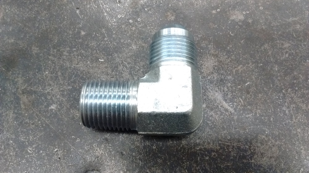
So I hacksawed it in half, cut it down, and re-welded it as a 45°. I’m sure you can buy these, but this was easy.
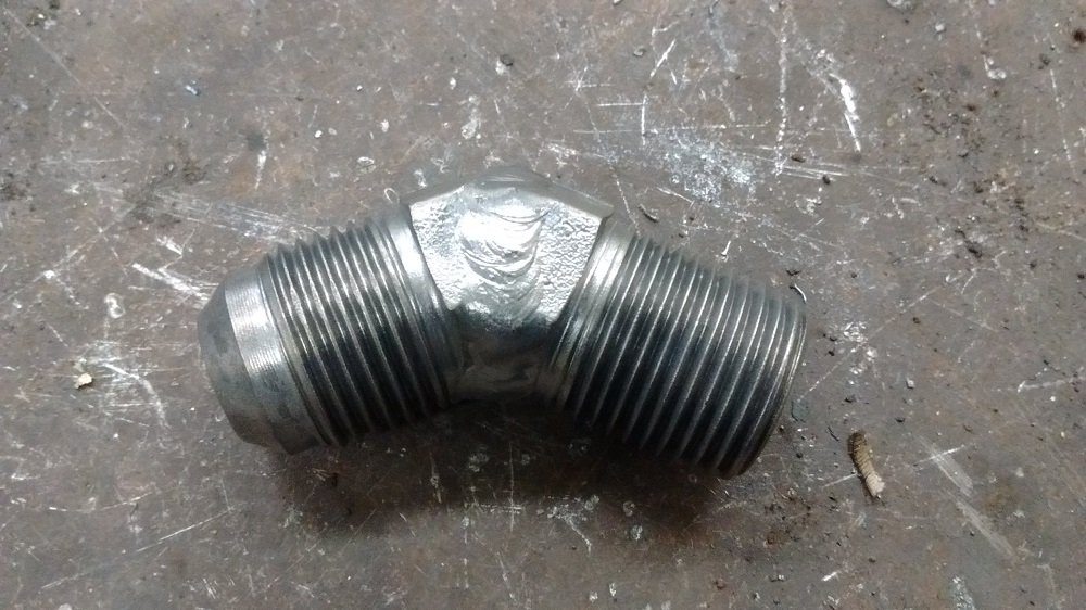
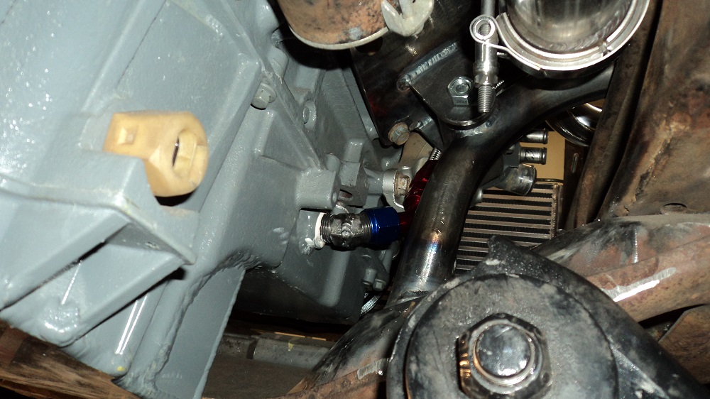
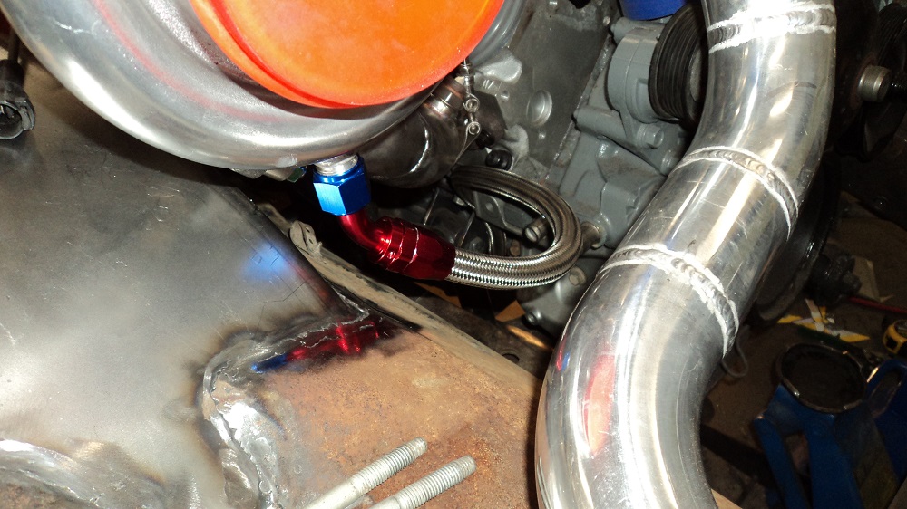
Then I used a 45° AN fitting to get the hose to it. Looks like it will clear the AC compressor, and I’ll likely put some rubber hose around the braiding so it doesn’t machine its way through things.
Except it looks like I clocked the turbo compressor and turbine in such a way that the supplied oil drain AN fitting (angled slightly to clear easily) won’t fit. Figures. So I lengthened it two inches, and (what the heck!) ported the adapter for nice flow.
Other than running the turbo oil feed (I need a 90° elbow so the hose won’t kink/hit the hood), this concludes plumbing the turbo.