[ Start ] [ Index ] [ Parts List ]
In Which I Rebuild the 4L80E
This was actually performed just prior to putting the primered cab on the painted chassis.
Fully Rollerized, plus mods.
Articles from Gears Magazine :
Correcting Carrier Float in a 400 or 4L80 Transmission
Improve your 400 and 4L80 Rebuilds
Threads referenced for the build:
Bob Is The Oil Guy: 4L80E Rebuild Questions That Have Not Been Answered
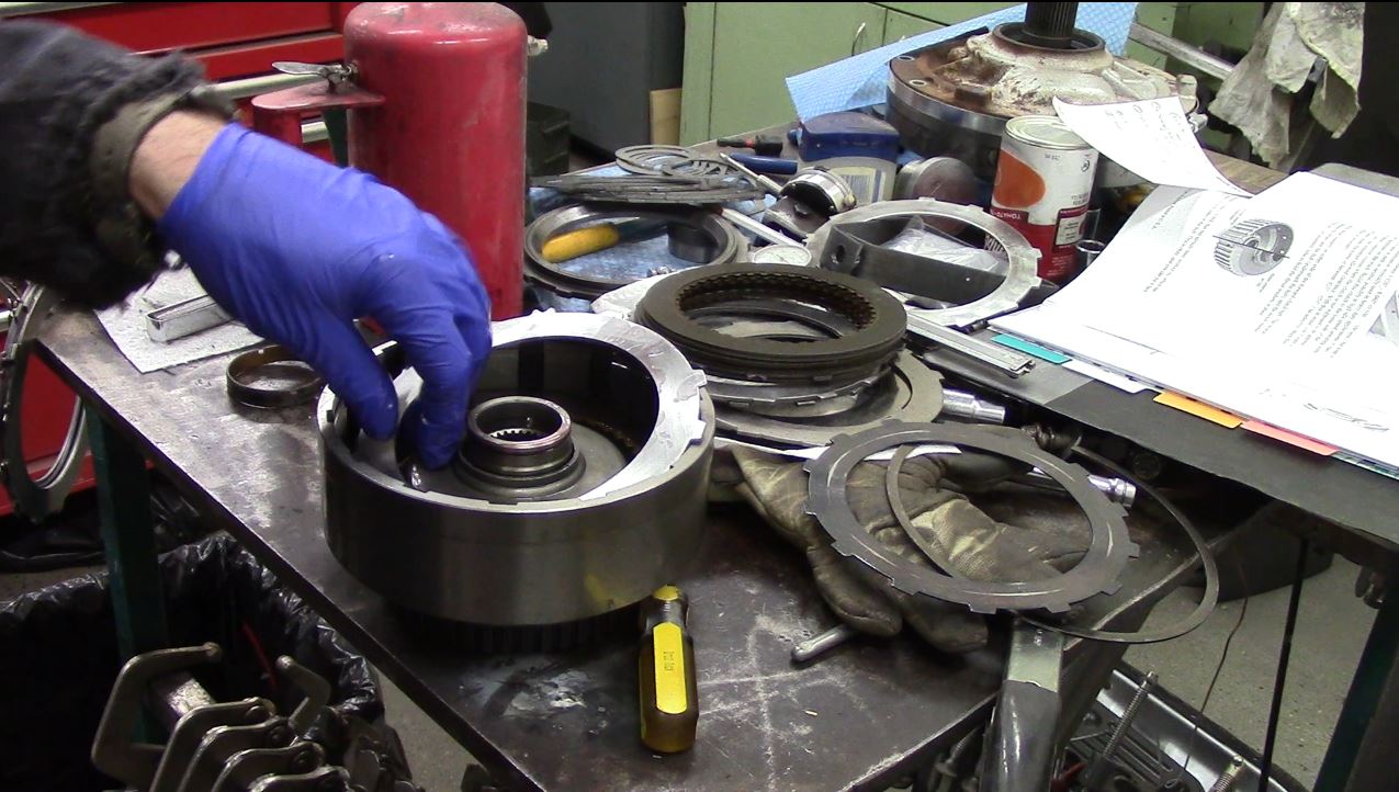
Transmission was completely disassembled, all bushings inspected, and all clutch clearances checked. Trans is M-I-N-T.
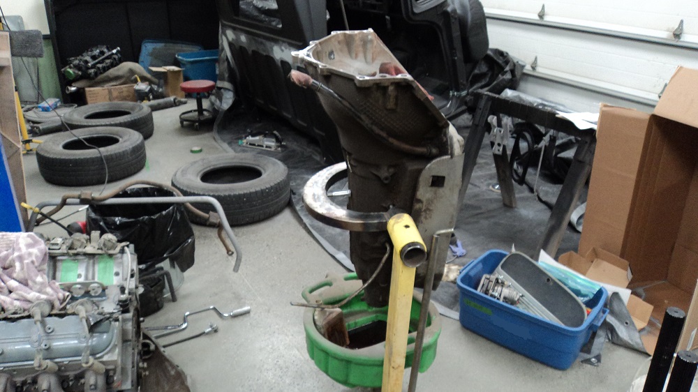
There is a wealth of information online for doing this. This trans will also be beefed up a bit.
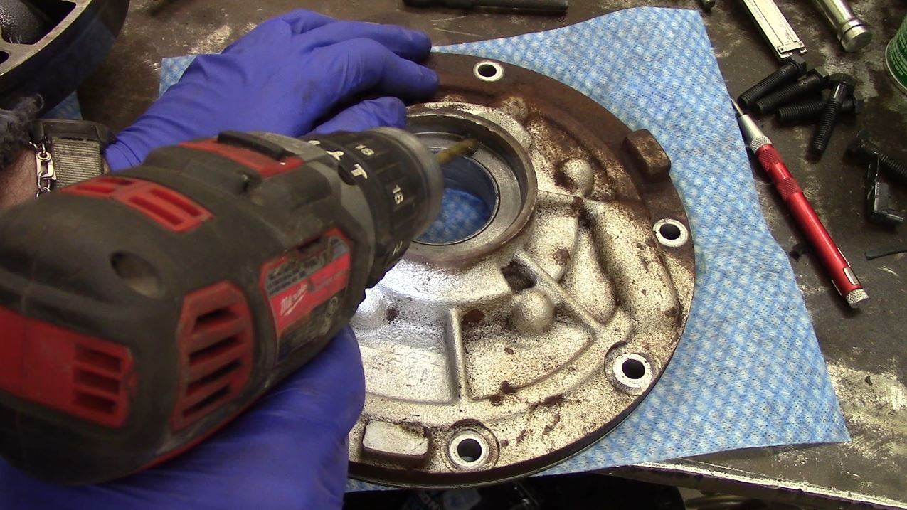
MOD 1: Rollerized Output
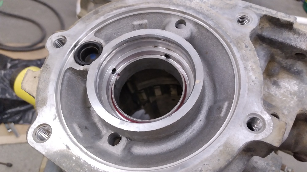
I used a Late 4L80E pump bushing (0.700″ wide), protruding 0.100″ into the case, with 0.125″ protruding out back, assisted by red loctite and staked in place. Other people use an Early 4L80E pump bushing (0.550″ wide), or a TH400 case bushing (0.615″ wide), or a Sonnax “No-Walk” bushing (0.690″ wide) installed backwards. The original case bushing is 0.419″ wide, and rests in a 0.475″ wide bore.
A TH350 pump bushing (AC Delco 9436851) is placed inside, black side against the case, with about 0.020″ shims underneath.
This mod helps deal with huge amounts of rearward thrust that the 4L80E sends to the back of the case.
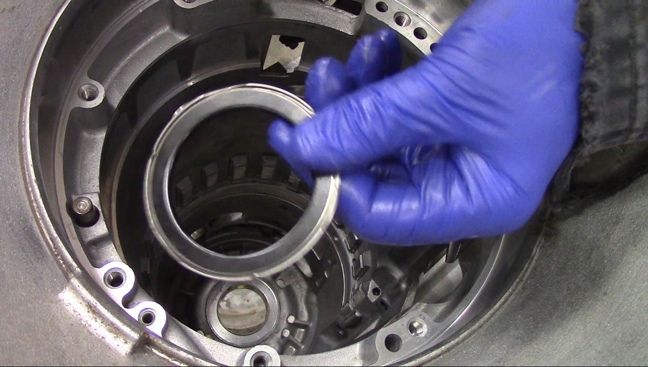
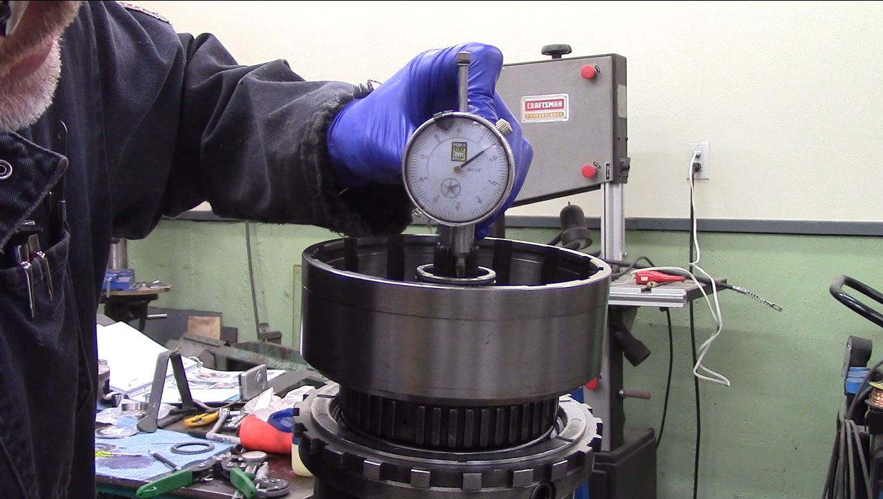
This setup needed a 0.025″ shim to get the end play within 0.003-0.008″ rollerized end-play. Bearing-Cam (black side DOWN):
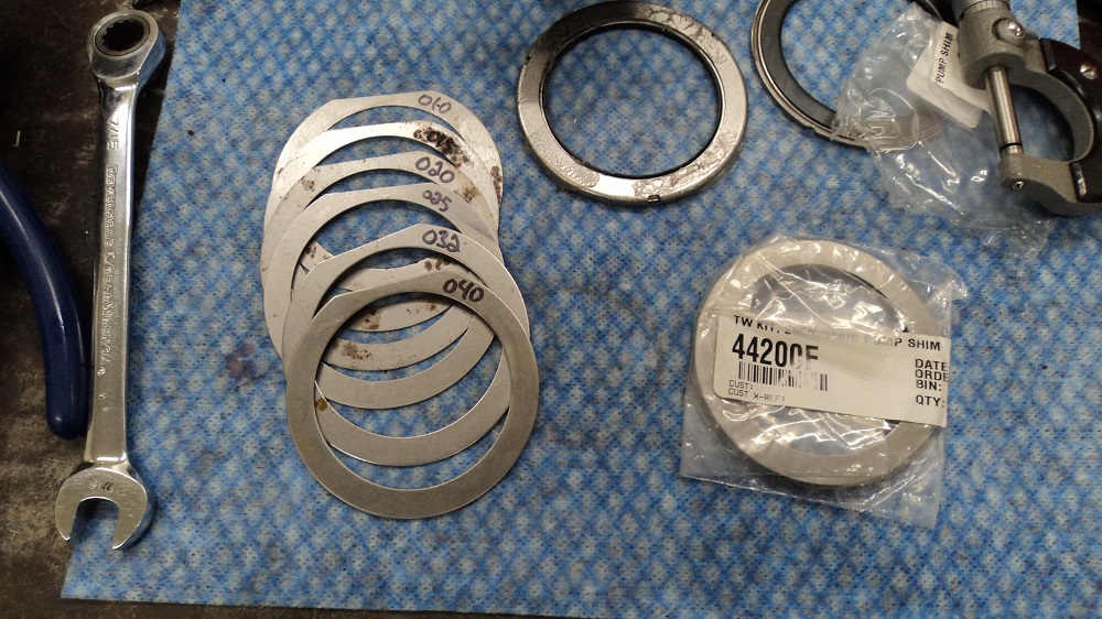
Shim Kit:
MOD 2: Rollerized Reaction Carrier
This tightens up the reaction carrier (it “floats” and is pretty sloppy), and deals with the forces at the reaction carrier. The factory put a plastic thrust washer there. This should reduce friction, but also plays a role in reducing end play and making the reaction carrier more stable.
The reaction carrier gets machined to fit a TH350 pump bearing (2.875″ OD, 0.075″ deep):
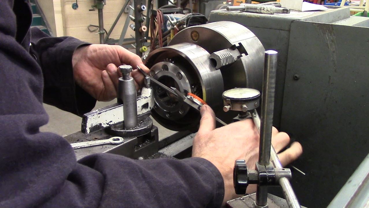
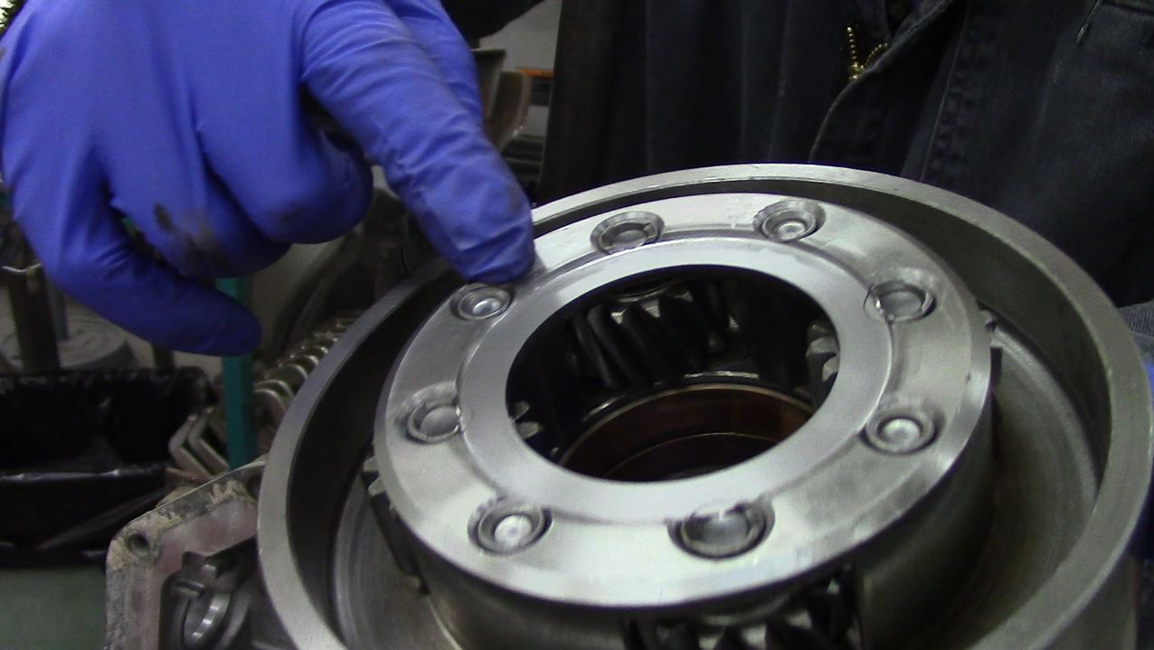
The pump bearing needed to be clearanced to slip over the sun gear.
This setup needed zero shims to get the end play within 0.002-0.006″ with the center support.
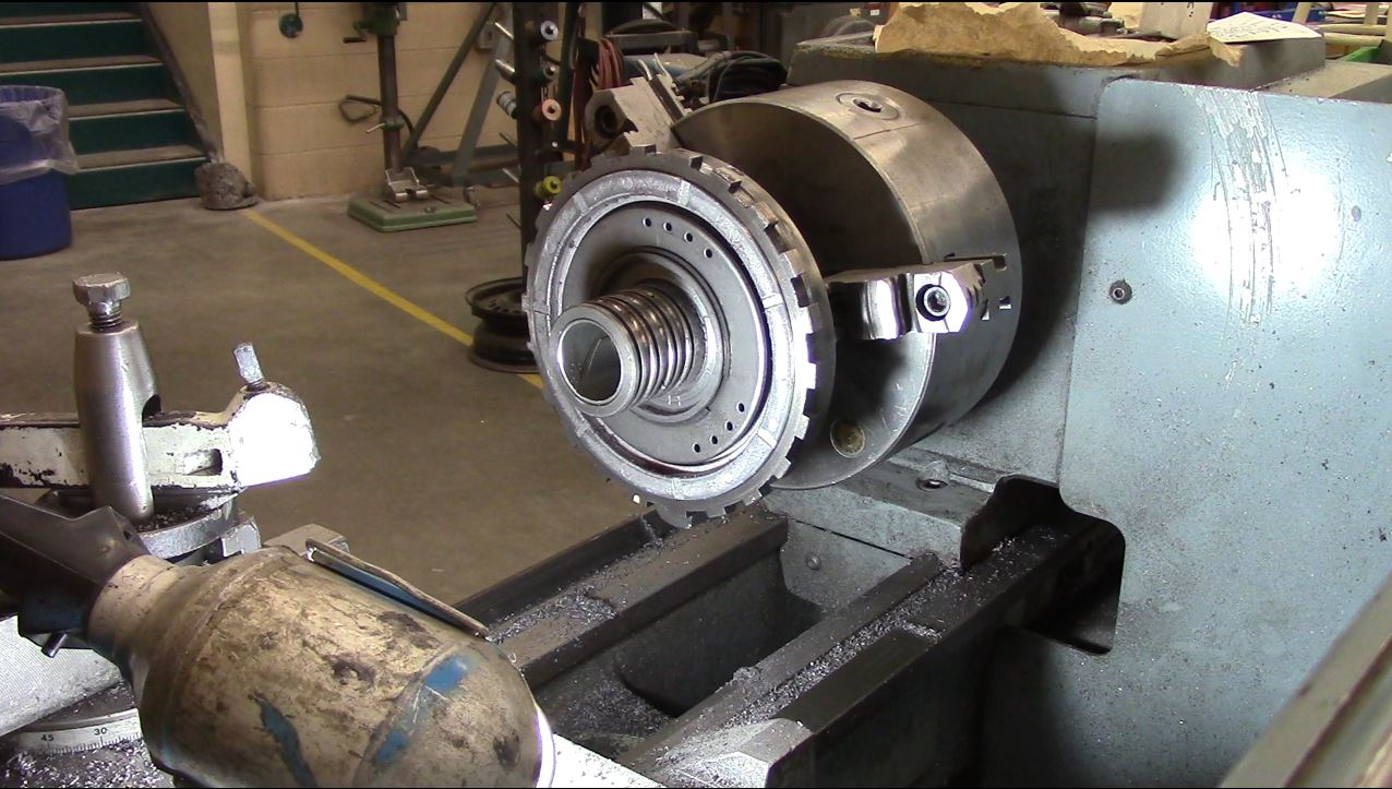
MOD 3: Rollerized Direct Drum
This takes the forces that come through the Direct Drum, and STOPS them at the Center Support. As designed, the forces are applied direction to the Sun Gear Shaft and into the back of the case.
The center support gets machined to fit a TH350 pump bearing (2.875″ OD, 2.125″ ID, 0.375″ deep):
MOD 4: Dual-Feed Direct Clutch (Part 1)
GM likes to have a Direct apply piston that is kinda split in half. It’s like two concentric circles. One half is used to apply Direct, and the other is used to apply Reverse. By altering the fluid flow in the trans, you can make Direct and Reverse use the entire piston. It does end up applying a bit slower (and more forcibly in Reverse, but you will be ok).
Eagle-eyed viewers will notice the second sealing ring from the top has been removed. This is part of the Dual-Feeding modification. Roughly triples the application force of the Direct clutch.
With respect to the Direct Drum Rollerization, this setup needed 0.035″ shim to get the drum 0.005-0.010″ off the bottom:
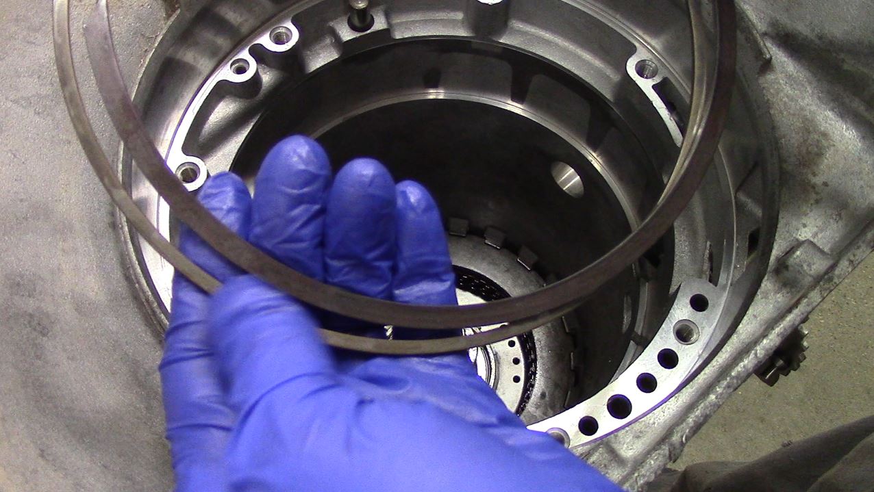
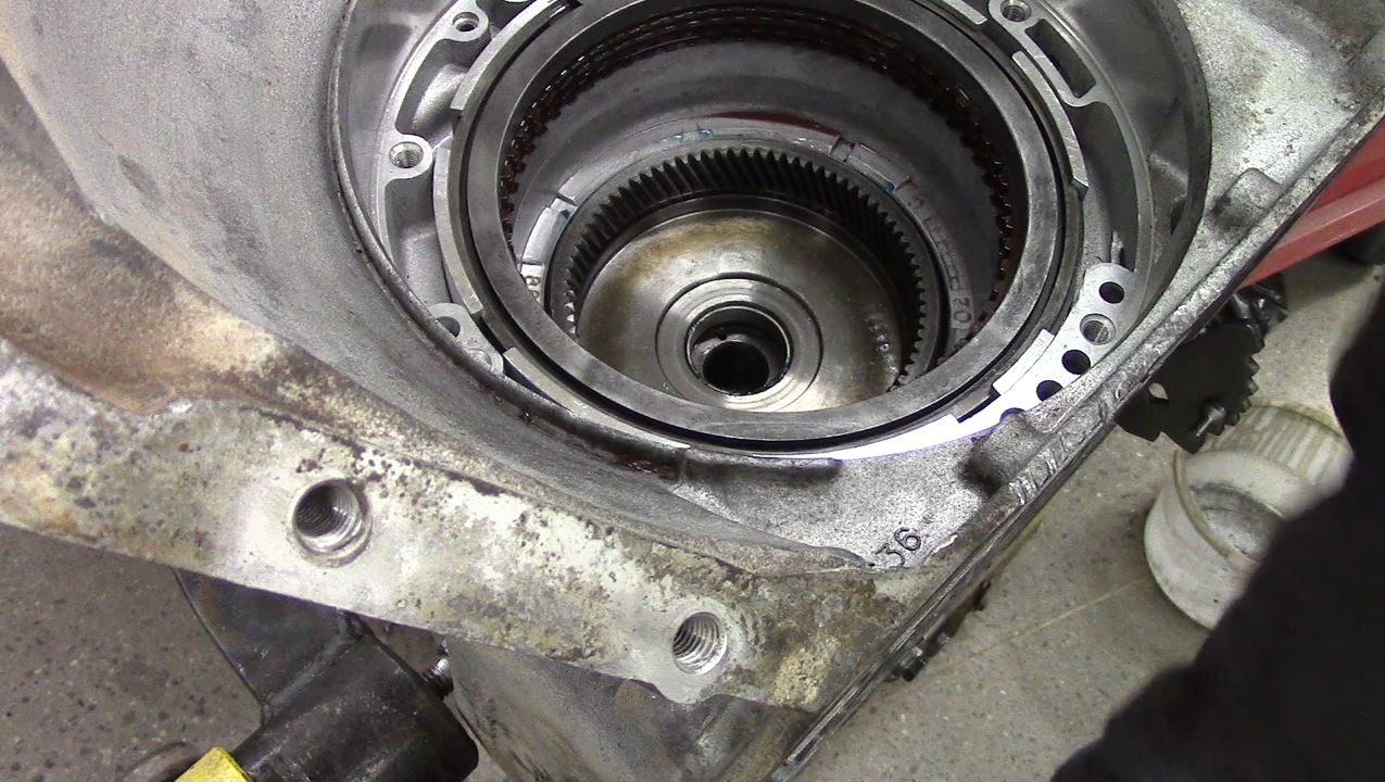
Everything got installed into the case. Save yourself hours of arguing with the Center Support Snap Ring, and notice that one edge is chamfered. You can thank me later:
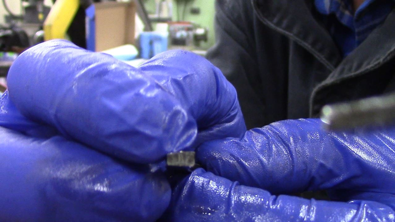
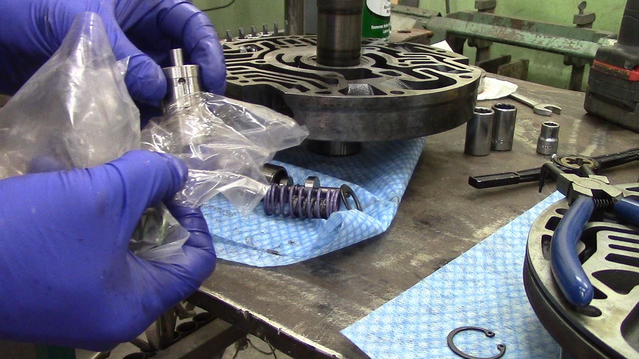
MOD 5: Heavy Duty Intermediate Snap Ring
The factory ones break too easily.
Some say it’s from a 727 Torqueflight, mine came in the TransGo kit. You can see the physical difference:
That’s as far as I can go until my TH400 direct piston comes in….
With a little Silicon-Bronze TIG action:
MOD 6: Dual-Feed Direct Clutch (Part 2)
I removed the center lip seal in the drum, which is part of dual-feeding the Direct apply piston. This removes the separation between the Direct and Reverse sections of the apply piston.
MOD 7: 6-Clutch Direct
Lots of internet opinion between running a TH400 direct piston, vs just keeping the 4L80E bonded piston. I kept the bonded piston, tossed the wave plate, and squeezed in six frictions by using six 0.077″ forward steels. Clearance ended up a perfect 0.060″ (0.010″ per clutch).
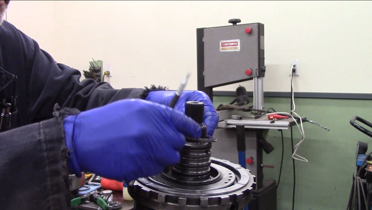
MOD 8: Rollerized Forward Hub
The Direct Drum is pretty sloppily supported. We are going to reduce the slop, and add a Torrington to better support the Drum.
Following Interweb advice….
To do this, the Forward Hub “shoulder” gets machined to fit Ford AOD Torrington bearing (I used 1F1Z-7F404-AA). The “shoulder” is machined down: (bearing thickness) minus (original thrust bushing thickness) minus (about 0.030″ clearance reduction), which in my case should have been 0.050″, which I thought I initially cut. I may not have.

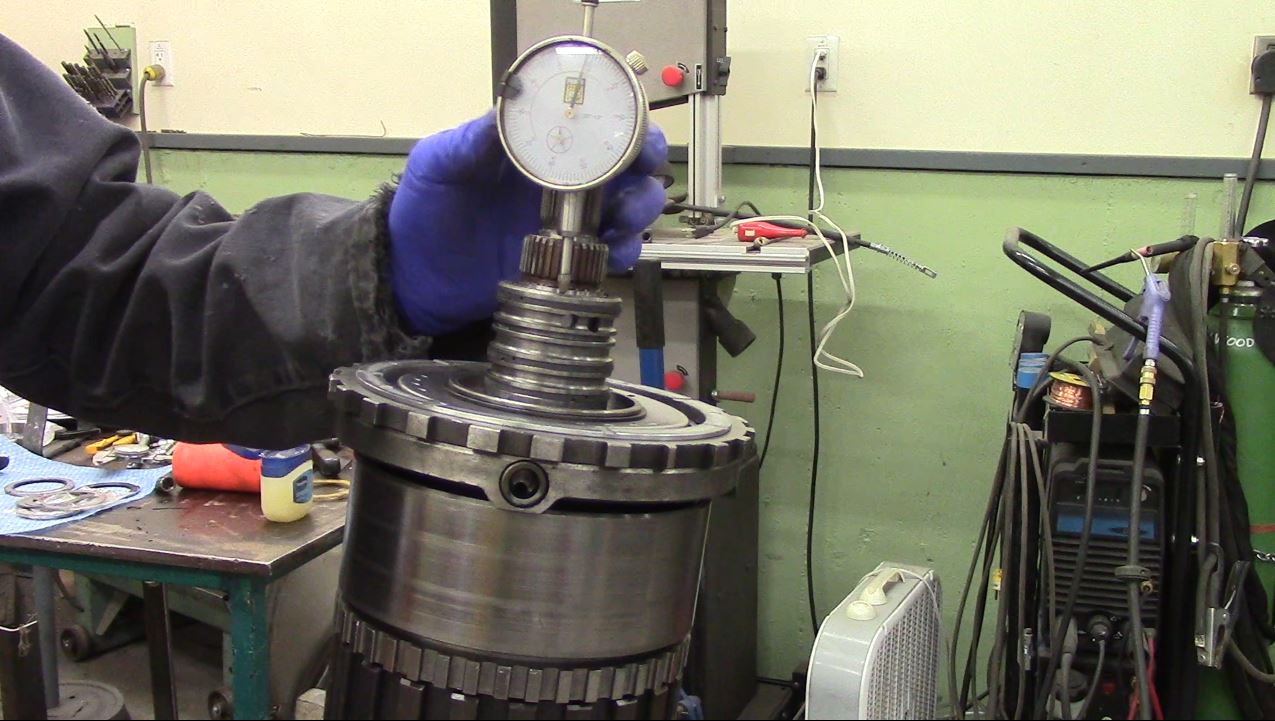
Now, you also need to know that Direct Drum to Forward Hub clearance should be 0.003-0.008″ when rollerized. I’m not exactly sure how to measure this, you can’t exactly get a dial indicator in there. Machining the shoulder more, should move the Forward Hub closer to the Direct Drum. With what I had initially cut, there was a noticeable amount of drum-to-hub play. I also ended up with ZERO front end play in the trans.
I don’t know if this is correct, but I measured the distance from the Direct Hub to the mainshaft, and got 1.911″
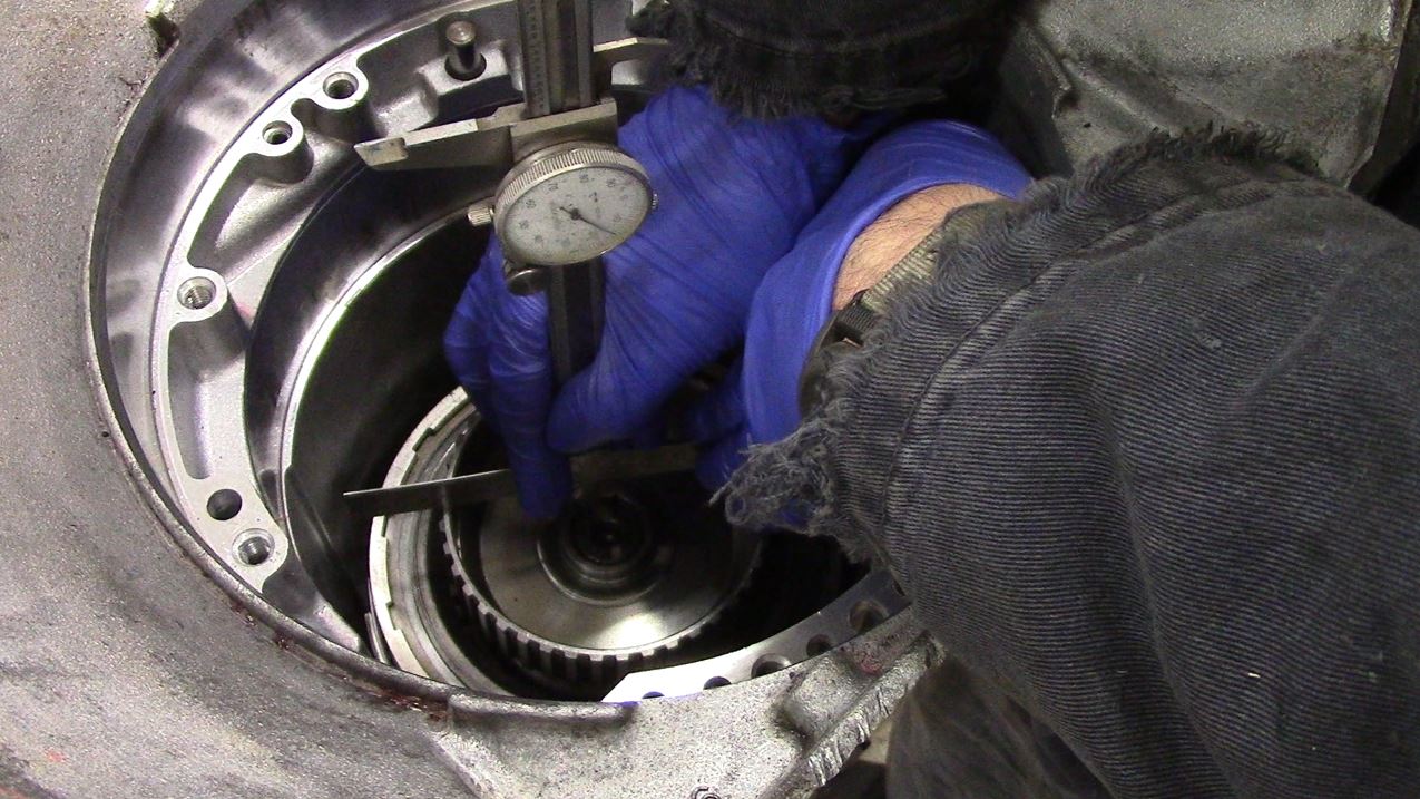
I installed the forward bearing (0.143″ thick) and got 1.933″
Again: I don’t know what I’m doing.
The difference was 0.022″, and in my head it made sense to cut 0.017″ more off the Forward Hub (0.005″ clearance), which makes NO sense to me right now. But this gave me 0.010″ front end play in the trans, which is bang on what I wanted (.005″ more than the rear). I hope this works.
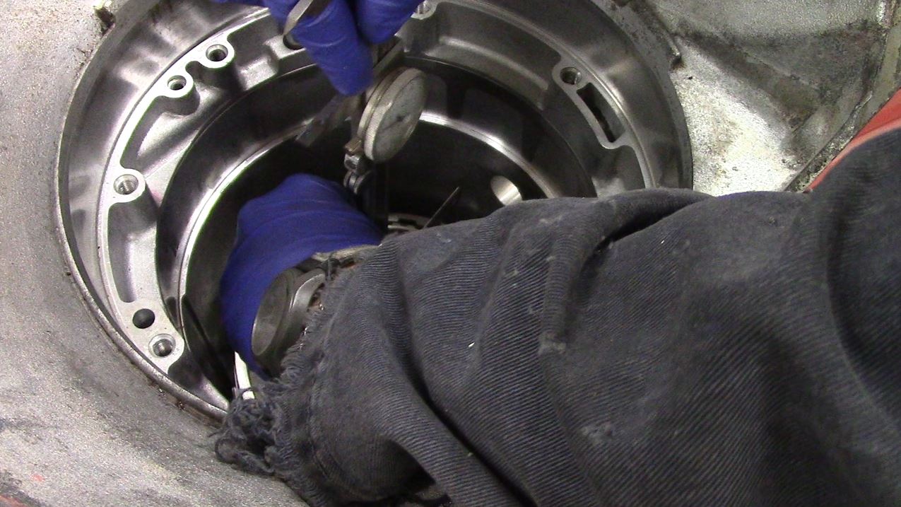
NOTE: The 0.050″ cut will get you in the ball park. You really need to assemble the trans and check the Front End play, and machine the shoulder to get the end play where you want it.
Front end play should be 0.002-0.005″ GREATER than the rear end play (if you are NOT lifting the output shaft to take up rear end play).
4th clutch installed:
Overdrive installed:
MOD 9: Overdrive Lube Feed
Overdrive lube hole drilled out to 1/8″:
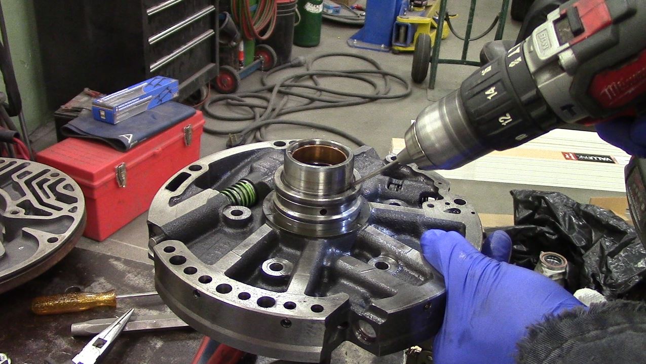
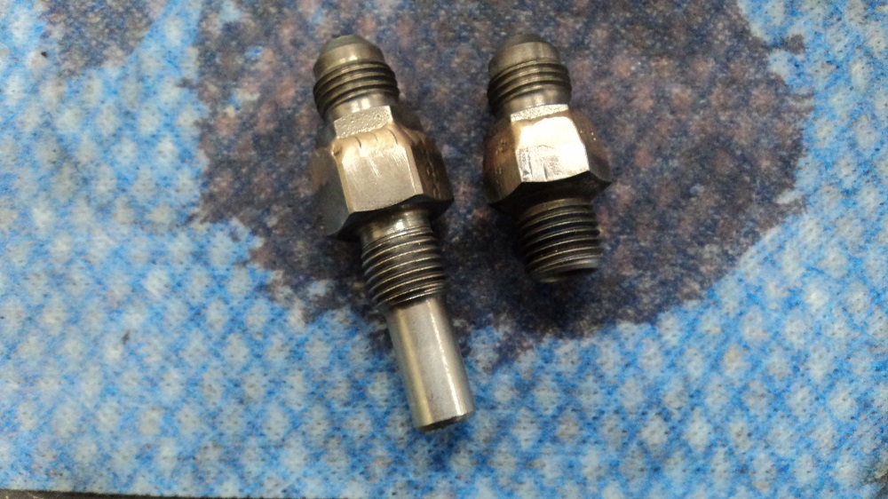
MOD 10: Converter Charge Line
Drilling a 0.050″ hole provides the converter with charge oil regardless of pressure regulator. This will increase pressure in the converter, and more oil drain back.
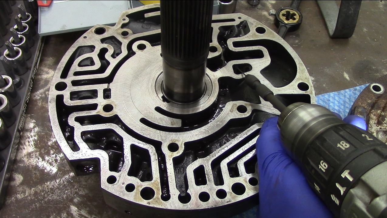
MOD 11: Converter Oil Drainback
The existing drain might not be large enough for the increased oil, so we’ll drill it out to 1/4″.
MOD 12: Pressure Regulator & Boost Valve
This is just remove and replace. I used the one in my TransGo kit. Allegedly Sonnax is more desirable, but my interweb research suggests it really doesn’t matter which one you use. This was annoying to install.
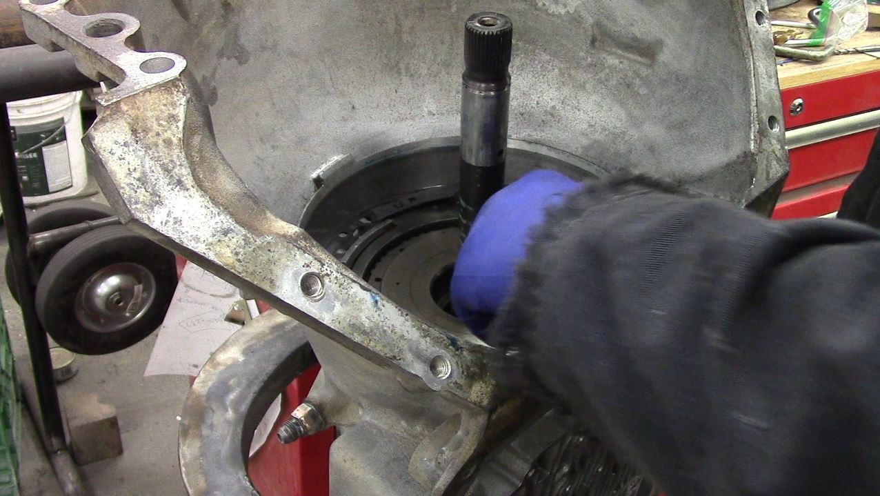
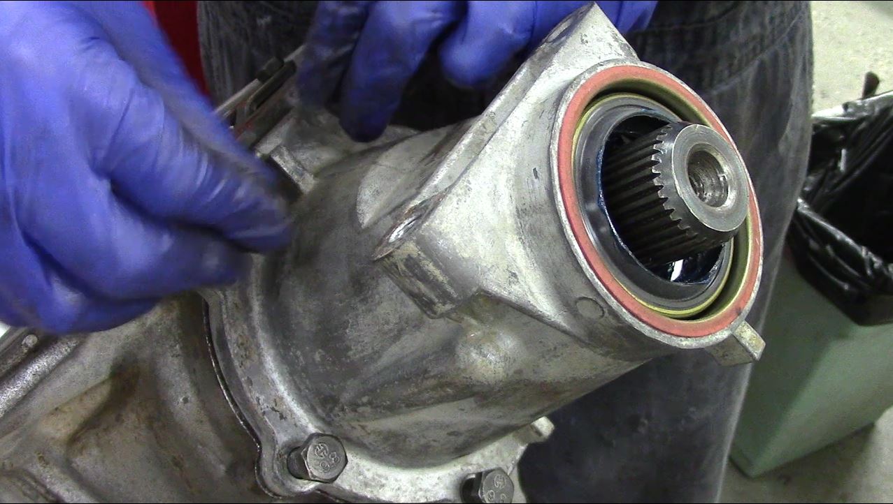
Pump installed:
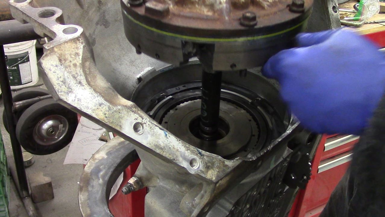
Rear seal inserted ONLY enough to allow the snap ring to snap into place (makes sure oil gets to rear case bushing).
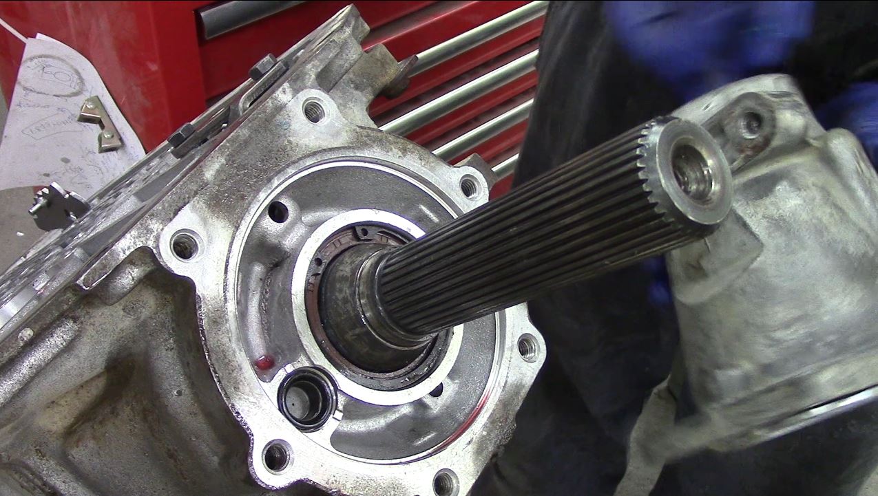
Extension Housing installed.
Now things become smoke and mirrors:
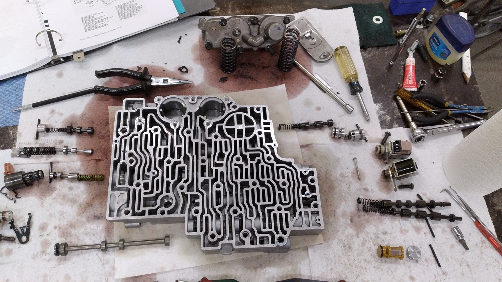
The very likely worn AFL valve and bore was reamed and re-valved with a TransGo kit (48-ACT-TL), and the TCC valve was replaced just in case with a Sonnax unit (34994-01K). They are problem areas. I’m here. They’re cheap.
I installed the Sonnax Over-Run Clutch Valve kit (34200-40K), which keeps the over-run clutch applied in all gears except 4th, adding strength to the wee over-run sprag. Not needed if you always remember to shift into 3rd before doing stupid things, but I’m getting old and forgetful. Or someone else might drive it and not know. This involves some drilling of the valvebody, and some plugging of holes in the separator plate.
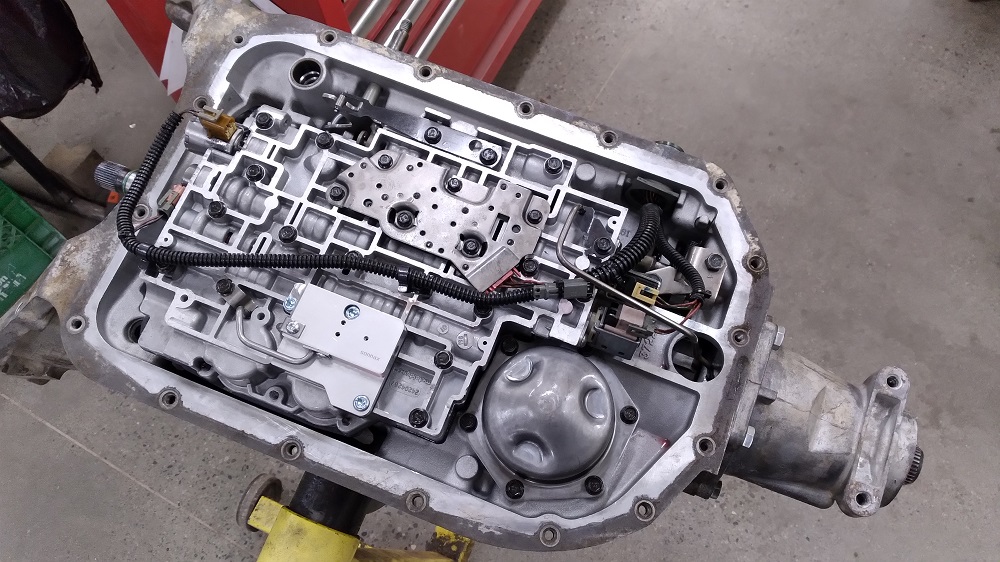
From the TransGo shift kit (4l80E-HD2):
I used both springs in the the Accumulator Control Valve, and used their 0-ring’d cap.
I installed the Actuator Filter tapered/o-ringed plug, new spring, and new plug. This required some trimming of end of the filter to fit as per instructions.
I drilled 2nd apply hole to .0935″ (#42), and 3rd and 4th were both drilled 0.0995″ (#39).
I installed the 3rd Accumulator spring (I debated deleting the accumulator altogether, but based on my research, and the fact that I’m running the stock converter and no wave plate in 3rd, I felt it was wiser to keep it).
I removed the Reverse check ball (ball #9), but did debate drilling the Reverse apply to 0.0935″ and leaving the check ball in. Some say leaving out the check ball makes for a harsh Reverse apply. If this sentence is still here, I have not gone back and changed it (update: It’s perfect).
I left out the 1-2 servo sleeve. Jake Shoe prefers to leave this out, as it may cause some drag. I’m not convinced I have anything to gain my including it.
I did NOT perform the pressure relief valve mods.
I also replaced solenoid o-rings.
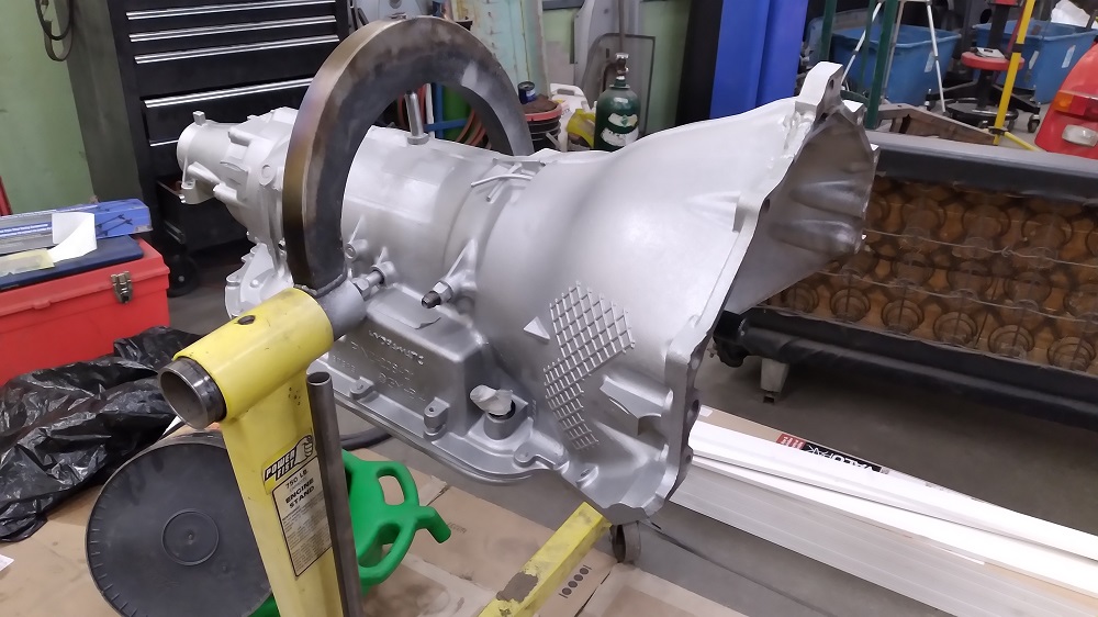
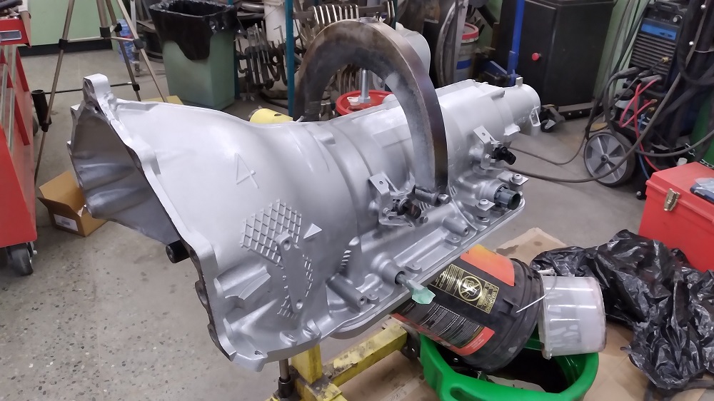
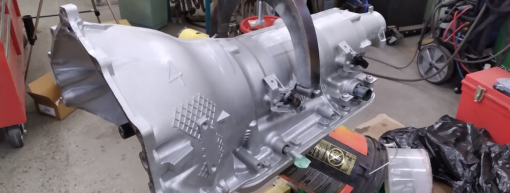
Picked up a filter, attached the pan, and a spray of Aluminum engine paint.