[ Start ] [ Index ] [ Parts List ]
In Which I Build Motor Mounts and Inner Fenders
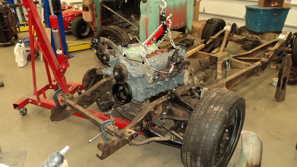
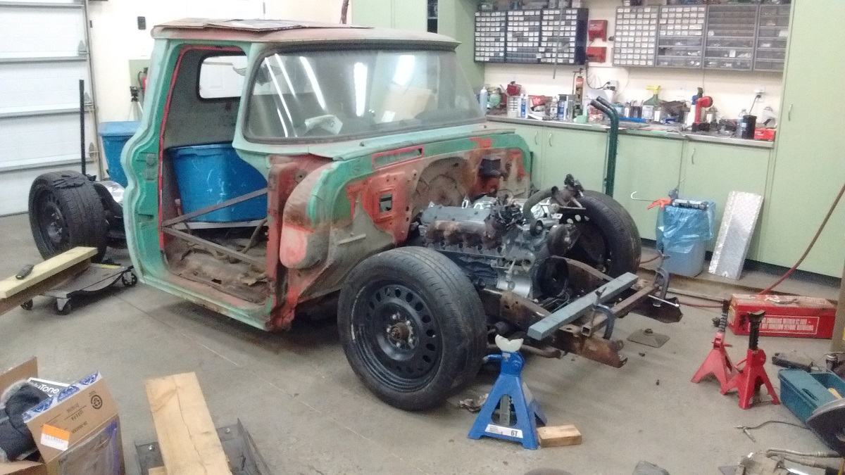
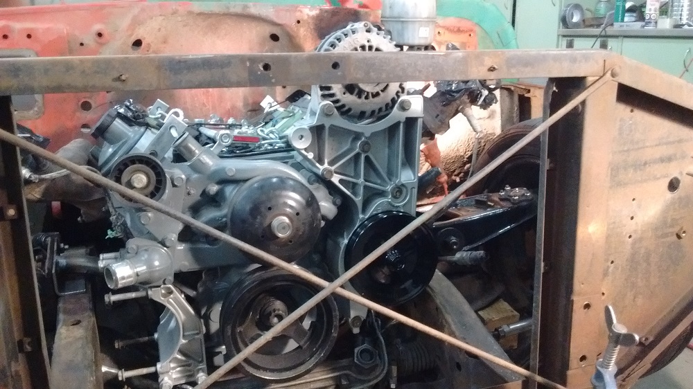
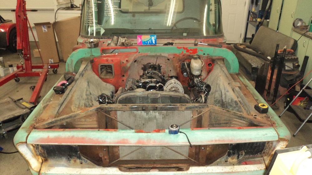
Trial fit the engine and trans into the frame. Yes, I will have to shorten the oil pan about 1.5″, or spend $200+ for a F-Body pan, assuming I can’t find one at the wreckers.
Shortening the Oil Pan
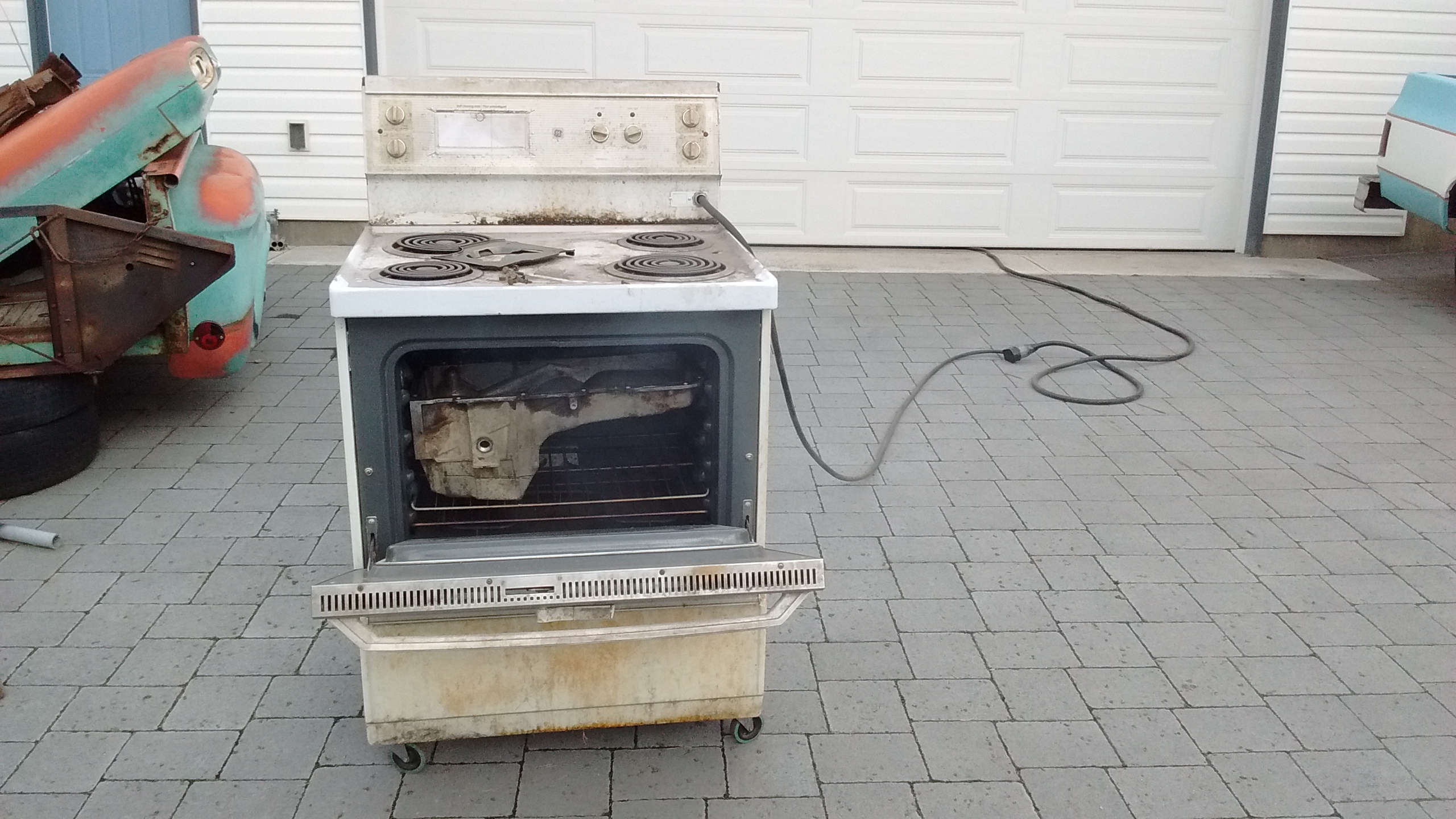
Baked all the oil off in the oven for seven hours. Cooked it outside because I don’t fully trust my electrically-molested oven inside the shop.
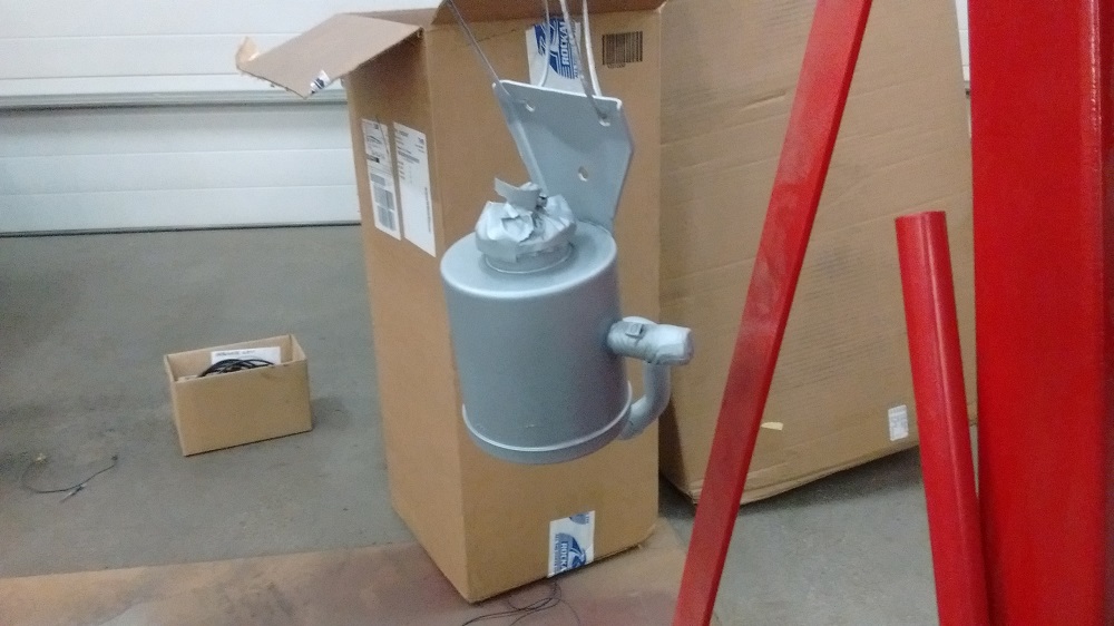
Pieced together the bottom of the pan using 3/16″ Aluminum plate. I’d already be finished, but I ran out of Argon. The pan is not as short as the F-Body LS pan, but I lengthened it to match. No idea what the capacity is now. The bottom matches the bottom of the 4L80E.
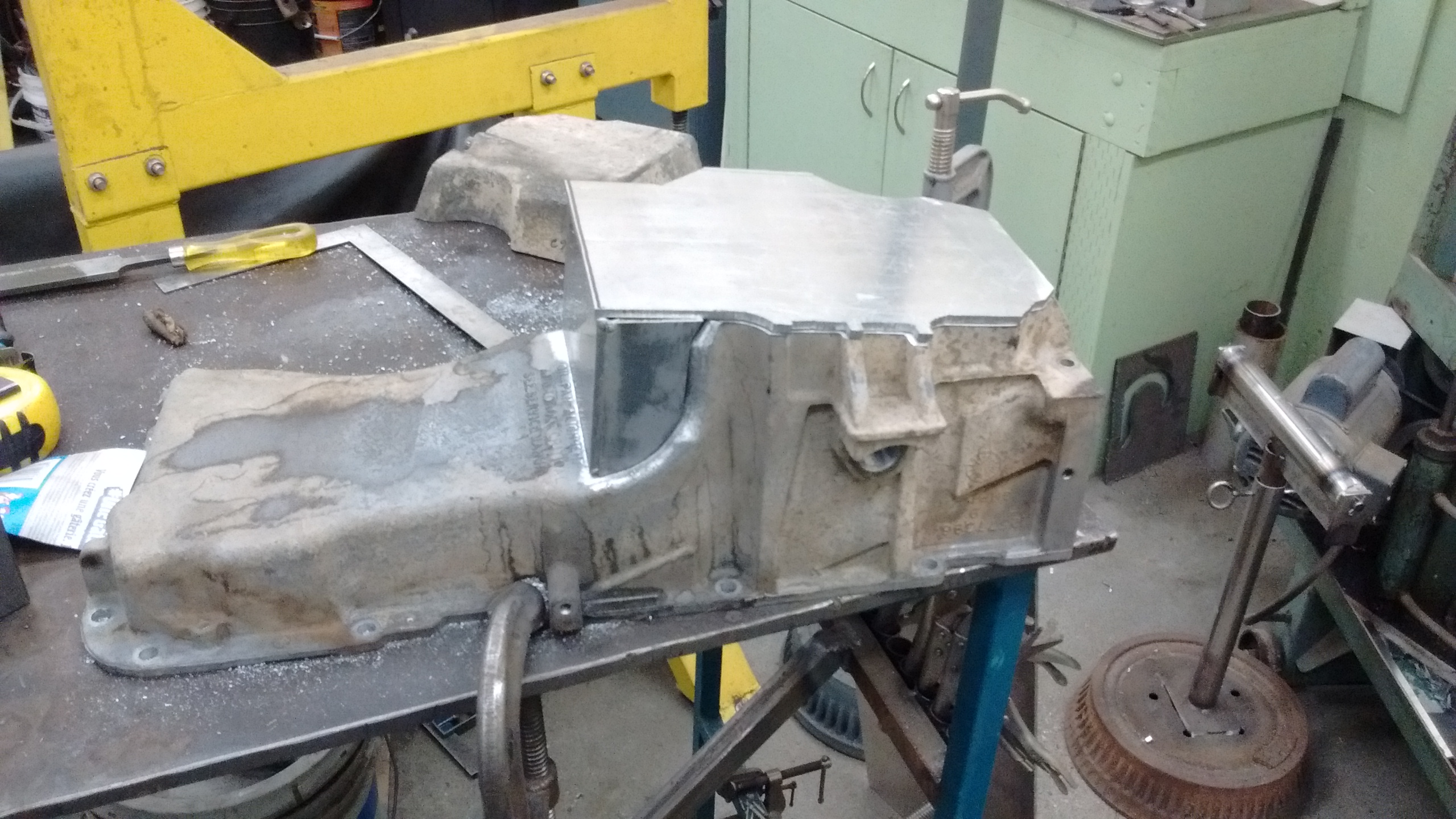
Pan welded up. It was not fun aluminum to weld. I also sharpened a LOT of tungsten. Drain bung on bottom front, turbo drain bung left rear, oil level sensor right rear.
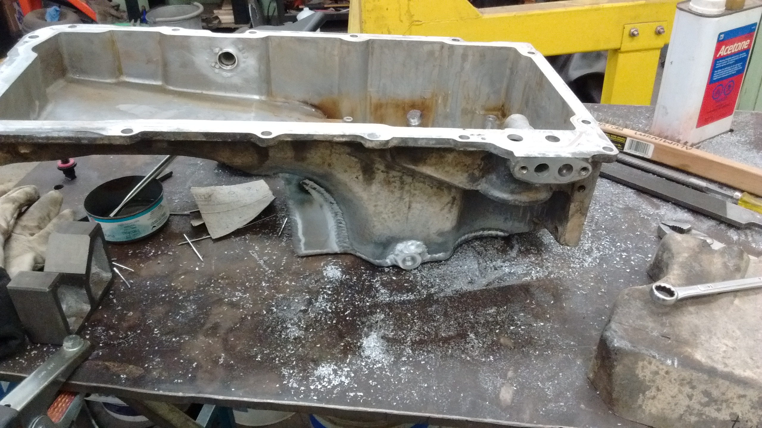
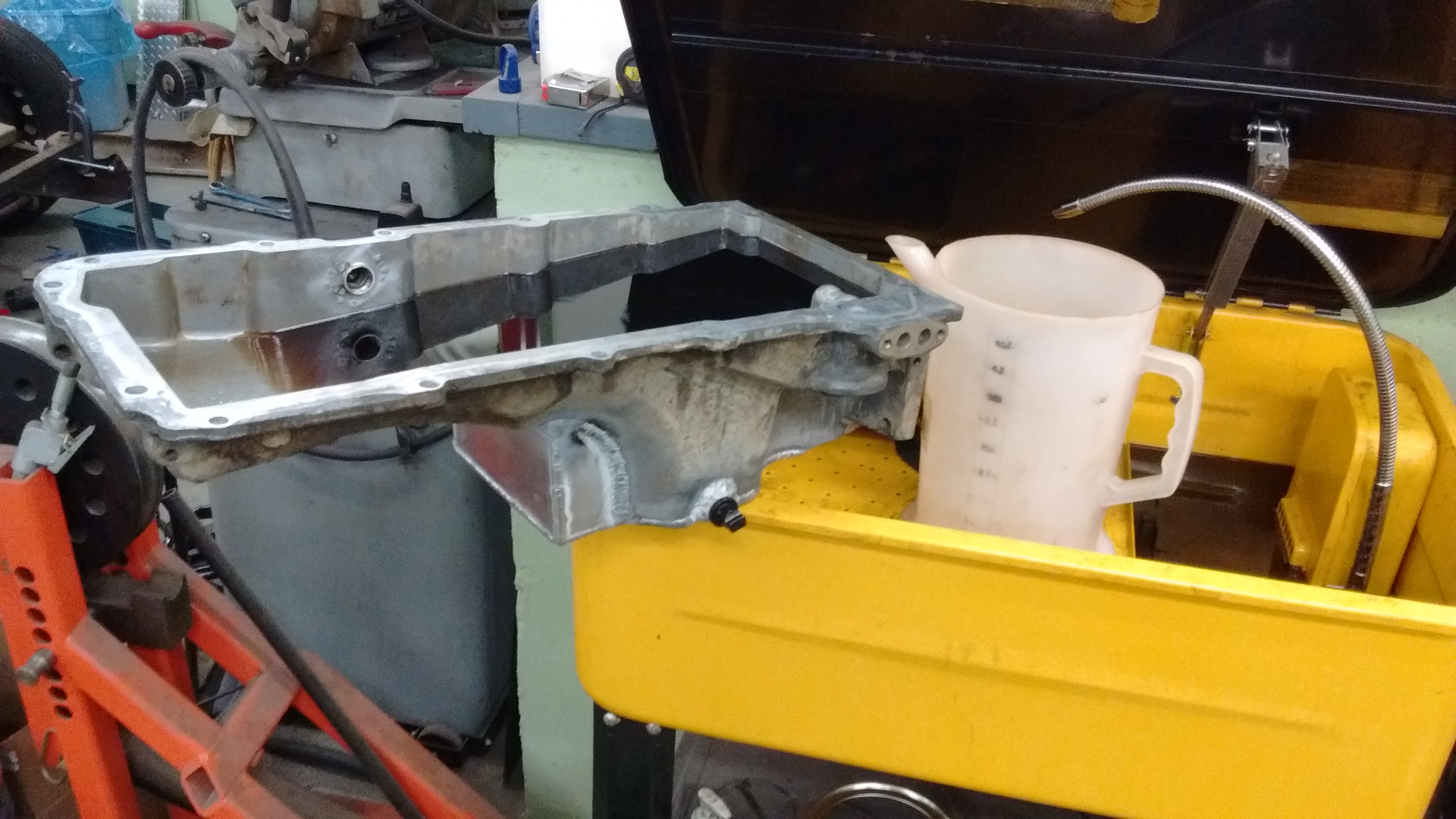
One wee leak at the back which I fixed. This is 6.5L of solvent in the pan; good capacity.
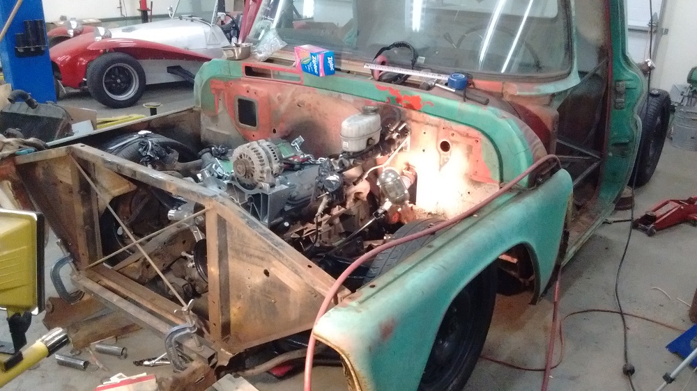
Motor, trans, and cab, at ride height. Oil pan flush with bottom of frame.
Fabricating Motor Mounts
I shoved the motor around until it was centered in the frame rails, and just far enough away from the firewall that I probably could get the heads off the head studs without dropping the motor or pulling the cab. You know: serviceability.
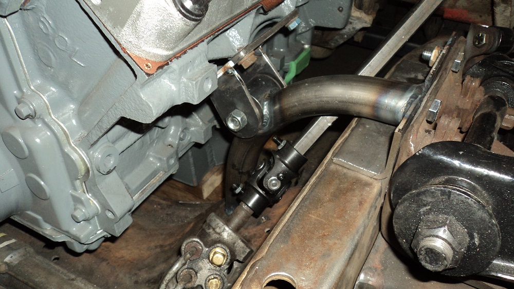
Finally got motor mounts tacked together. I initially tried to mimic the 63+ mount in tube, but attaching to the new (higher) upper control arm mounts to give it rigidity. Worked fine on the passenger side, but not the driver’s side because of the steering – nothing seemed to work well.
Then I thought if I ever wanted to ditch the turbo and run headers, that tube would be in the way, so…..
Simple “ears” off the crossmember, basic plate on the motor, the tubing will be gusseted.
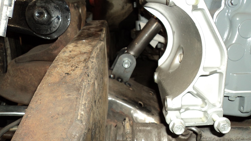
Driver’s side got the ears further down to clear the steering. Not symmetrical (boo), but it will work (yay).
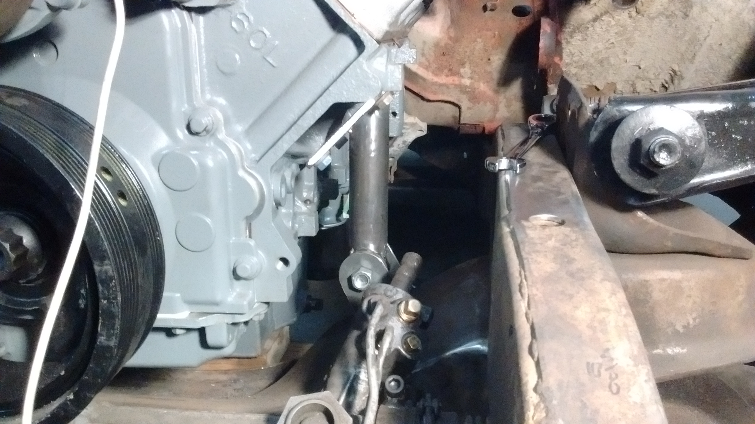
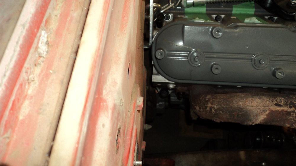
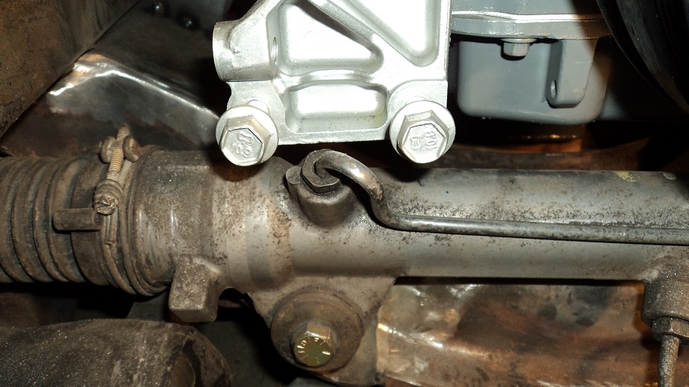
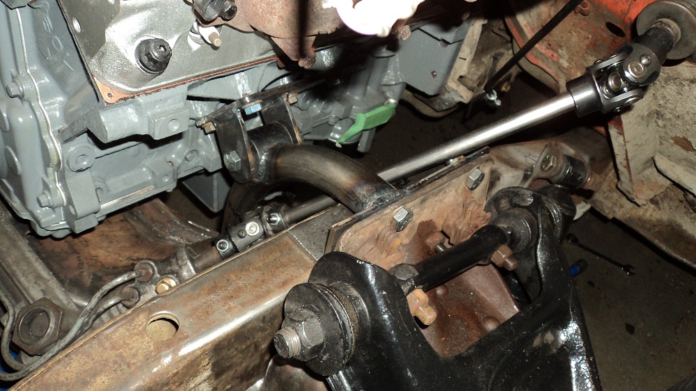
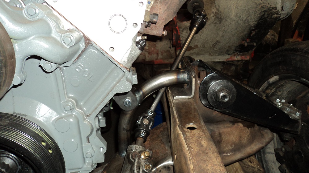
Not a lot of clearance between the motor and the rack:
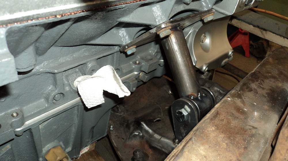
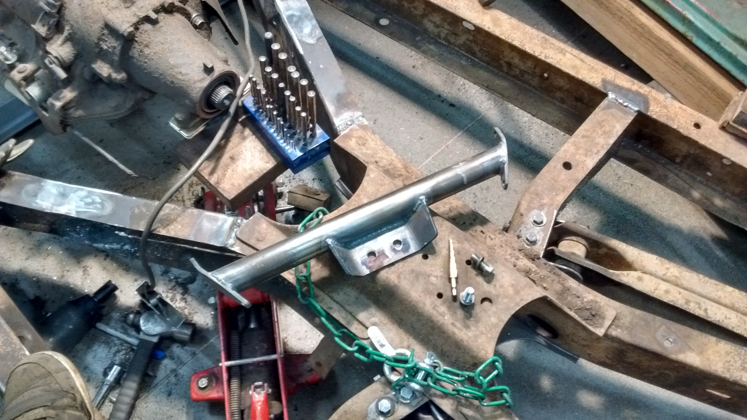
I was not happy with those motor mounts. I am happier with these. Plates are 1/4″, 1.5″ tube. Angle piece at the top was cut from the shipping braces my Rotary lift came in.
Driver’s side welded and installed, passenger side ready to be tacked.

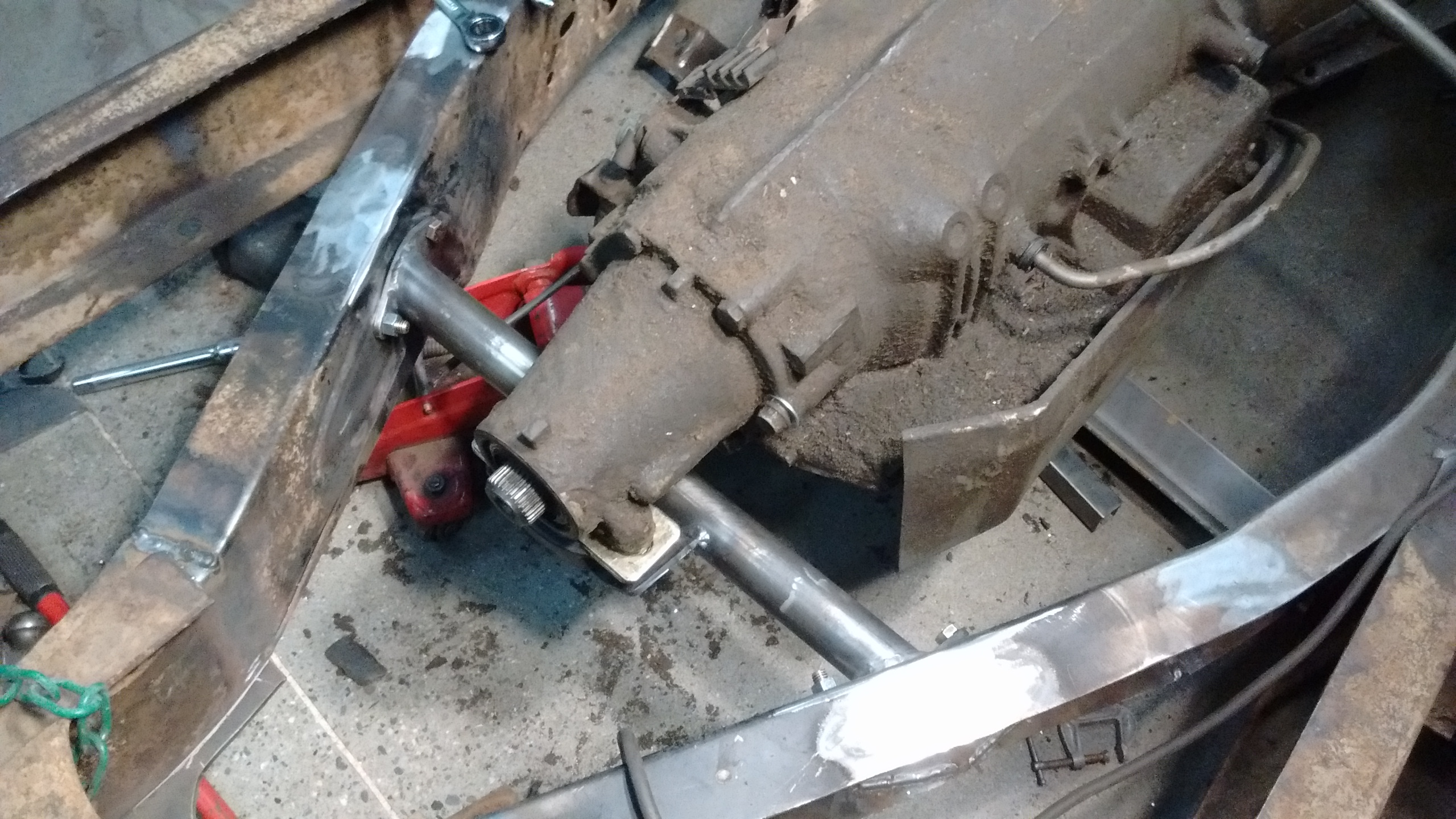
Fabricating Transmission Mount
Trans mount is 1.5″ tube, with 3/16″ flanges, 3/8″ bolts. Driveline is about 3° down, and none of the driveline is below the frame. I will -probably- have to modify the top of the frame “X” (and cab floor?) for driveshaft clearance.
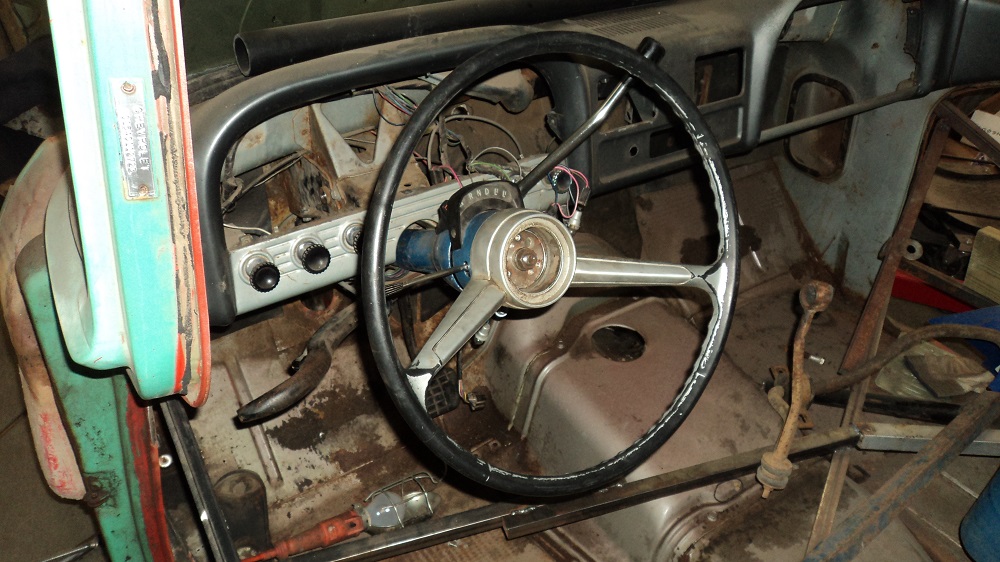
Fitting a ’68 Auto Column
I bought a used ’68 column auto shift.
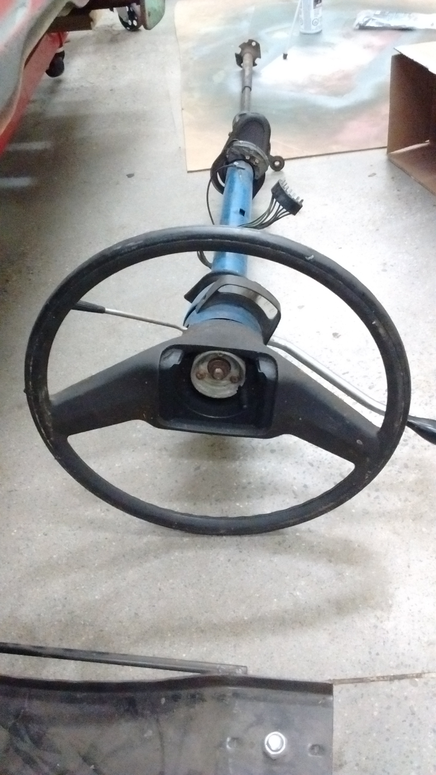
The “new” column didn’t shift, and the wheel on it is not the right wheel, and the horn apparatus on the ’61 does not work with the ’68 column.
I took the column out of the ’61, took both of them apart, and compared everything inside. The ’68 column is longer, but for the most part very similar. I could put the column shift parts in the ’61 column with very minimal work, or I could adapt the ’68 column to fit the ’61 dash. I could even probably shorten the ’68 column too.
One disadvantage of keeping the ’61 column, is the signal light switch was designed by Rube Goldberg, and it may be beneficial to keep the later stuff.
I decided to keep the ’68 column, modifying it to use the ’61’s mounting system. I will figure out how to work the ’61’s horn to operate on the ’68 column.
It took a LOT of time mucking around with the column to figure out why it didn’t shift, and how it should go back together. But it’s done, and it’s in.
The spline on the column is the exact same as the spline on the Fox Mustang rack. Interesting. Another 3/4-36 spline u-joint on the way. Anyone need a DD-to-DD u-joint?
Also removed the clutch pedal.
Fabricating Shifter Linkage
Shifter is hooked up to the trans. PRND32 all line up, and 1 is just off the screen. It’ll be fine. I -will- need to build up the P/R peg, as it’s quite worn and too easy to slip out of park.
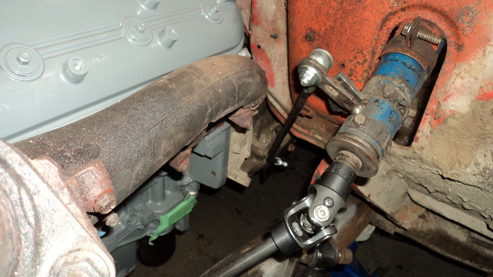
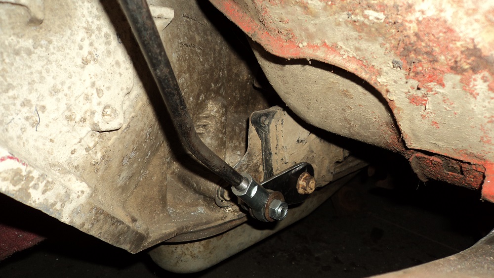
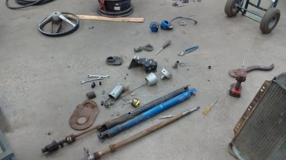
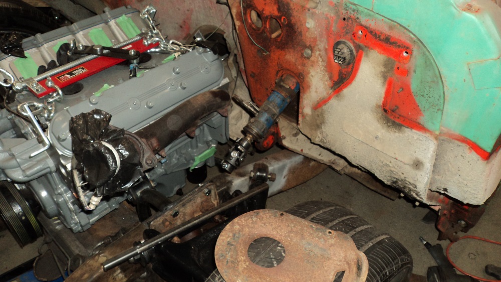
I got the steering connected, and had to chop a bit of the frame to do so.
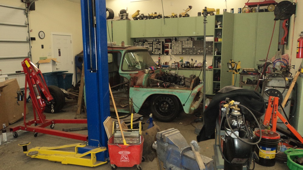
Ride height also appears to be 11″, measured from the front wheel center to the fender edge. That’s, um, pretty low….
Power Steering & Hydroboost
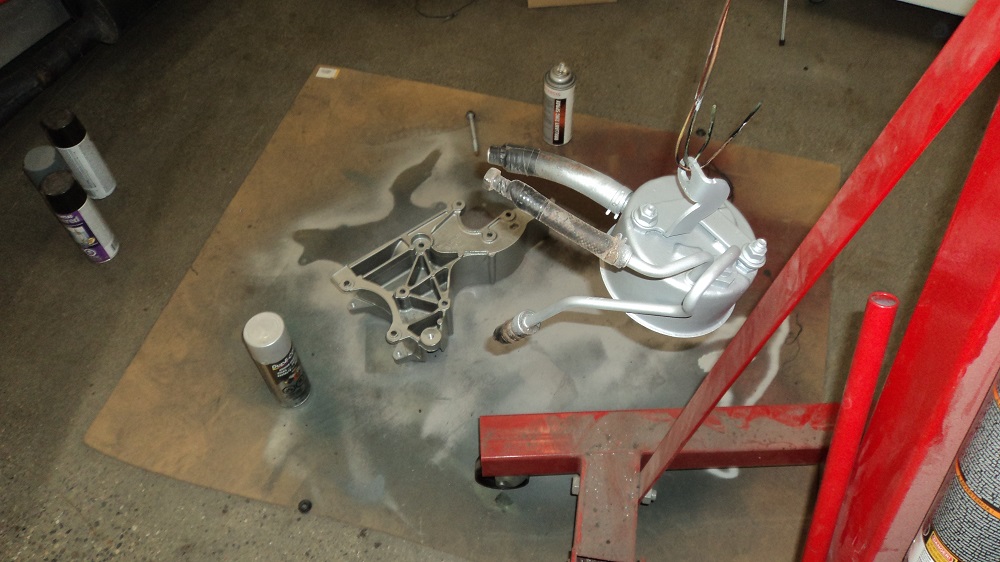
Blasted and painted the power steering pump body, as well as the accessory mount.
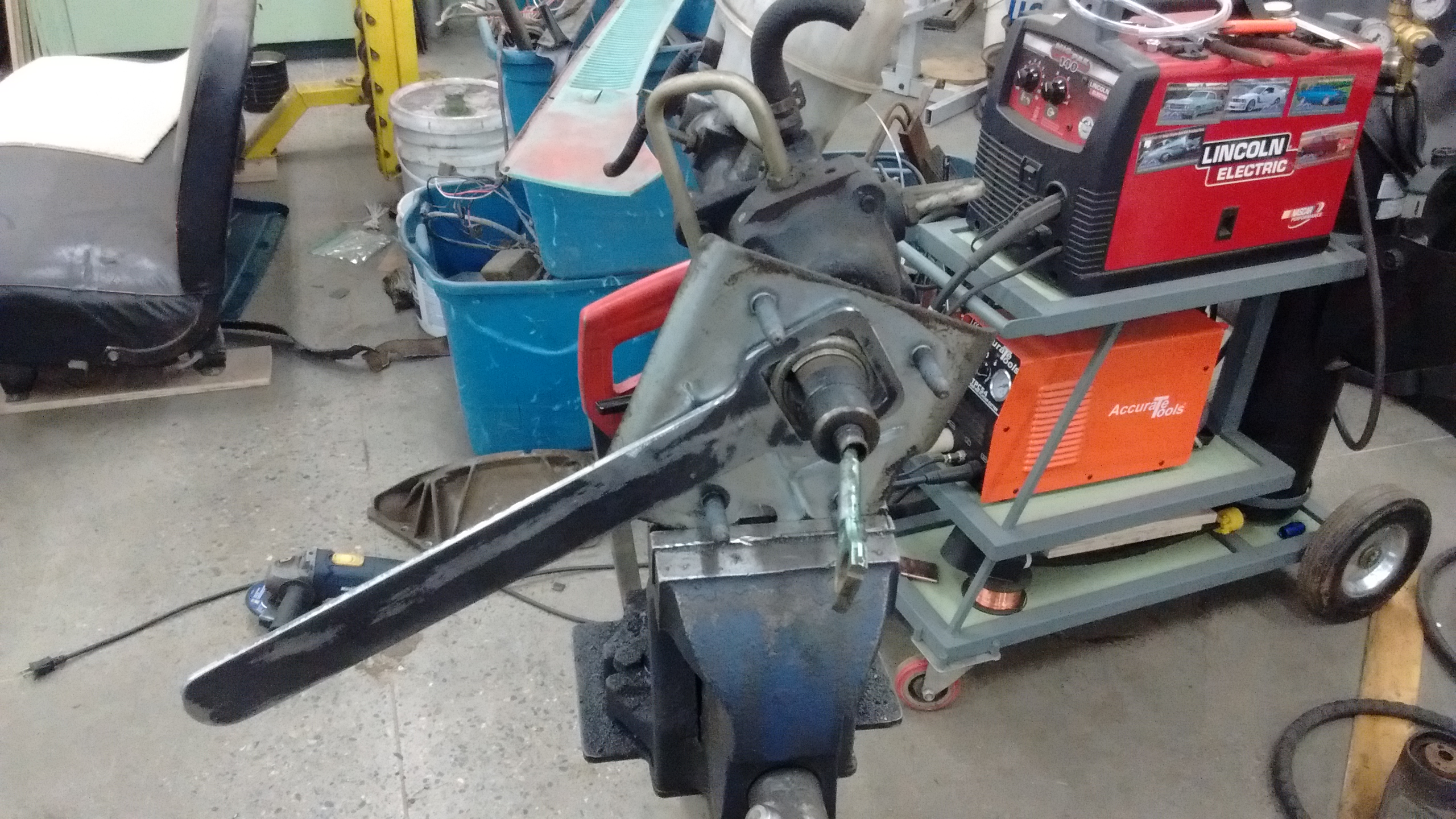
About eight iterations of Hydroboost mount brackets, trying to find something I like, and kind of copying what others have done before me. In the end, I will likely do a very simple bracket that bolts on where the original clutch/brake master sat (blocking off the clutch hole), and have the Hydroboost mount to that. Need to make a BIGASS wrench though.
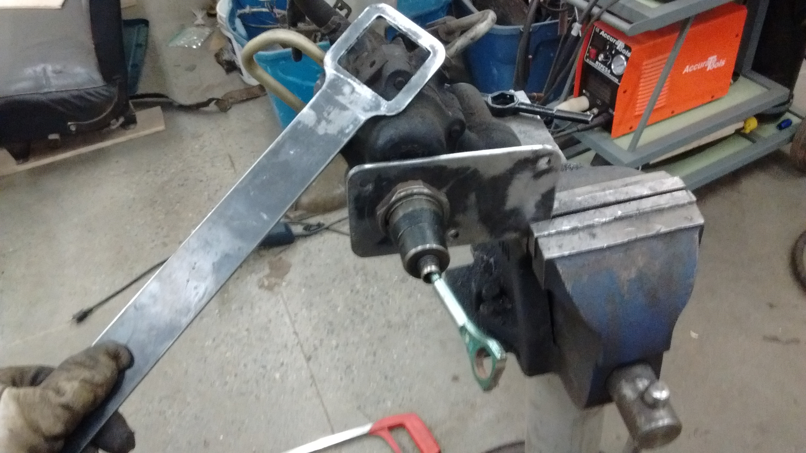
Got the Hydroboost mounted. Just have to alter the link to the brake pedal.
Also mounted the PS/Alt bracket, after a duck-shaped coating of Plastikote Aluminum engine paint. PS pump was blasted and sprayed with Zinc and then Tremclad Hammered finish. Pulley is black brake caliper paint I had.
Pump reserviour was the nicest one I found at the wreckers, but lo and behold, it was beginning to rot out under the powdercoating. This is turning me off of powdercoating the frame. Reserviour was blasted, zinc’d and will get a coat of Tremclad Hammered tomorrow.
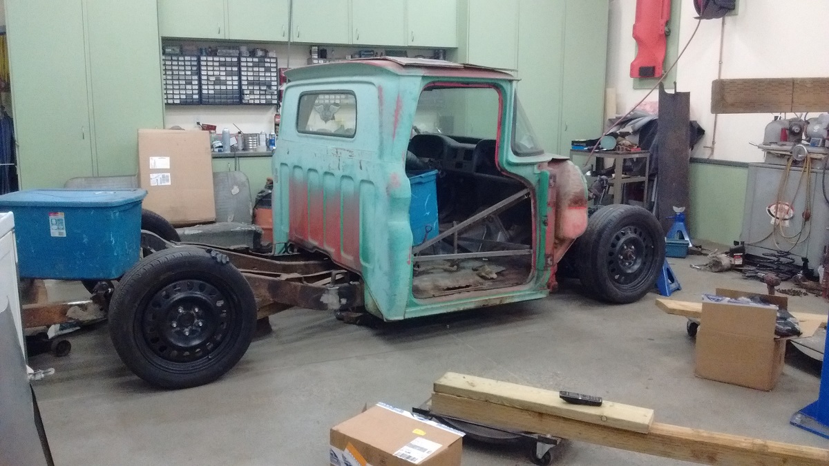
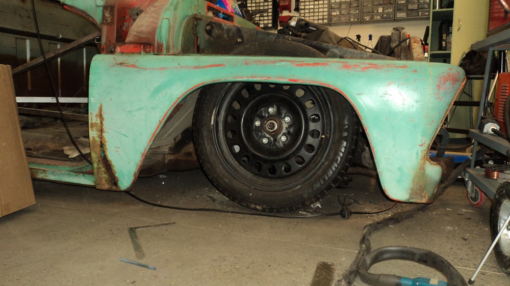
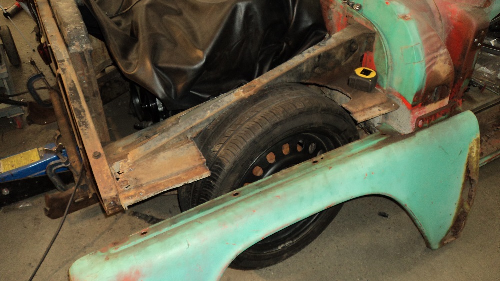
I put the “non-bent” fender on the driver’s side and was pleased to dicover this truck is NOT too low after all – it can steer! It’ll be DANG low, but it will steer easily AND be able to hit bumps at the same time. Yay!
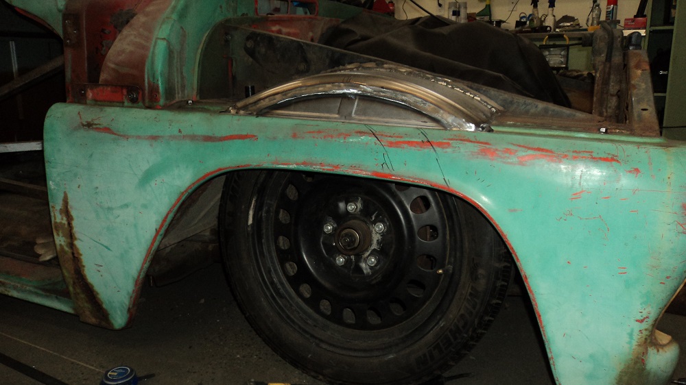
Fender Tubs
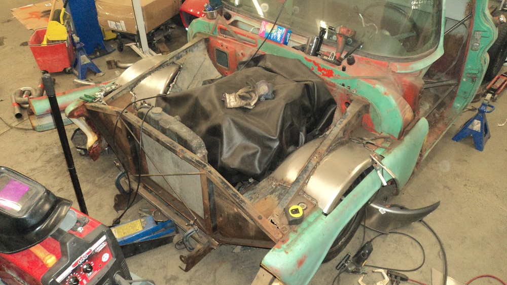
Trimmed the inner fenders to clear the shock mounts, steering shaft, and raised crossmember. Placed nose just to see how to fit intercooler. And AC condenser. And trans cooler. And PS cooler. And oil cooler. And cooling fan. Going to be an interesting challenge. I quit and went in when my brain was full.
Oh look what was on sale at Princess Auto today! I bought three, so I can make two. My plan is to make decent inner fenders, so keep road crap out of the rust areas.
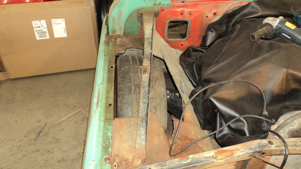
I need to know where the tires are going to end up, so me and Mr. Plasma got happy.
It will ACTUALLY STEER like this, full lock-to-lock, with the control arms on the ground. Inner fenders will be patched up, outer fenders need to be notched 2.5″.
NOTE: I would not do it exactly like this again – details below.
Inner fender #1 tacked together. Some more wee patching to do.
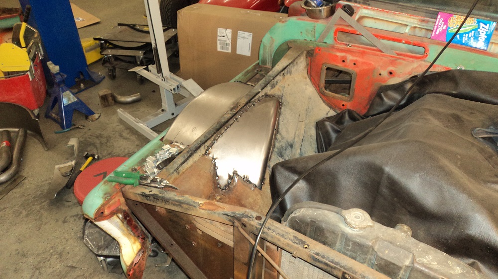
Filler panel for the inner fender. The outer fender will be attaching to it from underneath, hence the holes.
Wow. I have SO many hours into these inner fenders. Oh my gosh. And I’m out of MIG gas, on Christmas day.
DETAILS:
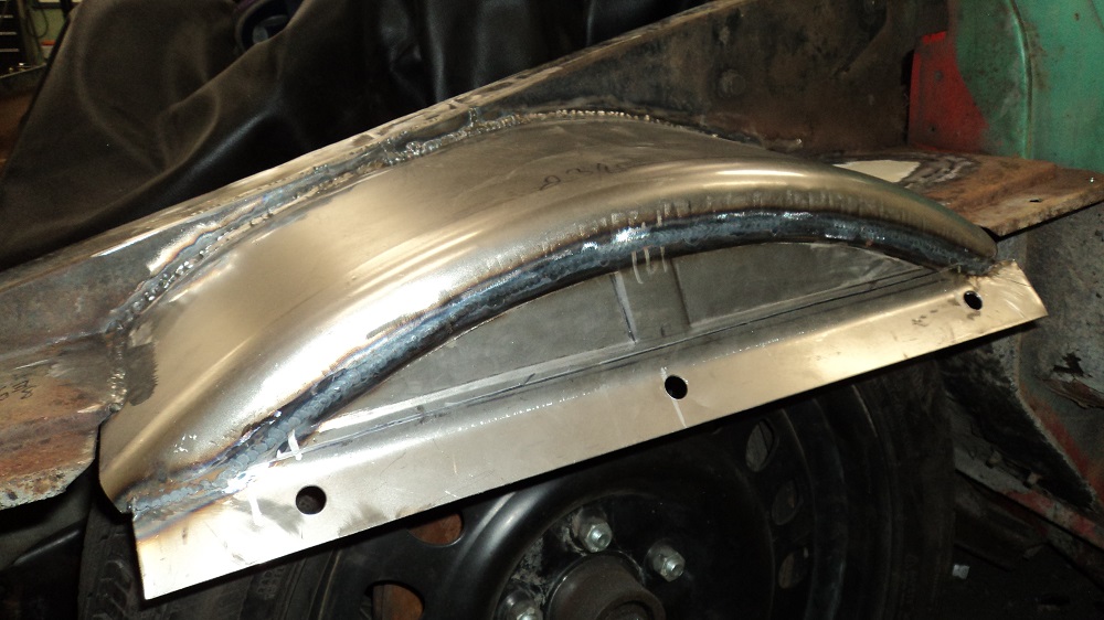
Welding wheel tubs this way introduces a LOT of shrinkage to the inner fender. You really want to minimize the amount of weld bead you are putting down. I think I would fabricate the tubs with tabs on the sides, which could then be plug welded (spot welded) to the fender structure, much like the entire truck was assembled from the factory. This would make everything maintain its shape better. This coming from future me (from page 10), who has finished repairing all the rust in the entire truck.
Turbo Planning
To mount the intercooler, I need to remove the rad support X bracing and chop some metal out of the vertical supports.
To fit the AC Condenser, I need to move the rad back an inch.
To mount the Turbo, I need to decide if I want to go mild steel or stainless on the crossover, and if I want to go 2.5″ or 2.25″ (though it may not really matter). And decide how I want to clear the PS pump and reservoir.
Picked up three 2.25″ 409 stainless J-bends to do the crossover, and also picked up a big cone filter for the turbo so I can accurately place the turbo. The wheel tubs needed to be built to accurately place the turbo.
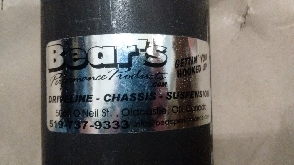
And exciting news, the driveshaft arrived. 1350 ends and high-speed balanced, from Bear’s Performance out of Ontario.
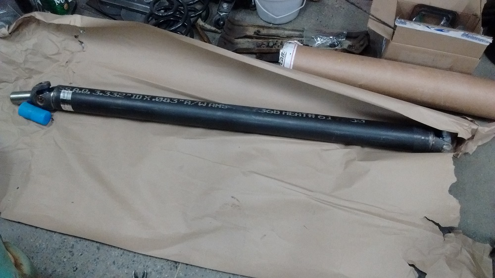
And I will need to take the cab off and cut some more out of the frame to fit the driveshaft.