[ Start ] [ Index ] [ Parts List ]
In Which I Modify The Suspension And Steering
I had to debate how to deal about wheels. The Jeep Grand Cherokee wheels that I have, have a fairly small center bore. I could bore the wheel out to fit the GMT400 brakes, or I could turn the hub down to fit the wheels.
I tried opening up the wheel center using some stacked hole saws and a wrist-breaker drill (I do not have a lathe than can spin an 18″ wheel), but it went awful, and likely couldn’t be balanced since the center was no longer true. That was a dumb idea. I don’t know who thought that up, but what were they thinking?! I won’t do that again (but I did correct the wheel center to be true again)

9″ Ford Axles
I had bought a 9″ Ford axle from a friend. It was from a 1980 Van, and has a Nodular center section.
I inquired at two different machine shops about getting the 9″ axles re-drilled to Chevy 5×5 bolt pattern and hub diameter.
One shop (in business for 75 years) had no idea if it could be done.
The other shop (45 years) said worst case (having to weld the old holes closed), it would be $300 per axle. That’s $600CDN, or about $450US. I can get Moser to MAKE me new axles for that…..
The cut-to-length 9″ axle shafts I ordered from East Coast Gear Supply have a hub diameter that is smaller than the Jeep wheels, so I cut the front hubs down to match the axle shafts.
In theory, once these hub/rotors are no good, I’ll machine the rotor off, and use Grand Cherokee SRT8 rotors for a big brake upgrade. It works in my head, dunno if it will work in real life.

’87 Blazer tank won’t fit a shortbed, so that went back.
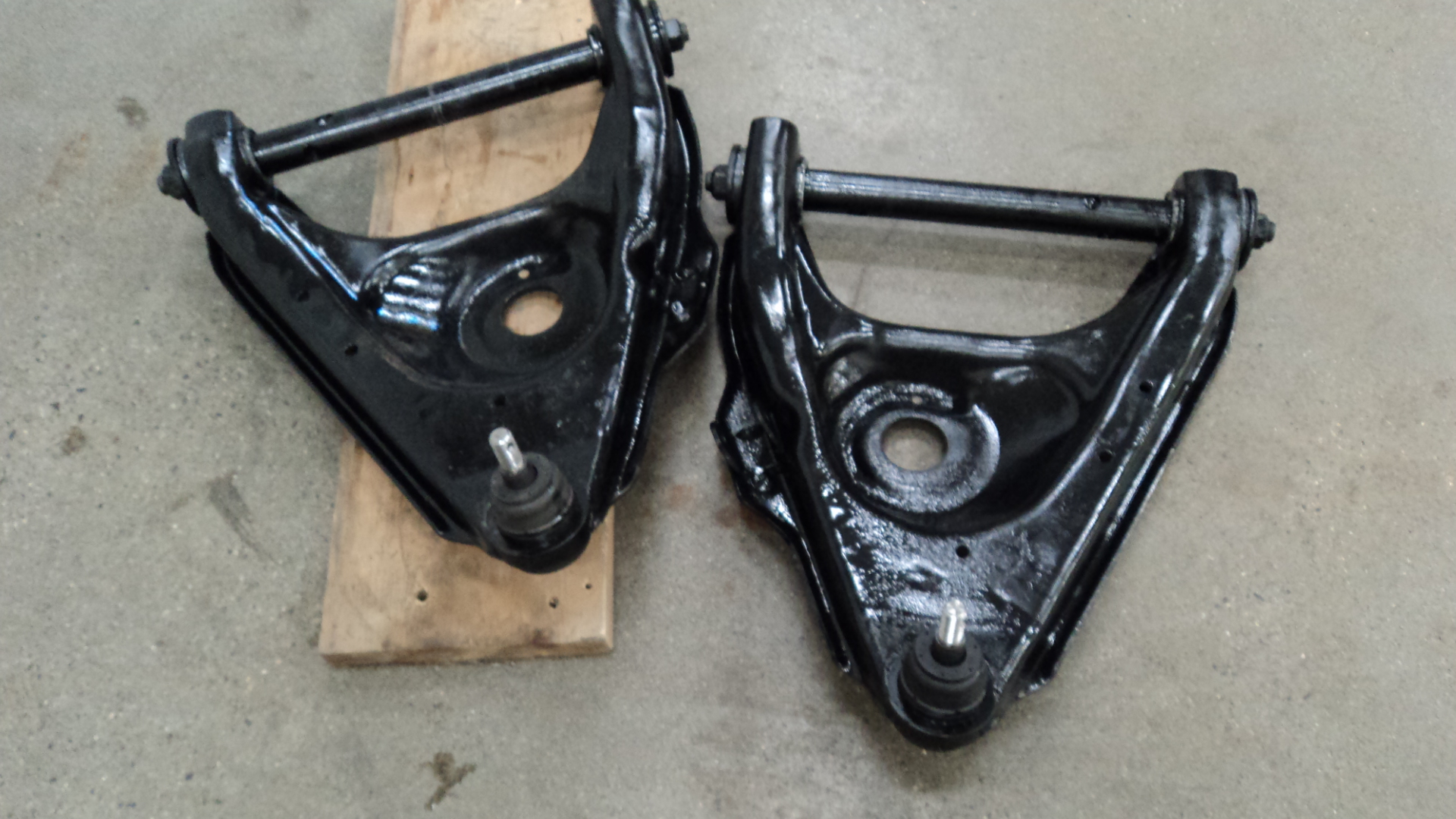
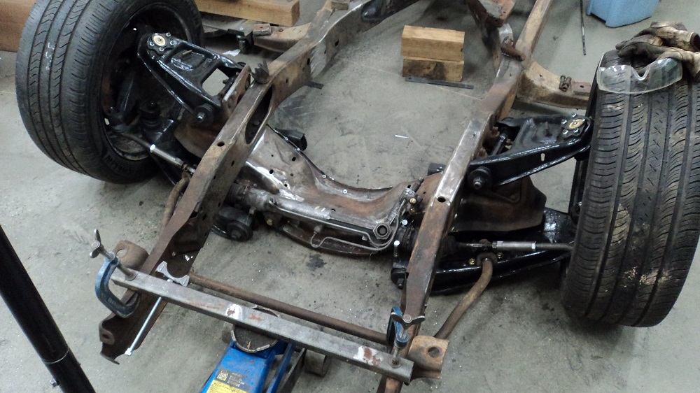
Sandblasted the upper and lower control arms and cross shafts.
Machined out the 73-87 balljoint location and welded in a mounting ring for the 88-98 balljoint, offset to the outside 1/2″ each side.

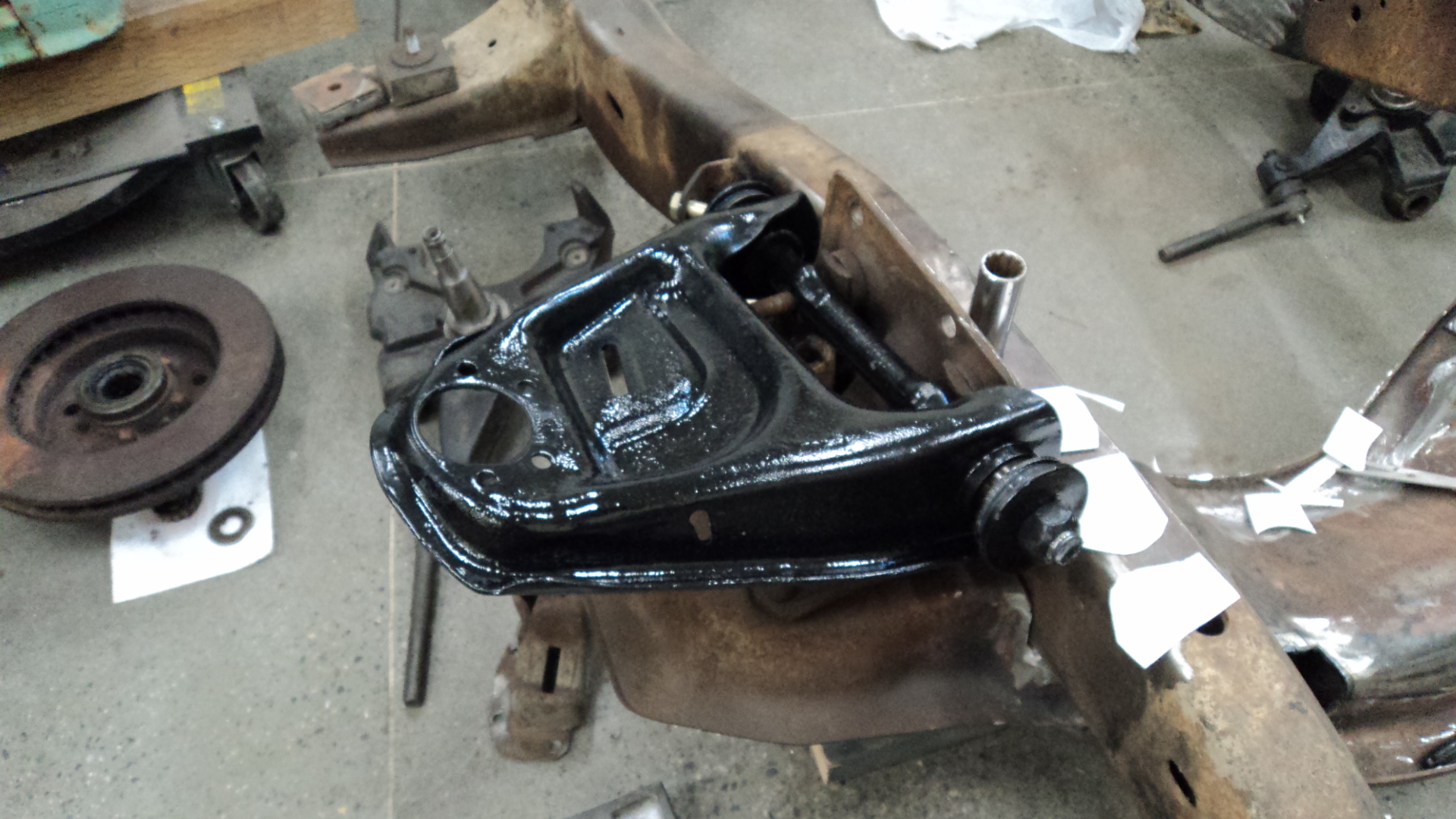
Sectioned the forward arm of the lower arms to make more room for the Fox-body steering rack.

Bought a gallon of Epoxy Primer.
Pie cut the upper arms, reducing the ball joint mounting angle by 10°. Should prevent locking up the balljoint should I decide to go air ride.


Spent a week on Vancouver Island, which was good – I needed to figure out the rack placement.
I had to remove the driver’s side eye mount, but I will replace that with a pipe clamp sort of arrangement.

Two coats epoxy primer, then 2K Chassis Black:

I forgot to paint the lower arm u-bolts, but I still had some epoxy mixed up, and there was JUST enough left in the chassis black can to finish those today.
Also disassembled the front clip of the truck. Only broke 1 bolt 🙂
Summit-brand Poly Bushings (they look and feel like Energy Suspension, and even have ES part numbers cast into them… just saying) and lower ball joints installed. Still need to bolt in the new upper ball joints. These are 88-98 ball joints in 73-87 arms, with lower ball joints moved outboard 1/2″.
One bushing sleeve cocked and buckled, and after I finished swearing at it, I was able to remove the sleeve, unbuckle it, and re-shape it again and put it back together.
A question came up on a forum where I’ve been sharing this, and I thought I’d share it here:
Why are you using 88-98 lower ball joints?
Good question. It’s kind of a hodge-podge snowball of staying under budget and working with what I have and what I want.
1. I will be running a turbocharged LS, planning on 600-650hp to the wheels.
2. I’m not happy with the durability of the 12-bolt in my ’77.
3. An 8.8 is narrower than I want, and I want to run the same size wheels front and back.
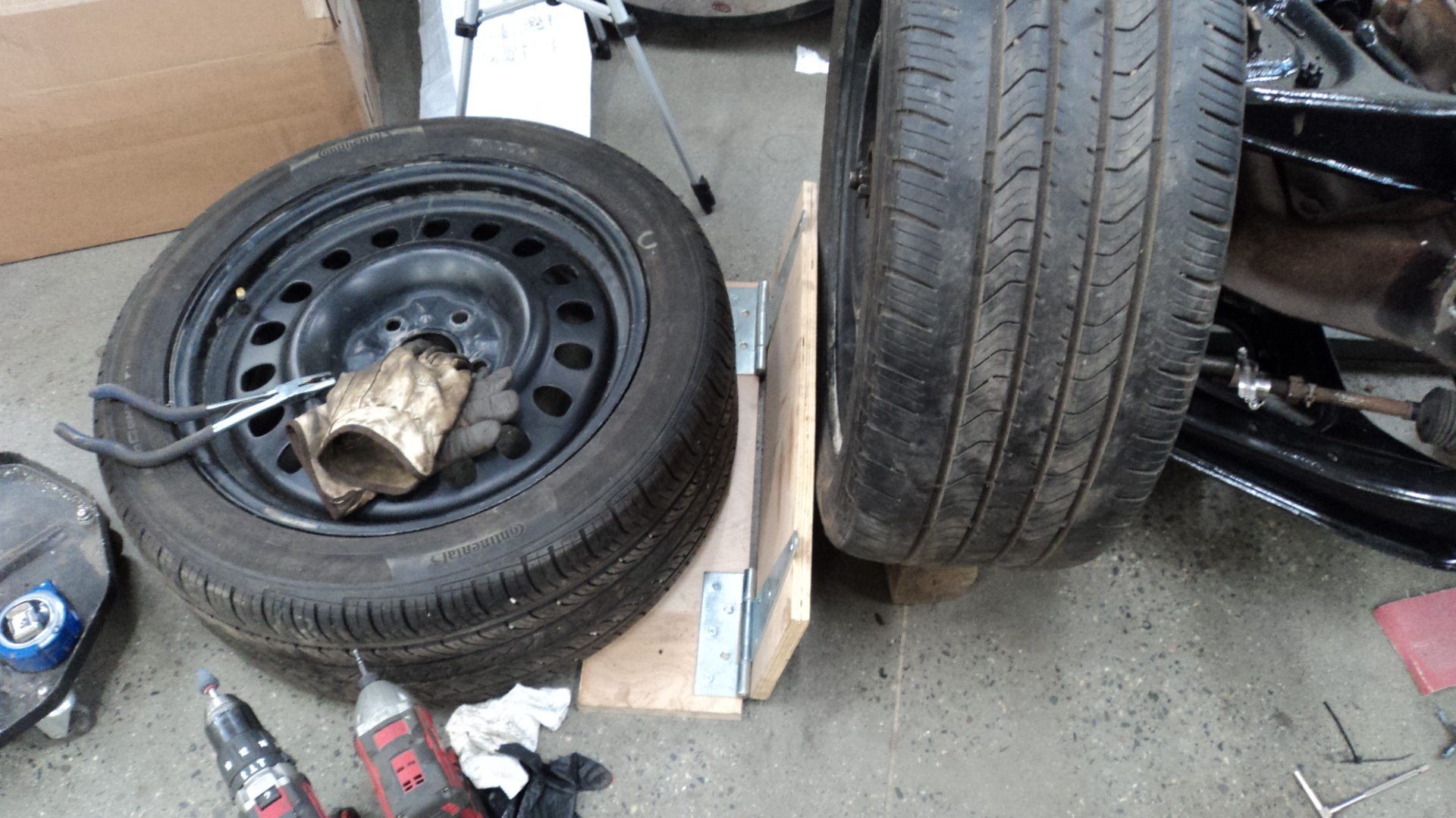
4. I’ve seen people on here using Jeep wheels in 18″ and 20″, but they need to use spacers. I like the look and the idea of those wheels, but I do not want to run spacers. I got a sweet deal on some 18″ steelies.
5. I got a sweet deal on a 9″ axle which I could narrow, but with the fwd-offset of the Jeep wheels, I don’t need to – the wheels would be placed in approximately the same location as stock, which provides good clearance for turning while riding low (I have not decided if I want to air bag it or not).
6. The width of the 9″ requires widening the front track quite a bit, which means relocating the ball joint location, or fabricating new upper and lower arms.
7. I got a sweet deal on a set of 2″ 88-98 spindles, and since I need to relocate the ball joints anyway, I might as well make them work with the spindles. They are a bigger ball joint as well, and the 73-87 ball joints are not awesome. Plus, the 88-98 spindle seems to have more Steering Axis Inclination (SAI), which means I don’t need to alter the upper control arm at all (saves work), and my calculations indicate I only needed to move the lower ball joint 1/2″, which is (theoretically) a lot less than if I used 73-87 spindles.
NOTE: a larger SAI might have been employed by GM to reduce the scrub radius (the distance from the steering axis to the wheel centerline, at ground level). Ideally you want to be within 10% of the wheel width for scrub (in my case, 0.75″ would be ideal).
The 73-87 spindles have a fairly LARGE scrub radius, and my guess is GM tried to reduce it by increasing the SAI. A smarter way is to run more backspacing (FWD-style offset).
The downside to a high SAI is you lose significant camber on turns (watch any MacStrut car). You then need a fairly high amount of caster to counteract that dynamic camber loss on turns. Lots of caster is almost always good, but can un-weight the inside rear wheel on a corner, resulting in wheelspin.
8. (I didn’t plan this one) The 88-98 spindles mount the tierod below the steering arm (73-87 is above), which improves steering rack placement. Many kits that use the 73-87 spindles run a heim joint for a tie rod, mounted under the steering arm (easier to reduce/remove bumpsteer for sure). I don’t want to run a heim joint, I want a proper tierod.
I think that’s most of my train of thought.
Make sense?
And honestly, I like “the build” and “creative solutions using OEM parts” and my labour is free.
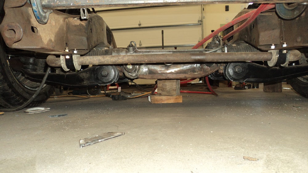
Rack & Pinion Steering
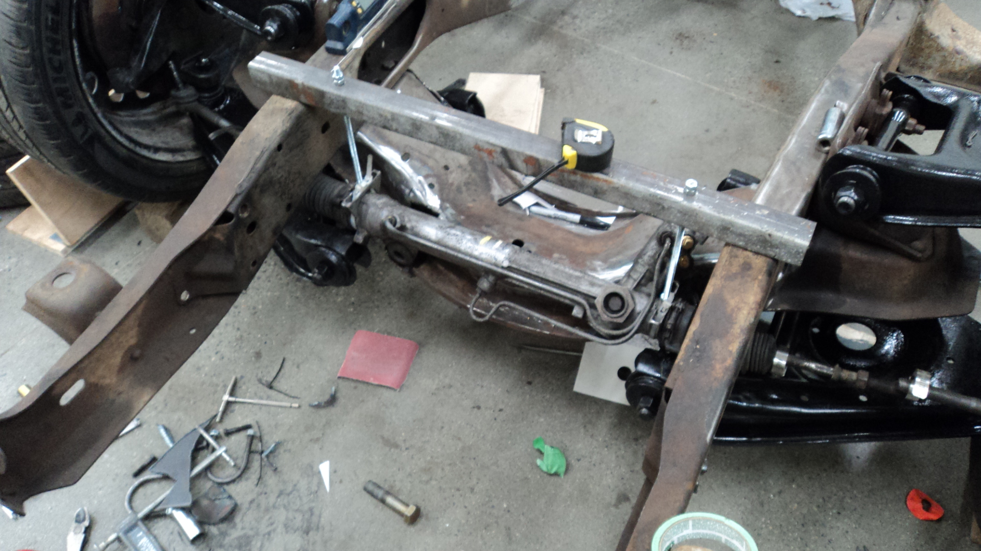
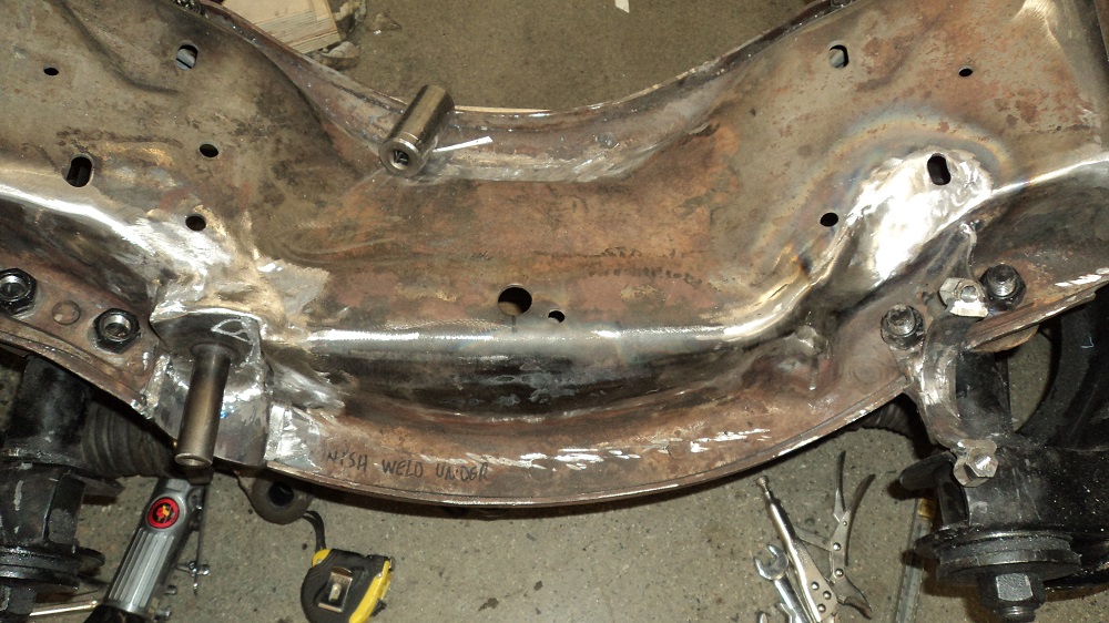
Spent a number of hours finalizing the Fox-Body steering rack to minimize bumpsteer. I had to take a small chunk out of the crossmember where the passenger side lug goes, but nothing I can’t re-shape and repair.
I set everything up at ride height, and checked for any toe change at a full 3″ bump and 3″ droop, using this fancy device to see the change.
I got it down to a fart of toe in on both bump and droop, so I took the inner tie rods off and shaved 1/16″ off the end of the rack threads, which now gives me a tick of toe out on bump and droop (dang!), which is more preferable than in (oh, well – yay! then). I guess I can shim it more precisely if it is even a perceptible problem.
Addendum: Nope, I was measuring inaccurately. More details to follow.
Simple apparatus for adjusting rack height shown below. Square tube supporting Redi-Rod which is threaded into muffler clamp saddles (had to use zap-straps (zip-ties) to hold the rack, since I didn’t have any 2.5″ clamps). By threading the Redi-Rod up or down with a nut, I could position the rack, then test for bump steer.
Honestly, fretting over wee bits of bumpsteer is a waste, in my opinion. If anything in the setup changes, nothing will be optimal and you have go in again.
I was, however, pleased to discover that full lock of the steering doesn’t run the wheels on the control arms anywhere. Yay!
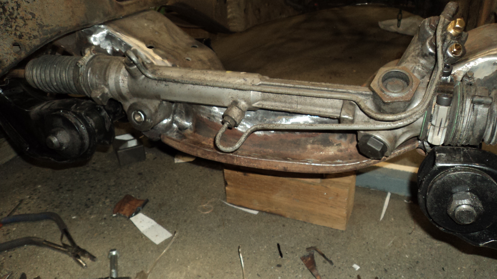
Passenger side was fairly straight forward, I made a 3/4″ peg to hold the original lug of the Fox-body Mustang rack (mounting bolt not shown). The driver’s side lug was machined off, the housing rounded, and a “clamp” mount to hold the rack to the crossmember. The mount took two attempts to make it work, and I’m mostly happy with it at the moment…..
An interesting aside, when you’re trying to optimize steering rack width and location to minimize bumpsteer.
Ideally, you want everything set: ride height, caster, camber, and toe, and then optimize for minimum bumpsteer. Sounds easy, right?
Except if you end up changing ride height, caster, camber, and toe, and then your rack is no longer in the optimal location. What the heck?!
Which probably explains why factory cars go so aggressively toe out in bump.
This Longacre Racing Bump Steer article suggests if have to have any, have bump out as it can improve stability on corner entry. Never have bump in.
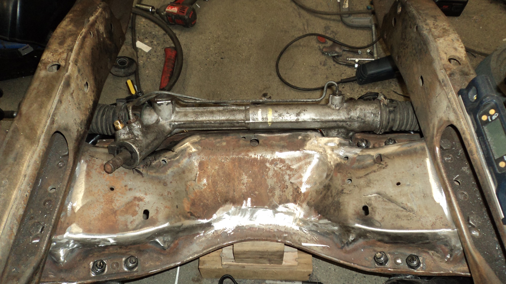
Turned out I was not measuring accurately enough, so I changed my tactic, went “oh crap!” and cut out the entire rack mounting, then tacked it up again with what I thought would work better. Ended up with 1/8″ toe out on bump, and quite a bit of toe-in on rebound.
Then I second-guessed myself, and put it all back the way I had it before, and had a bit of toe IN on bump, but less toe IN on rebound. To fix this, I would have to narrow the steering rack, which I don’t think I can do because it’s a power rack, so I cut it out again and put it back to where I had changed it to, but a slightly different rack height, and now I have zero toe change from ride height to full bump (5″ movement), but some fairly aggressive toe-in through rebound. I’m going to leave it and see. It’s not a race car.
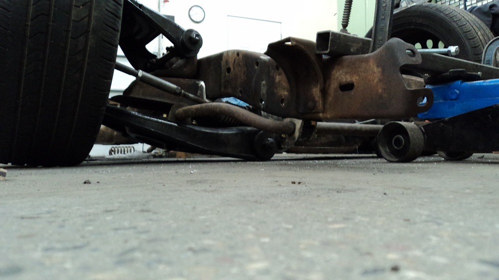
And, I installed the sway bar that came with the crossmember. Had to clamp a section of tube so I can get the jack out from under it.
Yes, that’s sitting on the ground.
And this is why I pie-cut the upper a-arms:
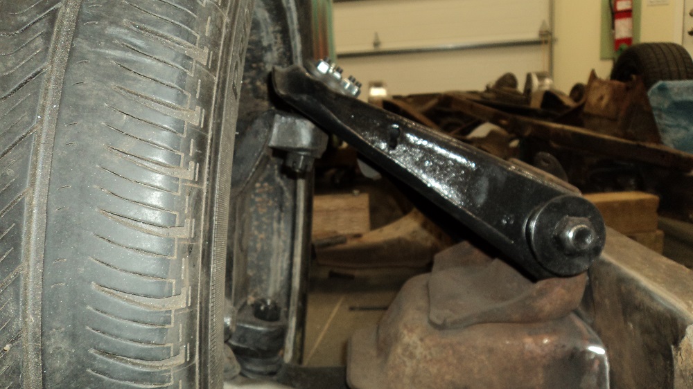
Also cut off the shock mounts, as I will need need to relocate or refabricate those.
As low as it will be going, all layed out:
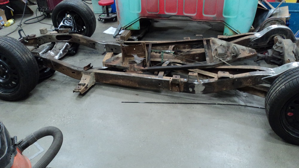
Prepping the 9″
Pulled one of the axle shafts out of the 9″, removed the bearing, seal, and plate, pressed the new studs into the new East Coast Gear Supply 5 on 5″ axle shafts, installed new bearing et al, and installed the axle. Now have one wheel properly bolted on on the back. We’ll see how far I get on the other tonight.
Axle appears to have about 3.50 gears (3.55 if Ford???). Perfect for boost! And saves money, as I only have to buy a limited slip, not that and gears.
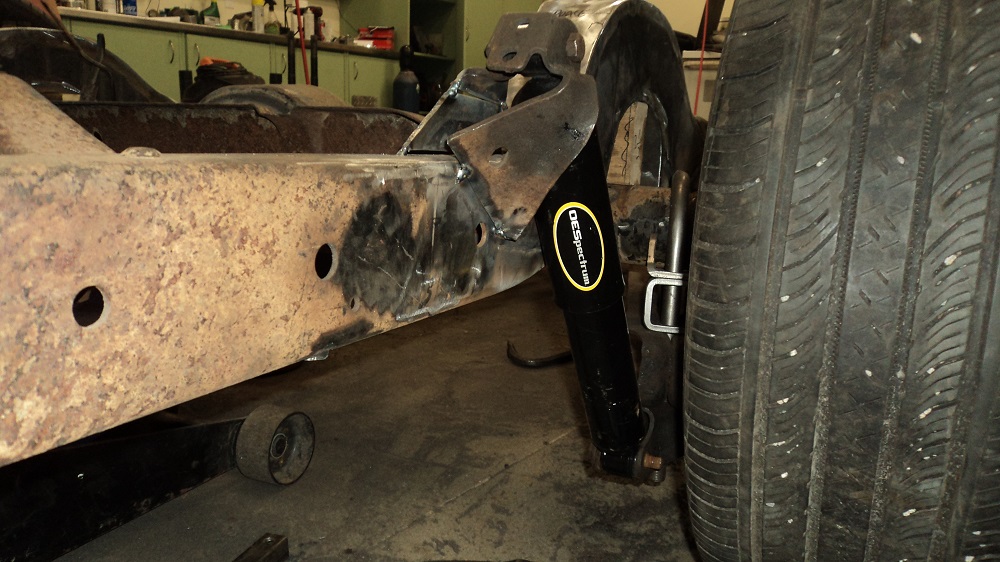
Front Shocks
Front shock mounts are done. I used the ’61 brackets, just relocated. Shocks are OEM squarebody. I set the chassis up at full droop, and positioned the bracket with the fully extended shock 1″ away from the upper a-arm shaft threads. My thinking is this would make shock replacement easier, and in fact, there is still about 1″ shock travel left at full bump.
I also picked up some Energy Suspension bumpstops (ES 9.9101 2.125″ tall) for the front, which will set the chassis a tick over 1″ off the ground fully dropped (you can see one just sitting in a hole on the far frame rail while I fit the shocks).
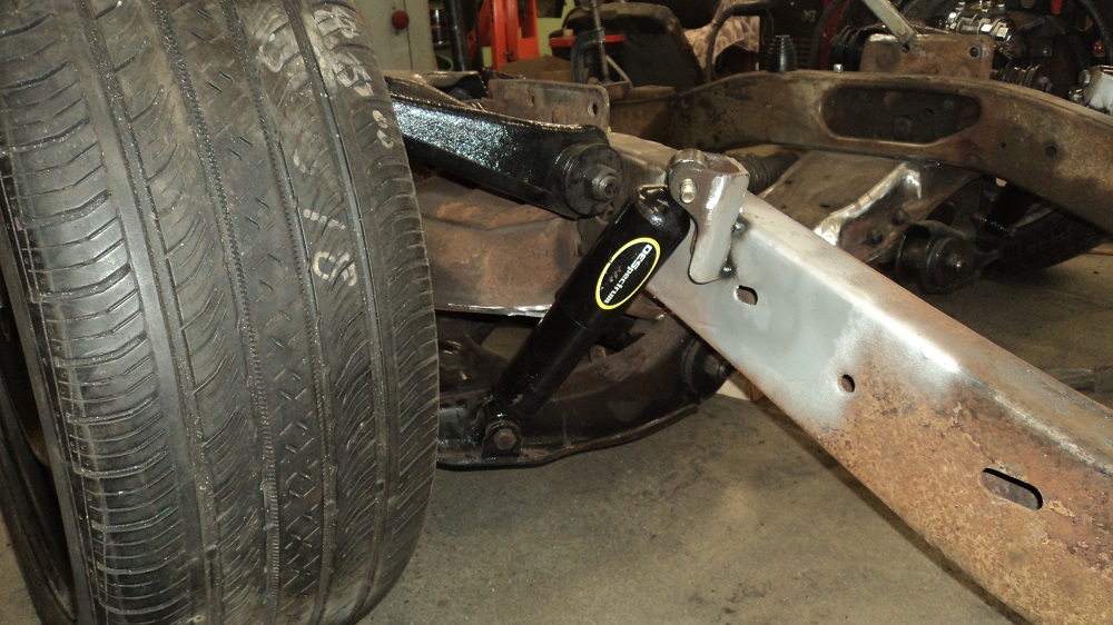
Rear Shocks
Rear shock mounts kicked my butt. Repeatedly.
I’m not really sure why, but Oh My Gosh.
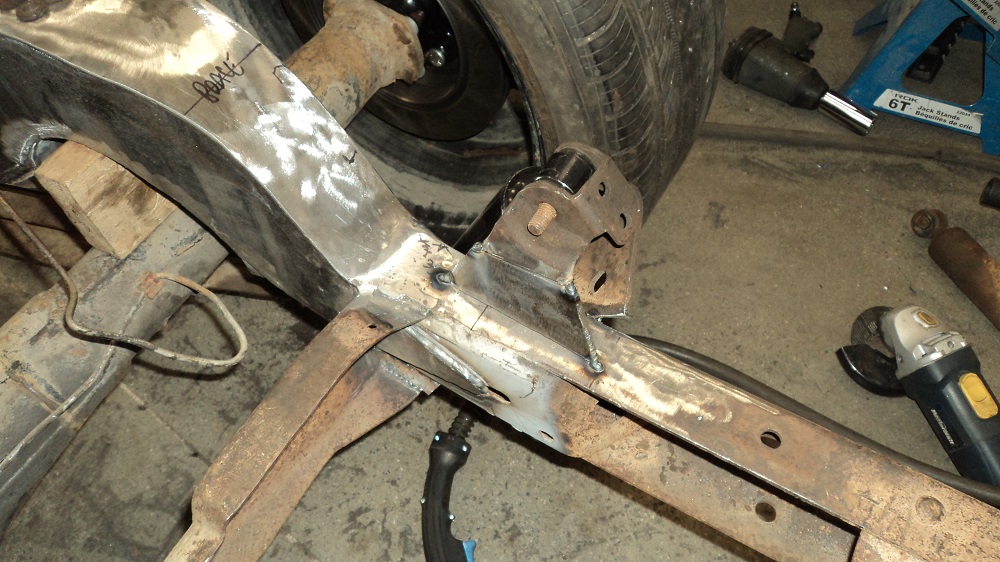
I finally got something figured out. I like the double-shear factory mount, which I had cut off and tentatively moved forward about 5″. But because I want it to ride low, and I want the axle to bottom before the shock does, and because I want the shock to stay reasonably upright, and because I notched the frame 4″, the mount went forward AND up.
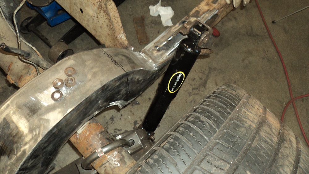
Yes, these shocks are leaning back, but this is how the factory did it. In 63+ GM put the shocks ahead of the axle, angled inward at the top, and angled forward. There are many people who alter the 63+ bracketry to get more travel and less angle out of the shock mounts, as well companies that will sell you the same thing. One company (No Limit Engineering) sells brackets that essentially duplicate the 60-62 mount, and everyone who has installed the kit has loved the improved handling, so, I’ll give keeping it a try.
I was all giggly that I was using shorter 73-87 4wd front shocks for rear shocks. Turns out they are the same as the 63-72 rear shocks anyway. Figures.
Once I had the rear shock mounts done, I started second-guessing myself. I have ride height set with the front crossmember 5″ off the ground, and the frame at the back of the cab 6″ off the ground. This puts the axle (with 2″ blocks) about half an inch into where the frame used to be. This is not where my 5″ drop springs are going to put the axle, so honestly, my springs will be too tall. Instead of cutting it all out again (there were four or five versions of shock mounts, each one kicking my bruised buttox in the same place), I’m going to leave it for a bit. Once I have the body back on and can see how it sits with actual springs in it, I’ll decide if I leave it, run 6″ drop springs, or do a 3″ block. If I change the spring, the shock mount stays. If I do blocks, the shock mount has to come down.
Front end Friday:
I picked up another set of 18″ Grand Cherokee wheels, this time for $50. Good for winters.
I also placed the S10 Blazer tank on the back of the frame, and it looks like it will work great, and I can still run a hidden hitch!
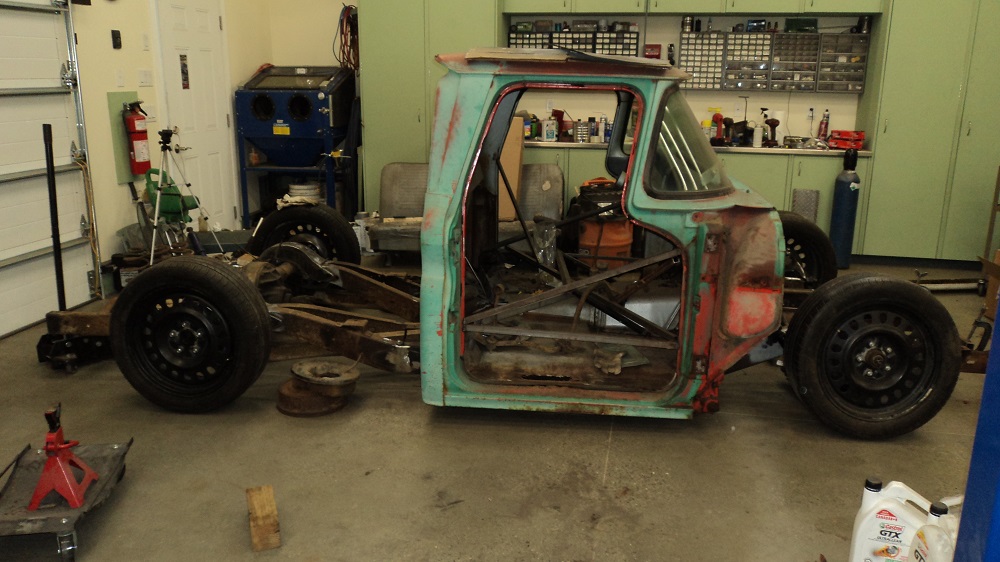
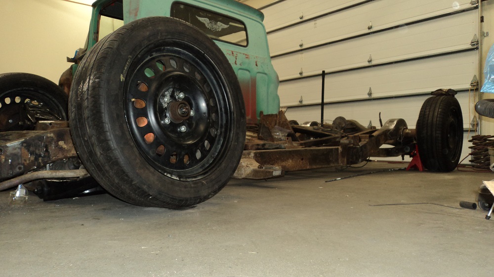
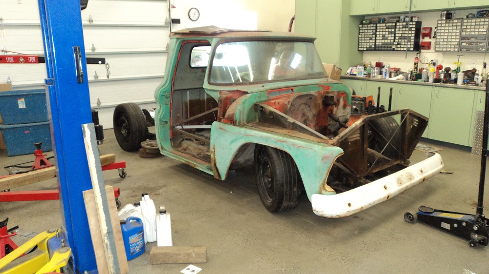
Test Fit
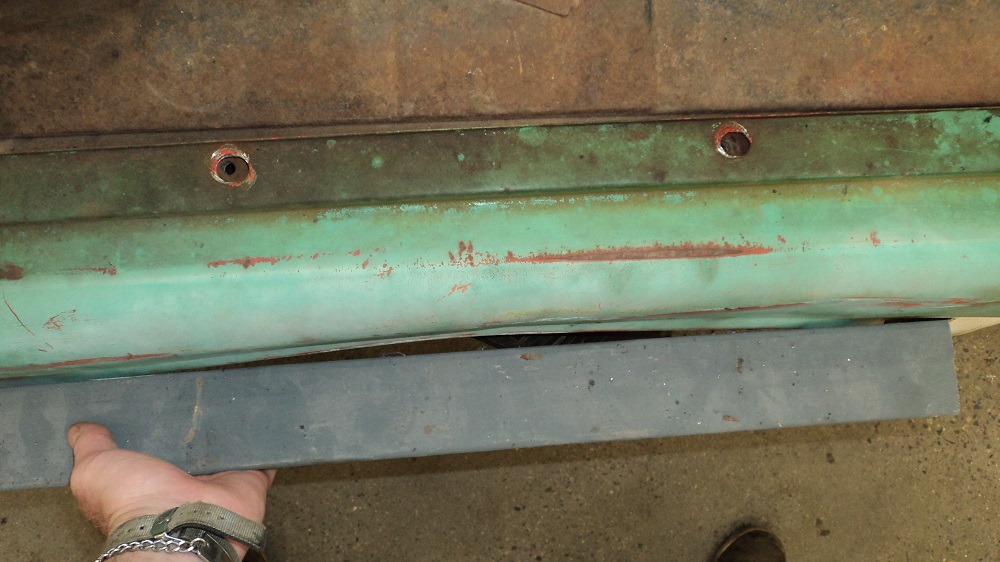
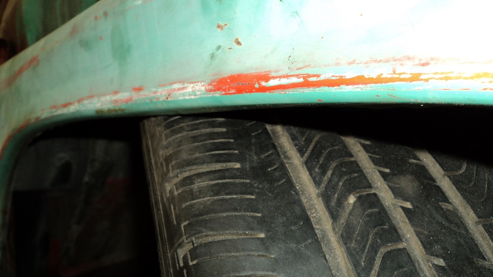
Test fit of the cab on the “finished” chassis. This is ride height (bottom of crossmember 5″ off the ground), and about as low as I can go and still steer.
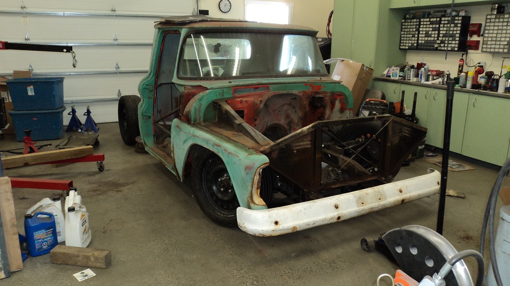
The tire hits the fender, but that fender is actually pushed in, so it might just clear once I fix the fender.
And, assuming I go air ride, this is sitting on the bumpstops (un-trimmed ES9.9101). Control arms are about 1″ off the ground.
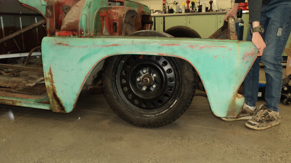
I’m very pleased with how the control arm modifications, spindle adaptations, and Jeep wheels all worked out. Modern rims, modern geometry, good clearance, low ride height, yeah!