[ Titleblock ] [ Tutorial ] [ Get a Property ][ Get a Floor Plan ][ Draw a Floor Plan ][ Elevations ] [ Plot Plan ] [ Kitchen ] [ Model ] [ Section ] [ Paper-Space ]
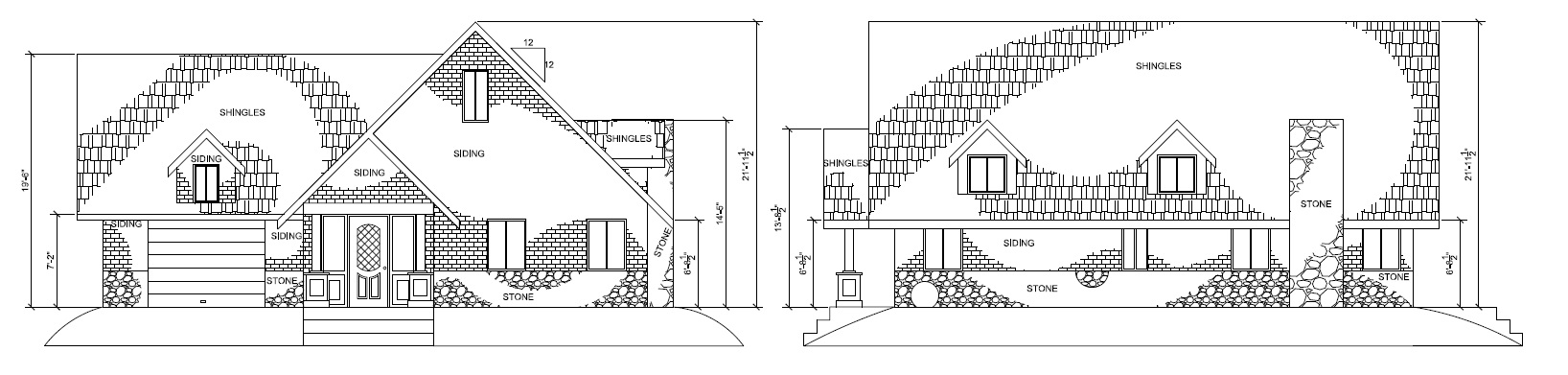
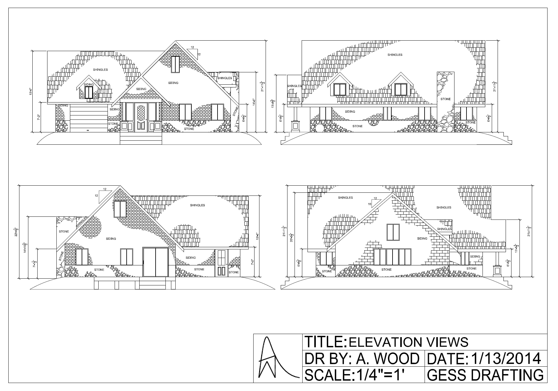
The ELEVATION VIEWS show what the building looks like from all sides
The ELEVATION VIEW:
-
- Tells the siding crew what the outside finish is
- Tells the roofing crew what type of roofing to use
- Tells the roof truss engineers how steep to make the roof (“roof pitch”), and what overhang you want
- Tells the building inspector if the building height meets code
You should already have this file: RIGHT-CLICK and save THIS FILE into your H:\ drive, then insert into your Elevation Drawing just like you did with the floor plan symbols.
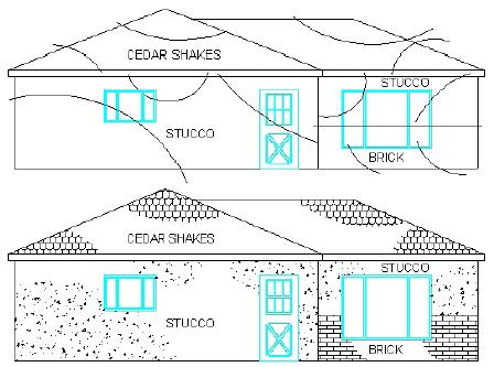
Elevation Drawings are front, back and side views of the house as if you were looking at it. This helps people see what the finished house would look like. Some people cannot visualize from a floor plan.
Image from http://www.exquisitehomesltd.com
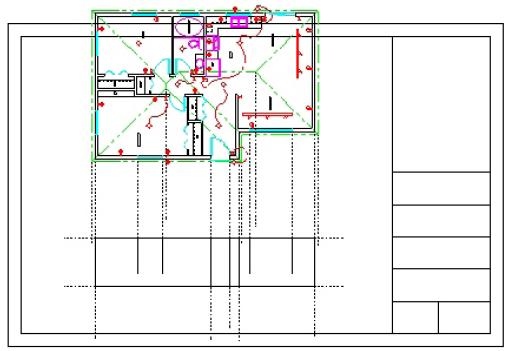
COPY your FLOOR PLAN drawing off to the side, away from your FLOOR PLAN
We will use this copy to do the ELEVATIONS.
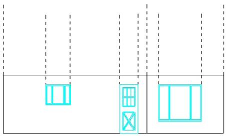
Use your FLOOR PLAN COPY to project lines down and draw your front view
-
- Draw a horizontal line near the bottom (with ORTHO on) for the bottom of the front elevation
- Copy or Offset this line up 8 feet for the ceiling height — this will be erased later on
Trim lines and insert Doors and Windows (from the Symbols file in your H:\ drive)
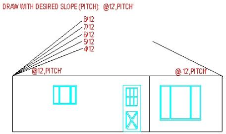
From the 8’ corner draw the slope of the roof with a regular pitch of 4/12, 5/12, 6/12, (Rise/Run) etc.
-
- Draw the slope with a line started at the wall corner and then coordinate entry @12’, 4’ for a 4/12 pitch
- You need to do this like “x,y” to make this work. “Rise:Run” If it goes 12′ in x, and goes 4′ in y, it’s a 4:12 or 4/12 pitch
- A 4/12 pitch is pretty typical in this area of the province
- REMEMBER THE ROOF PITCH YOU CHOSE – it is recorded on the Elevation View
- MAKE IT SOMETHING STANDARD
- MAKE ALL ROOF PITCHES THE SAME
- Look at the examples below:
COPY the line up 6″ for the roof-truss/fascia thickness
EXTEND to the roof peak and overhang
-
- You must match the overhang on your floor plan
- Yes, the FASCIA will sit lower than your CEILING – that is to be expected.
- FASCIA boards are typically 6″ thick.
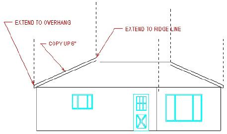
DELETE the 8′ ceiling line you used previously
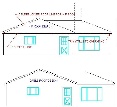
HIP ROOF: keep the 6″ offset line for your fascia; Two horizontal lines 6″ apart become your fascia on the sides – these are where your gutters go. Trim where your walls meet the lower of the fascia lines.
GABLE ROOF: delete the 8′ ceiling line, keep the roof pitch copied line – these are your fascias on the ends. Two horizontal lines 6″ apart become your fascia at the bottom of the sloped roof sides – these are where your gutters go.
DON’T FORGET TO ADD EXTERIOR LIGHTS AND PLUGS!
NOTE: If you are doing multiple stories, you should add 12″ floor joist thickness.
Change to the HATCH Layer and add roofing, siding, stucco, etc..
-
- USE “BHATCH” (Boundary Hatch) and pick appropriate looking hatches for the parts of the house and change the scale to make it look right!!!
- IN PAPER SPACE: LABEL material types (normal names, not hatch names!!!)
- DON’T HATCH THE ENTIRE AREA. Draw curves or splines as shown below, hatch, then erase the lines used
- HATCH EACH VIEW INDIVIDUALLY. Trust me on this. If you don’t, things go wrong when you try to rearrange the views later.
Then draw the remaining sides of the house
DID YOU DRAW A CHIMNEY?
NOTE: The Chimney must extend 3′ above where it pokes through the roof.

COPY and ROTATE your FLOOR PLAN to a new area and repeat with the NEXT VIEW of your house. All the Elevation Views will be placed horizontally
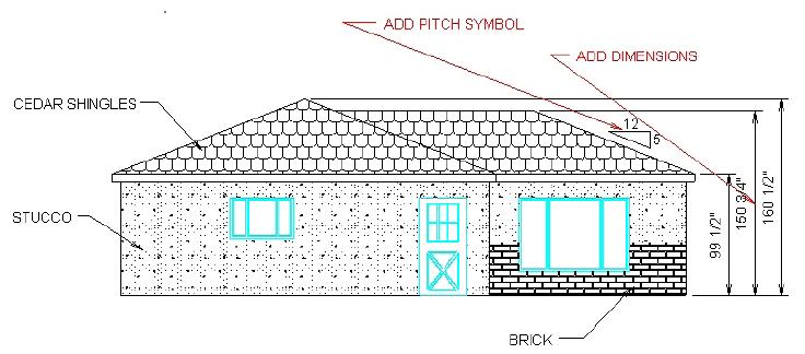
IN PAPER SPACE: Draw a Pitch Symbol – copy the roof line up and draw vertical and horizontal lines then add the numbers of your pitch
IN PAPER SPACE: DIMENSIONS TO ADD:
-
- Ground to each floor IF more than one floor
- Ground to top of the eaves (top of the overhang)
- To all roof peaks
- To top of chimney
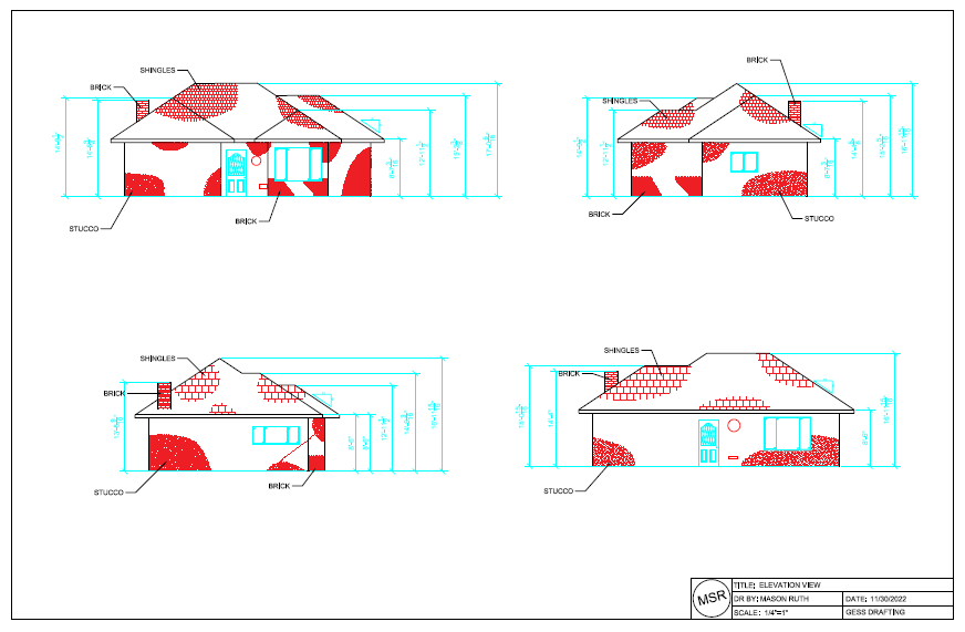
DO NOT do a complete “hatch fill” like you see here – notice it is “visually overwhelming”
IN MODEL SPACE: Arrange all four views into one printable page
IN PAPER SPACE: PDF Printer, ArchD, Insert your title block and scale it to fit
The DRAWING SCALE will likely be 1/8″ = 1′, but whatever comfortably fits the paper.
You may check your drawing on 8-1/2 x 11″ paper, and you will PLOT all your finished drawings at once.
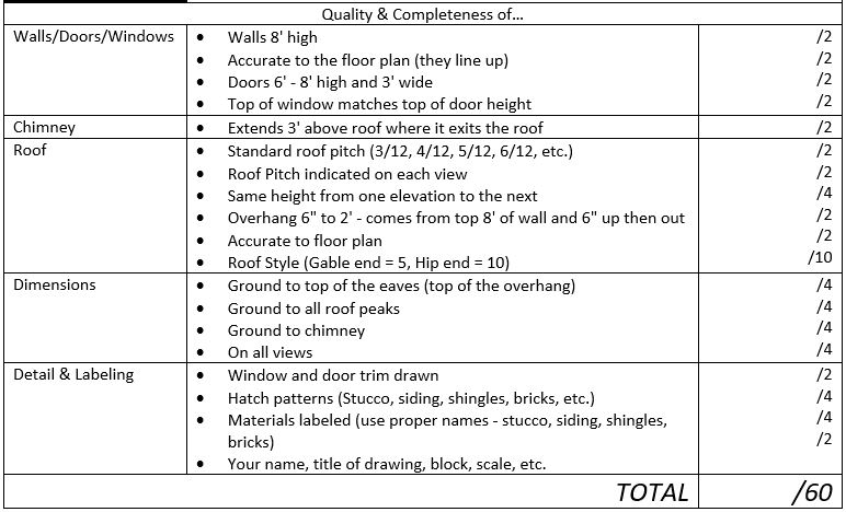
Check off that you have all the REQUIRED CRITERIA completed
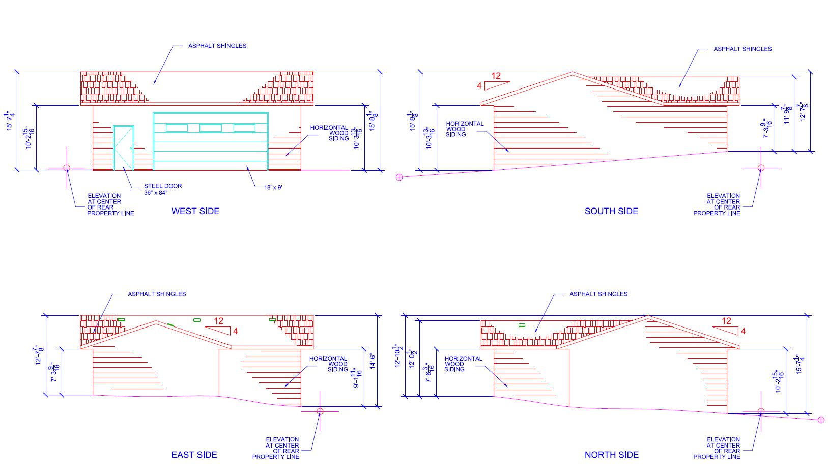
Wellwood’s workshop Elevation, as submitted to the Regional District. There were some changes from this during construction (door windows deleted, windows and vent fan added at top of north side, make-up ducting on east side).
HOW TO PRINT to see about printing a PREVIEW on 8.5 x 11″ (classroom printer) to check for errors. Get me to check!!
HOW TO PRINT to PLOT an ARCH D in (probably) SCALE: 1/4″ = 1′, or 3/16″ = 1′, or 1/8″ = 1′ (whatever fits nicely).
Print out the MARK SHEET and do a self-evaluation before submitting
Next: PLOT PLAN