[ Titleblock ] [ Tutorial ] [ Get a Property ][ Get a Floor Plan ][ Draw a Floor Plan ][ Elevations ] [ Plot Plan ] [ Kitchen ] [ Model ] [ Section ] [ Paper-Space ]
Architectural Drawings are done slightly differently than the drawings we have done so far. We need to set AutoCAD up to draw in the Architectural Style, and make some other settings changes to make our drawing easier.
You will be setting up AutoCAD to do “Architectural”
You will do THIS Tutorial, as well as ALL YOUR HOUSE DRAWINGS in THIS file that you create RIGHT NOW.
OPEN AutoCAD
START a NEW drawing (if you are offered a TEMPLATE, pick “ACAD” ONLY)
SAVE the drawing at “yourlastname-yourfirstinitial-house.dwg”
ie: wellwood-g-house.dwg
HEY CAPTAIN LITERACY! READ THAT “SAVE” INSTRUCTION AGAIN!
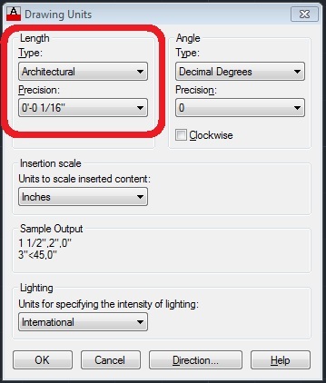
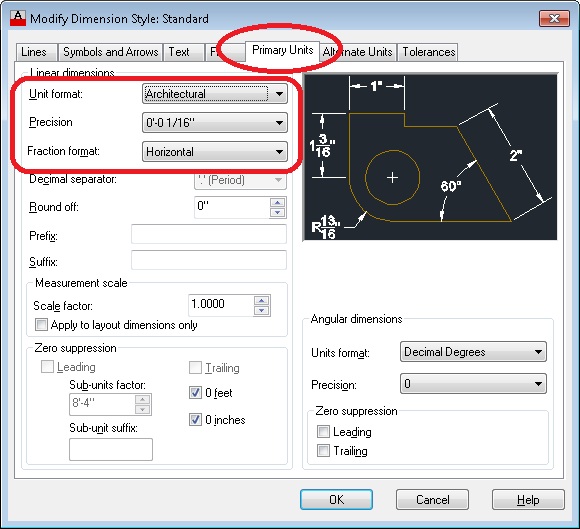
Type UNITS and set the following (DON’T SKIP THIS):
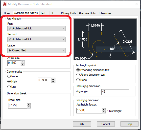
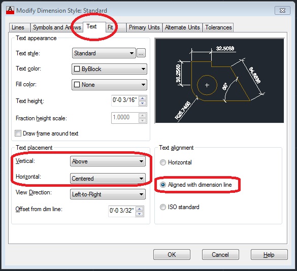
Type D for Dimension Style Manager, click MODIFY and change the following:
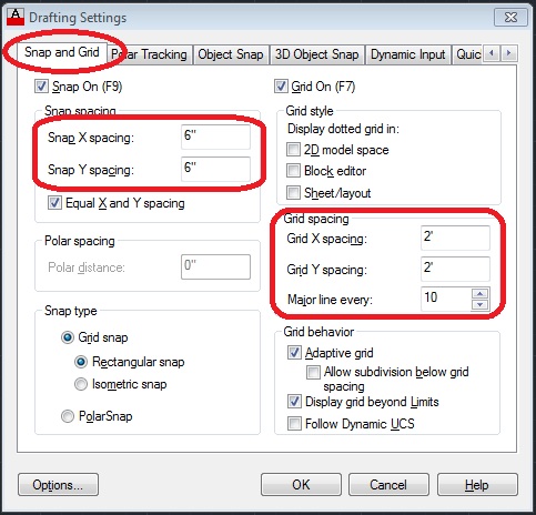
Type DSETTINGS and change the following:
This is going to get odd – you need to wrap your head around this:
MODEL SPACE & PAPER SPACE
There are TWO REALMS OF EXISTENCE in AutoCAD:
MODEL SPACE – The infinite world where you create your drawing, and
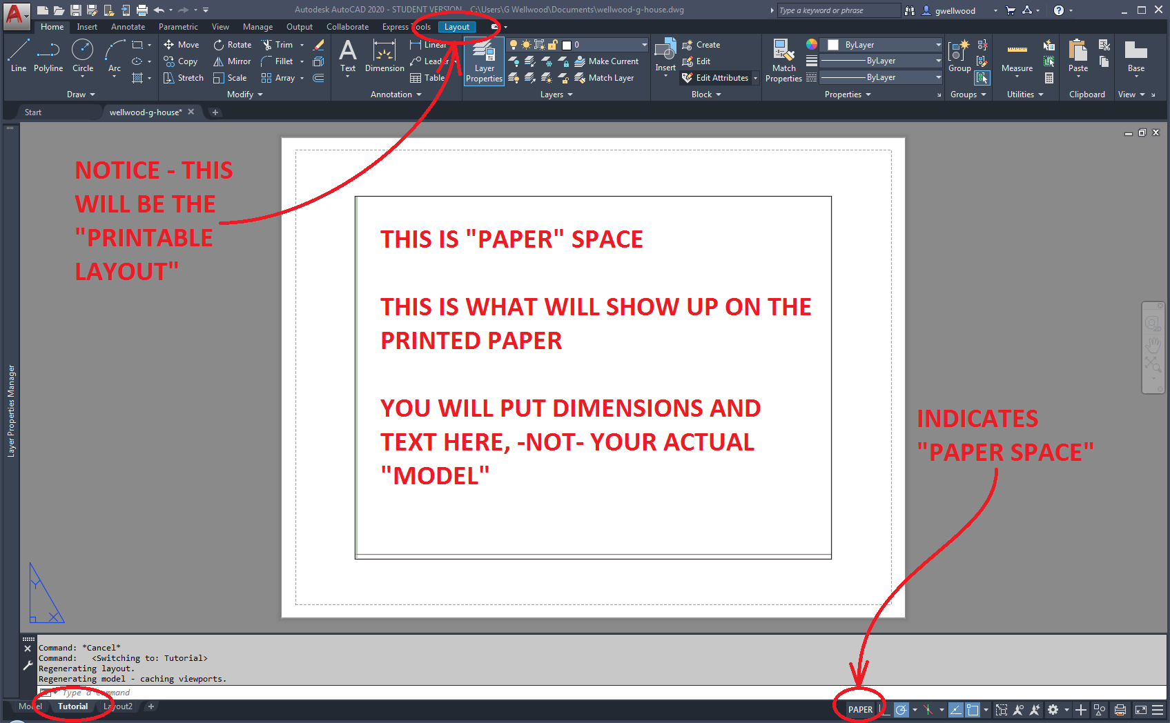
PAPER SPACE – What the printed paper is going to look like. It’s where you insert your titleblock and do ALL your DIMENSIONS and TEXT
We’re going to create the PAPER SPACE:
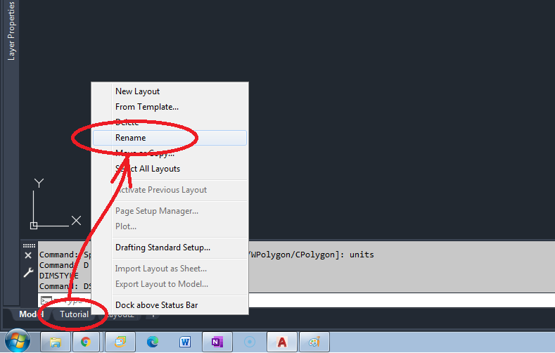
RIGHT-CLICK on the Layout1 Tab down at the bottom, and rename it “TUTORIAL“, then CLICK ON IT to go there. This is a whole new world.
Welcome to PAPER SPACE. You’re looking at the PRINTABLE SHEET OF PAPER:
RIGHT-CLICK on the Tutorial Tab again, and go to PAGE SETUP MANAGER and click MODIFY
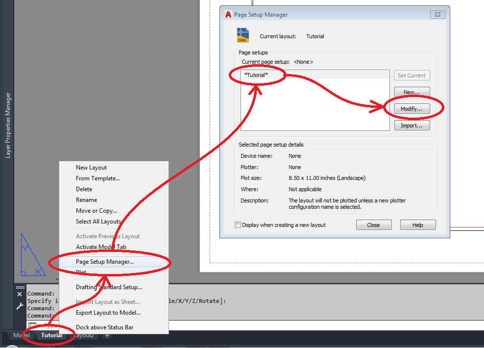
MODIFY:
CHANGE the PRINTER (Pick the Microsoft Printo To PDF app; I use CutePDF at home. AutoCAD does have its own)
CHANGE the PAGE SIZE to ARCH D
CHANGE the PLOT SCALE to 1:1
Click “OK” and then IMMEDIATELY go back into MODIFY again
Click PLOT AREA “What to Plot” and pick WINDOW, and click a box around the ENTIRE WHITE PAGE

STAY IN PAPER SPACE
Go to INSERT your Titleblock (be sure to select Uniform Scale), clicking on the bottom left corner of the page as the INSERTION POINT.
YOU SHOULDN’T HAVE TO, but you CAN – SCALE your Titleblock to fit the page using the bottom left corner as the BASE POINT, and scale it up or down until the right side of the border meets the right side of the page.
NOTE FOR FUTURE YOU: DO NOT SCALE ANYTHING AS YOU DRAW YOUR HOUSE – YOU WILL DRAW IT FULL FREAKING LIFE SIZE IN AutoCAD. IF WE HAD A BIG ENOUGH PRINTER, WE’D PRINT IT FULL SIZE. SCALE NOTHING.

As your AUTOMATIED TITLEBLOCK asks for inputs, the DRAWING SCALE will be 1/4″ = 1′ for most of your drawings in Architecture.
![]()
You should now have a LARGE piece of white paper on your screen, with a small rectangle of what USED TO BE your printable page size.
Click that small VIEWPORT BORDER (that box in the lower corner of your page, currently 11×8.5″, shown below in RED) and DRAG it to fit to the extents of your PAPER SPACE so the VIEWPORT BORDER is the SAME SIZE as the larger white paper on your screen. the VIEWPORT BORDER is the WINDOW through the PAPER into the infinite black screen world of your drawings – you want it to fill the page.
![]()
Type LA and confirm that the LAYERS made it into your drawing when you imported your Titleblock.
LEFT-CLICK once on your Titleblock so that it is highlighted (you should see it highlighted in blue). Go to the LAYER Drop Down on the RIBBON MENU and select the BORDER layer. This should put the border on the border layer, and it will automatically pick up the Border Layer attributes (colour, linetype, etc)..
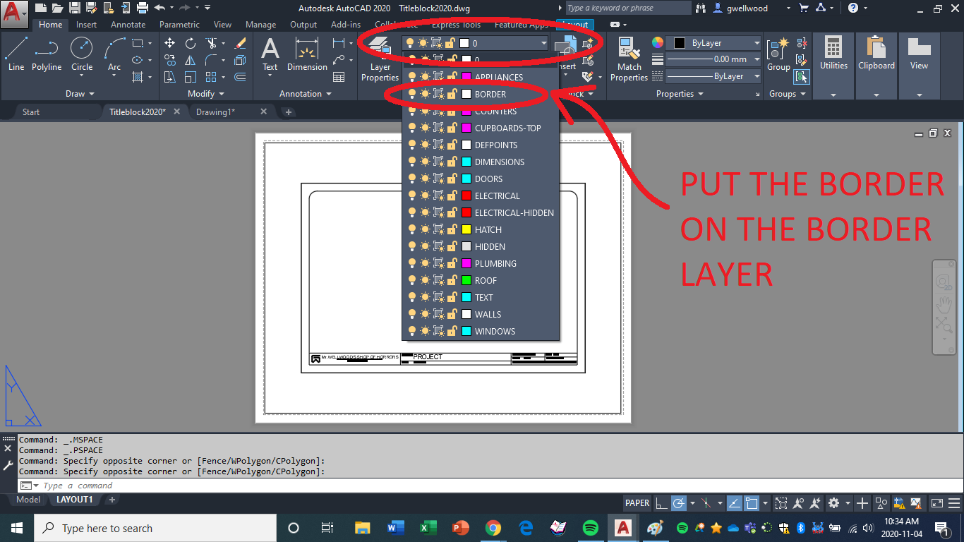
Hit ESC on your keyboard to un-select the border.
NOW is a good time to SAVE
AutoCAD will crash often, flushing everything you did away. Save often.
The quick command for save is [CTRL]-[S] on your keyboard
If in doubt, save it out!
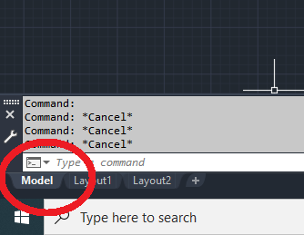
We will leave PAPER SPACE for now. Go back to the MODEL TAB where we started a while ago.
Go to the LAYER drop down on the Ribbon Menu again, and select the WALLS layer. This makes the WALLS layer active. Everything you draw now, will be on the WALLS layer.
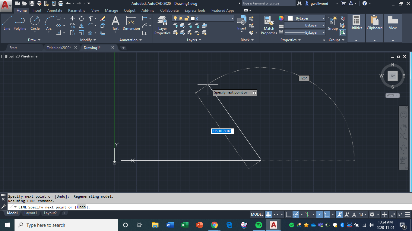
Type LINE (or even just L) on your keyboard and hit ENTER OR hit SPACE (they mean the same thing). Click somewhere close to the origin (x,y) of your screen to start a LINE. INSTEAD of clicking the next point, I want you next to type 33′<0 and hit ENTER or SPACE.
This will draw a line 33 feet long, exactly horizontal to the left, like X=0 on a graph in math.
It may not fit on your screen, since your screen is showing only 12″ of earth, and we drew a line thirty-three times longer.
INCHES AND FEET:
A single quote ( ‘ ) means FEET. A double quote ( ” ) means INCHES. If you do not specify, AutoCAD will do INCHES by default. That could be a very small house.
You should have something like this:
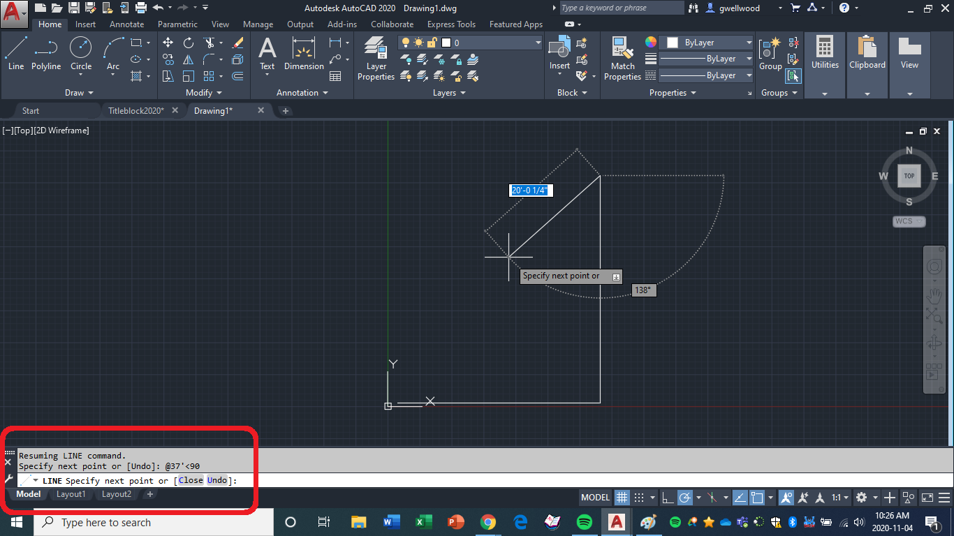
Assuming you are still in the line command, now type 37′<90 and hit SPACE (I use space instead of ENTER – it’s easier for me; it means the same thing in AutoCAD). This will draw a line 37′ straight up.
Angles start at horizontal to the right at 0°, and go COUNTER-CLOCKWISE through graphing quadrant I then II then III then IV.
You should have something like this:
If you somehow got out of the LINE command, just type LINE again, then type END (tells AutoCAD you want to grab the ENDPOINT) and click on the end of the line you previously drew. This will ATTACH to the END of a line (you can also use MID, PERP, TAN, QUAD, etc, depending on what and how you want to attach).
Now let’s complete the shape with these commands: 20′<180 [SPACE] 12′<270 [SPACE] 13′<180 [SPACE] c (for close). You should now have this:
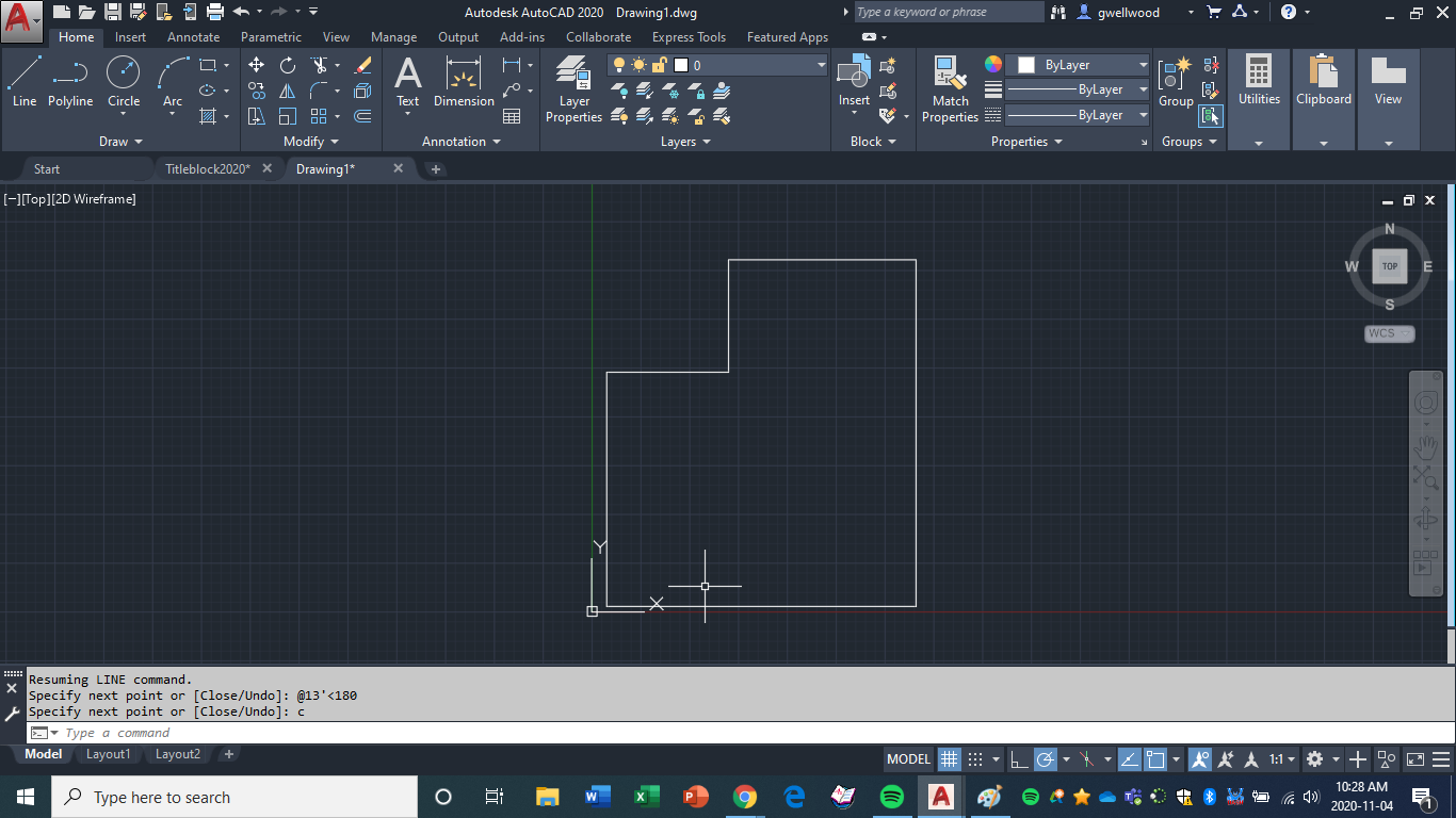
This is the outside perimeter of my workshop at home. Let’s add some wall thickness. Type OFFSET and hit [SPACE]. The first question it’s going to ask you, is “how much?” Offset copies a line/object/circle/whatever a set distance.
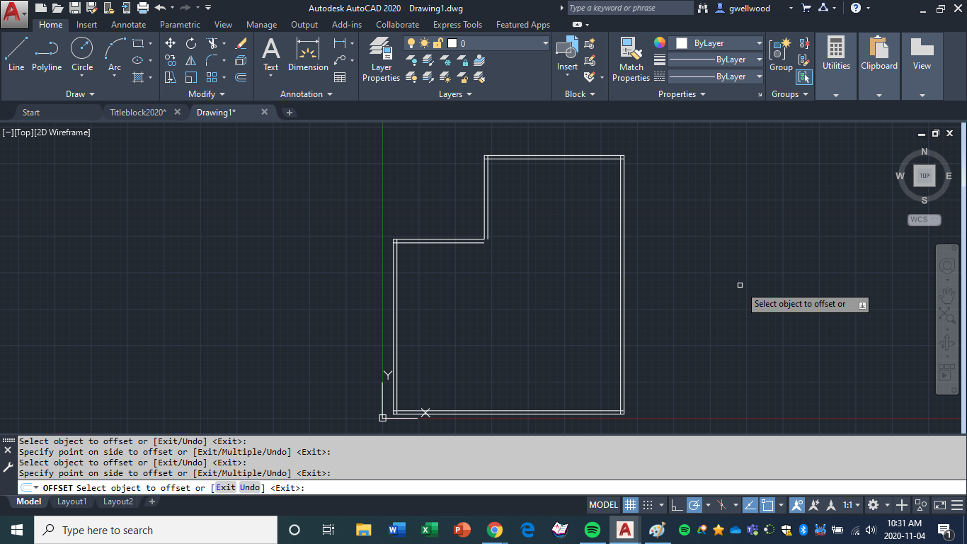
Type 6″ [SPACE] to offset these walls 6″ inside. Click on a line, and then put your cursor inside the shape we drew – you should see the potential new line show up ready to go. Click on the inside if it’s working, and you should have a thicker wall.
You can scroll the mouse wheel to zoom in or out
You can double-click the mouse wheel to zoom everything and re-center your view
You should now have this (hit [ESC] to exit the command):
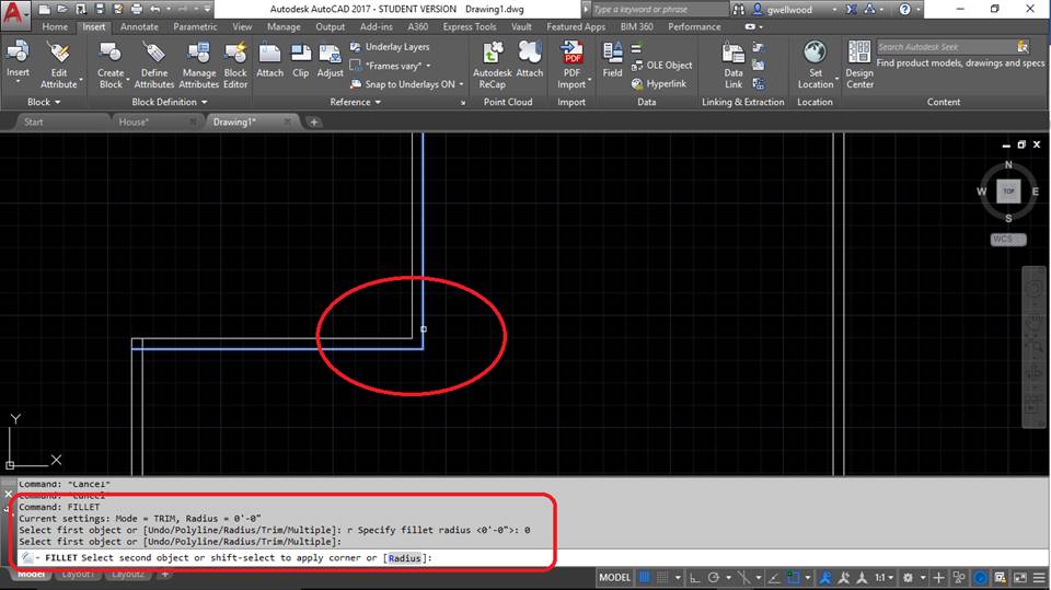
Notice that some of the lines overlap, and some of the lines don’t even touch. Type FILLET (pronounced Fill-It. Fill-ay is for fish) on your keyboard, and hit [SPACE]. Type R to change the RADIUS of the FILLET (Fill-It, not Fill-ay – these are not fish) and make the RADIUS 0, hit [SPACE], then click the two lines on the top left that are not touching. This should extend them to each other perfectly, like this:
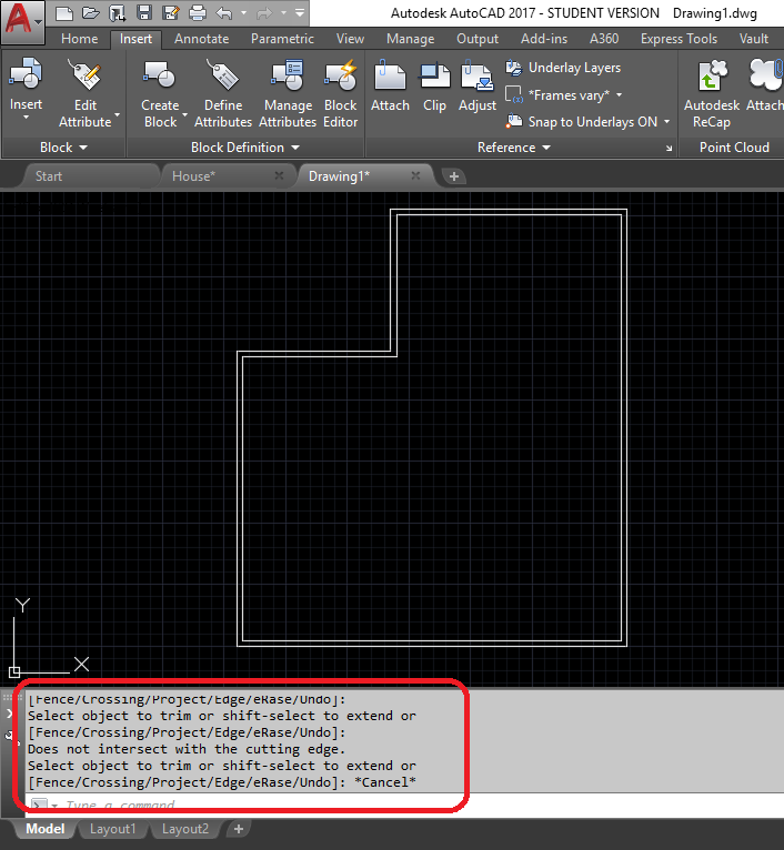
Next, we’re going to trim off the other lines. Type TRIM (or just TR) and hit [SPACE]. Trim now gives you some options. Look at what is saying on the screen to you : the first option it is asking you is “What do you want to trim TO?” You can click a line, or click a bunch of lines, and hit [SPACE], then click the sections you want GONE. Alternatively, instead of clicking lines to trim to, just hit [SPACE] again, and ALL lines become lines you can trim to. Clean up the shape to look like this:
NOTE: You can often END a command by hitting [SPACE] when done. You can re-start that command again by just hitting [SPACE] again, and AutoCAD will bring it right back up again. This can save time when doing lots of the same thing.
You are now going to learn some more commands in AutoCAD.
CIRCLE
You don’t often need to draw circles in a house design, but you can. There are a variety of ways to choose a circle:
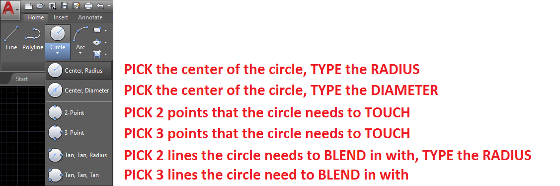
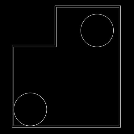
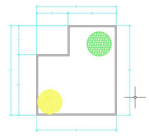
Draw a “Center, Radius” circle in the top right of your shape, and a “Tan, Tan, Radius” circle (notice how it attaches to the walls) in the bottom left, both with a Radius of 5′, as shown:
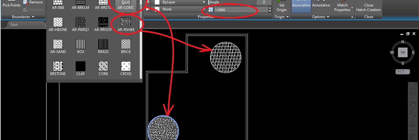
HATCH
This allows you to “FILL” a shape. In Architecture, there are specific patterns that represent their material. It matters.
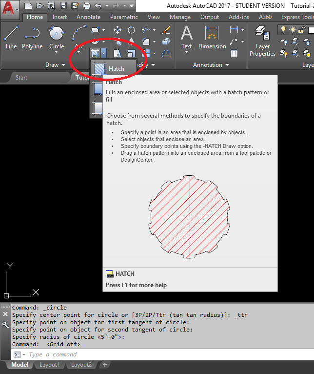
Click on HATCH and fill the top right circle with AR-SHAKE (roofing), and the bottom left circle with AR-CONCRETE. Make sure the SCALE is set to 1.000

Have you saved recently? Just asking….
Now, SWITCH back to PAPER SPACE. Paper Space is the “Paper Reality.”
If you don’t see your drawing, SWITCH to MODEL SPACE, and double-click the wheel of the mouse to re-center your view. Your drawing should arrive and fill the page (those dotted lines are coming – don’t you worry about those yet!).
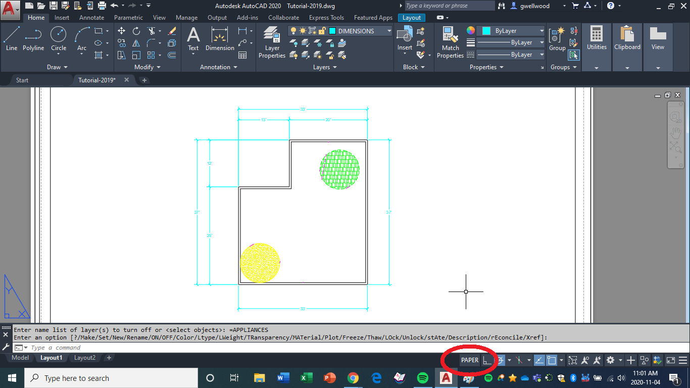
Don’t worry about the hatch colour change – that’s coming up…
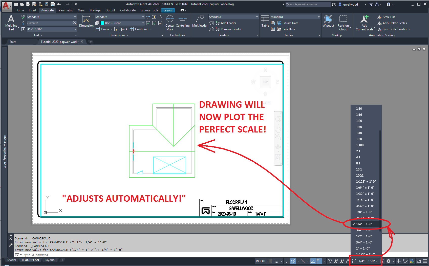
Remember how I asked you to set the SCALE of your drawing in your TITLEBLOCK to 1/4″=1′? In Drafting, the actual size of the drawing on the page is CRITICAL. It MUST be a SPECIFIC SCALE, so if someone had to, they could just measure off your drawing and do math to find out how big it should be.
Thankfully, AutoCAD can help us with that.
In MODEL SPACE, click the SCALE thing at the bottom of the screen, and pick 1/4″=1′. If we’re lucky, everything will fit the screen (we could always pick a different scale if we had to).
Positive Brownie Points if you noticed that the drawing above had changed. Good catch!
Negative Brownie Points if you just went back to look again.
SWITCH INTO PAPER SPACE.
All your DIMENSIONS, TEXT and NOTES are to be done in PAPER SPACE.
READ THAT LAST SENTENCE AGAIN
All your DIMENSIONS, TEXT and NOTES are to be done in PAPER SPACE (Deja-Vu)
ONE MORE TIME
TEXT (SINGLE LINE)
I find TEXT (SINGLE LINE) is less problematic than MULTILINE. I usually just throw down all the text, and then move each text to where it needs to be. You used this to create your TITLEBLOCK.
DIMENSIONS
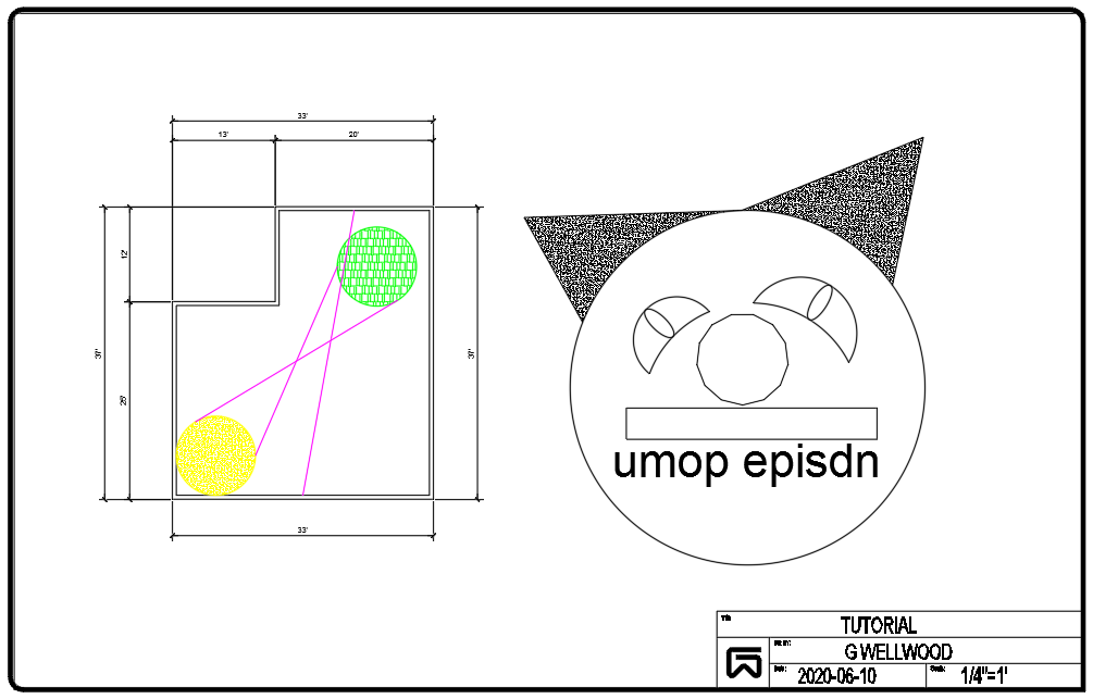
We will likely use LINEAR the most in Architecture. Dimension your shape exactly as shown below. Notice the “notches” in the structure are on the inside, and the “overall” dimensions are on the outside.
While the SUNSHINE dimensions usually worked well in Fusion360, I find they often DON’T do what I want here. Avoid them.
Unlike all other dimensioning, in Architecture we dimension EVERYTHING. There may be ONE crew doing EACH wall, you don’t want to make them have to do math.
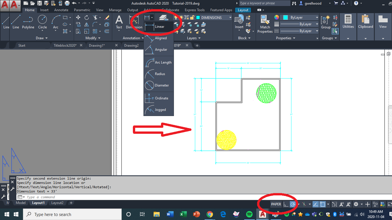
NOTICE how I’m arranging the dimensions. ALL the surfaces are there.
NOTICE what corners I am connecting to.
NOTICE the extension lines do not touch the object. NOTICE the overall dimension is the outermost dimension.
NOTICE the arrowed lines line up.
NOTICE the person beside you who didn’t do this. Point this sentence out to them and laugh at them.
SHOW me that you actually read this for an extra bonus mark.
LAYERS
Layers GREATLY help both organization AND speed. Since layers are set up with specific colors and linetypes, we can quickly and easily change the lines to be what we need by putting them on an appropriate layer.
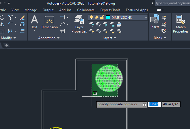
SWITCH TO MODEL SPACE
Click and drag a crossing-box over the TOP-RIGHT circle and hatch, then select ROOFING layer from the DROP-DOWN on the Ribbon Menu.

Put the BOTTOM-LEFT circle and hatch on the HATCH layer
Put the WALLS on the WALLS layer
IN PAPER SPACE, put the DIMENSIONS on the DIMENSIONS Layer
WHAT CAN I DO TO DRAW FASTER, AND MORE ACCURATELY?
OSNAP!
OSNAP
“OBJECT-SNAP” allows you to grab different parts of things. This helps immeasurably in speed and accuracy.
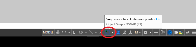
You can turn it ON and OFF with this icon at the bottom:
Click the white triangle arrow thing, and see what the options are:
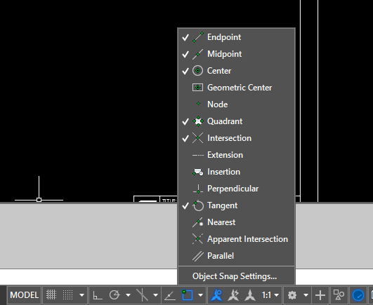
The ones checked are the ones I typically use. I’ll check the others only when I need them.
NOTE!! Sometimes TOO MANY OSNAPS ON make AutoCAD not know what to grab.
NOTE!! OSNAP and regular SNAP don’t get along; they fight each other!
I only use SNAP for TWO THINGS:
-
-
- Drawing walls at 2′ increments in MODELSPACE
- Locating dimension lines in 1/4″ increments in PAPERSPACE
-
I use OSNAP almost all the time – for almost everything!
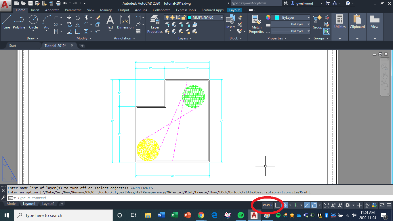
Use a MIDPOINT OSNAP to draw a line from the middle of the lower horizontal line to the middle of the upper horizontal line.
Use a QUADRANT OSNAP to draw a line from the right side of the LOWER-LEFT Circle to the left side of the UPPER-RIGHT circle.
Use a TANGENT OSNAP to draw a line between the two circles (you likely will need to turn off CENTER and QUADRANT to make this work)
PUT all three lines on the CUPBOARDS-TOP layer. They might not look like a dotted line in MODEL SPACE – but they should in PAPER SPACE – have a look to make sure!.
IN MODEL SPACE, Using the various draw commands, make a quick drawing of how you’re feeling right now.
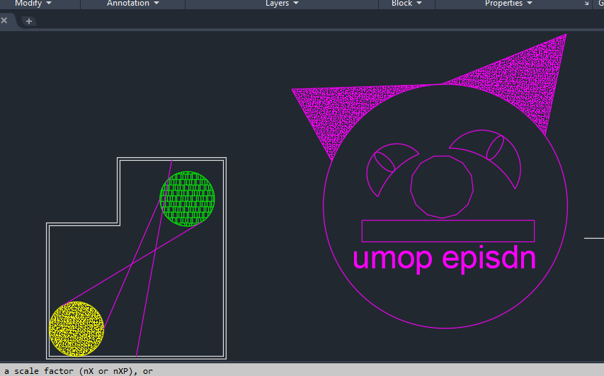
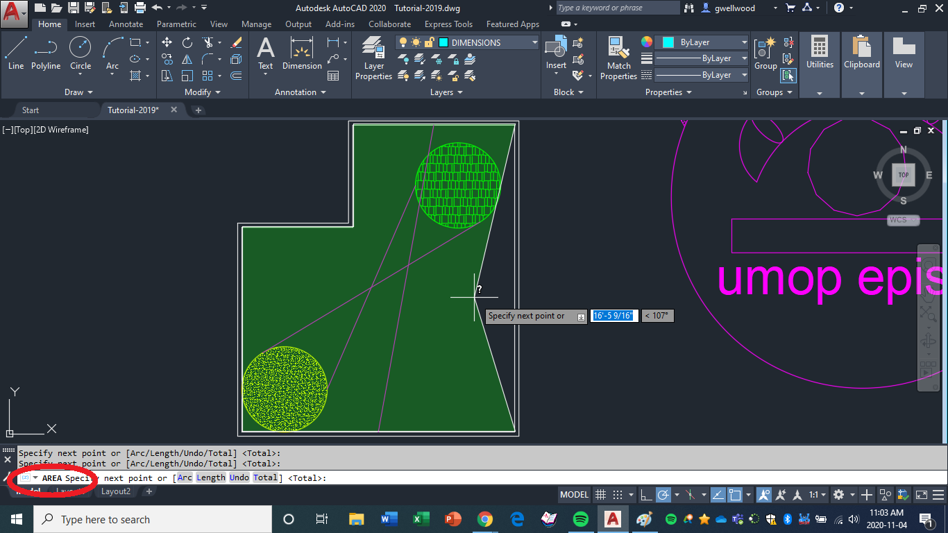
Type AREA, then click the outer corners of your structure – AutoCAD automatically calculates the area (in square feet) for you.
Use TEXT – SINGLE LINE to add the AREA as well as the PERIMETER to your drawing.
Show your work to your Instructor for marks, and get your property!
SWITCH back to the MODEL TAB to continue.
DON’T DELETE NOTHIN’!
Hold the Mouse-Wheel down to PAN the view off the screen for a fresh workspace for your house – this keeps ALL the settings you’ve already SET.
I’m totally going to make fun of you if you don’t do this. “How come my lines don’t work?”
Next: GET A PROPERTY