
[ Titleblock ] [ Tutorial ] [ Get a Property ][ Get a Floor Plan ][ Draw a Floor Plan ][ Elevations ] [ Plot Plan ] [ Kitchen ] [ Model ] [ Section ] [ Paper-Space ]
GO BACK AND SETUP AUTOCAD, IF YOU DIDN’T ~ACTUALLY~ DO IT
The FLOOR PLAN DOES NOT INCLUDE ANY “PROPERTY” DETAILS
The FLOOR PLAN:
-
- Tells the concrete crew where to pour the foundation
- Tells the framing crew where to build the walls
- Tells the door and window crew what size doors and windows to use, and where they go
- Tells the plumbing crew where to put sinks and tubs and such
- Tells the electrical crew where to put the outlets, lights and switches
- Tells the roof truss engineers how big the building is so they can design your roof trusses
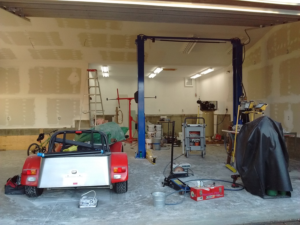
NOTE: Your concrete forming crew will LOVE YOU if all your walls are of 2′ increments. Concrete forms come in 2′ sections.

Wellwood’s workshop concrete forms – they come in 2′ increments.
He, unfortunately, had to cut a number of 1′ increments (sadness).
Draw the PERIMETER of your house FIRST
DRAWN IN MODEL SPACE
(Recommend 2′ increments – ie: 10′, 12′ or 22′, not 33′ or 10′-3-3/8″)
It is easy to draw the outside perimeter first, then give the walls thickness.
- Change to the WALLS Layer
- Use LINE to Draw the outside of the walls using coordinate entry
- You are drawing the outside perimeter right now
- Draw the wall lengths in 2′ increments (38′ is good, 37′ is bad, 38’3-5/16″ is way out)
- MAKE SURE YOU DRAW IN FEET not INCHES (12′ not 12″)
We will be drawing FULL SIZE (Don’t scale nuthin’!) – if we had a printer big enough, we would print out a FULL SIZE house, and ACTUALLY walk around on it
- Click on ONE of your lines
- Select [MODIFY] from the Drop-Down menu
- Chose [EDIT POLYLINE] (AutoCAD will say that it is not a polyline, and ask if you want to convert it into one)
- Type [Y] and hit enter (it will then give you an opportunity to JOIN more lines)

- Type [J] to join more lines (and automatically turn them into polylines)
- Select all the other lines (AutoCAD will convert them automatically)
- This will make your wall segments all one POLYLINE instead of separate lines
- Converting to POLYLINES makes it much easier create the wall thicknesses
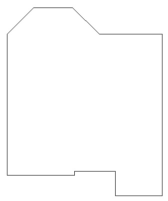
Perimeter drawn, converted to POLYLINES, and JOINED together.
- Use OFFSET to offset the outside wall line inside 6″
- Outside walls are 6″ thick, because there is insulation in them
- Select all and use EXPLODE to turn the lines back to regular lines
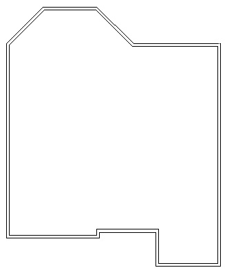
Perimeter OFFSET inside 6″ (for exterior walls).
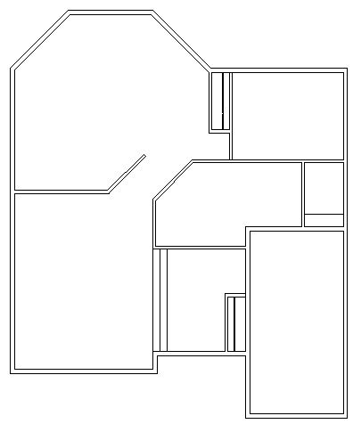
Interior walls will be dimensioned by their CENTERS to the outside of EXTERIOR walls.
Offset the edge of an outside wall to where you want the interior wall to be.
NOTE: Your framing crew will LOVE YOU if all your walls are located at even foot or half-foot (6″) increments.
NOTE: Your drywalling crew will LOVE YOU if all your walls are of 8′, 10′, 12′, or 16′ increments, since drywall comes in these lengths. Having walls in these lengths (or less) saves mudding and taping vertical edges.
Lots of vertical drywall edges – my short truck can’t carry long panels – I got real good at drywall
REMEMBER THAT “HIDDEN” LAYER WITH COLOUR “255” ??? WE’LL USE IT NOW!
- Use OFFSET or COPY to copy the outside lines into position for interior walls, then OFFSET them 2″ on both sides to create 4″ thick walls
- Inside walls are 4″ thick, because they are not insulated
- CHANGE the interior wall centrelines to HIDDEN Layer using Properties
- We use the wall centers for dimensioning later! DON’T skip this – I’ll laugh at you later.
DRAWING DOORS & WINDOWS
DRAWN IN MODEL SPACE
YOU NEED SYMBOLS
RIGHT-CLICK and save
>>THIS FILE<<
into your Documents Folder
IT HAS DOOR & WINDOW & FURNITURE & PLUMBING SYMBOLS!
DOWNLOAD >>THIS FILE<< FOR EVEN MORE
(albeit kind of disorganized, & you must EXTRACT it)
- Change to the WINDOWS or DOORS Layer
- Use [INSERT BLOCK] in the [INSERT] menu to insert Doors and Windows from the Symbols file you just saved. (These symbols are Full Size, do not scale them. Your house is drawn Full Size, do not scale it either)
- If you cannot find the item symbol you want, just draw a simple version of it, and label it as to what it is.
- NOTE: Outside doors and windows MUST be accurately located as we will dimension to them
- NOTE: Outside doors are 36″ wide
- NOTE: Doors open INTO the building/room
- NOTE: Doors MUST have a 4″ wide jamb on either side
- NOTE: Your house MUST have TWO exits.
- NOTE: Sliding patio doors are 60″, 72″ or 84″ wide
- NOTE: Exterior Doors are bigger, and have a Sill Plate
- INSERT doors to the end of the appropriate wall and then MOVE them using coordinate entry (minimum 4″ away from the wall – this is the door jamb – it is important)
- NOTE: Inside doors are NOT dimensioned to. Place them where they look best.
- NOTE: Doors usually open against an adjacent wall – DO NOT have them in the middle of a wall.
- NOTE: Inside doors are typically 30″ wide
- NOTE: Windows typically come in 1′ wide increments
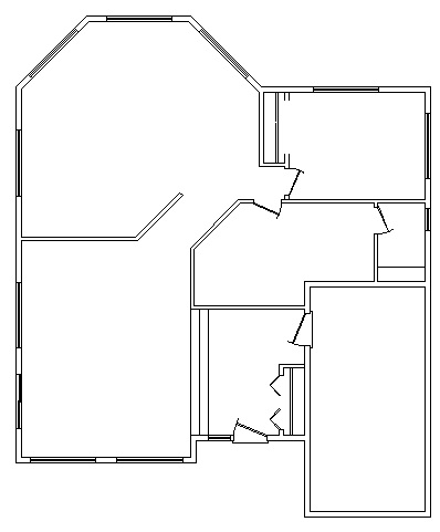
Doors and windows placed, walls trimmed.
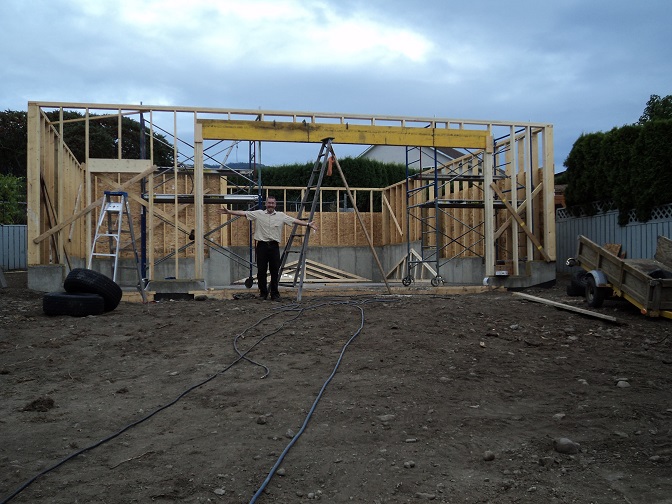
Wellwood frames his workshop – note the BIG lintel above the doors to spread the load of the roof over the opening
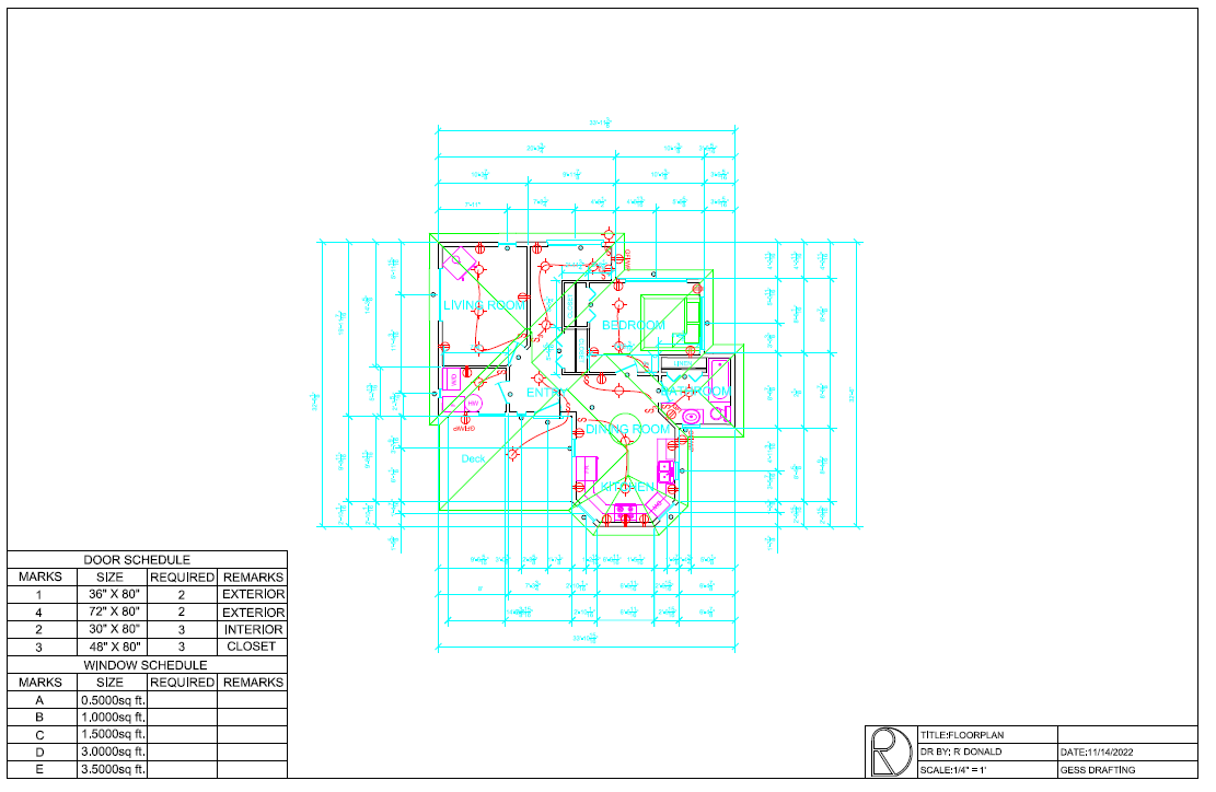
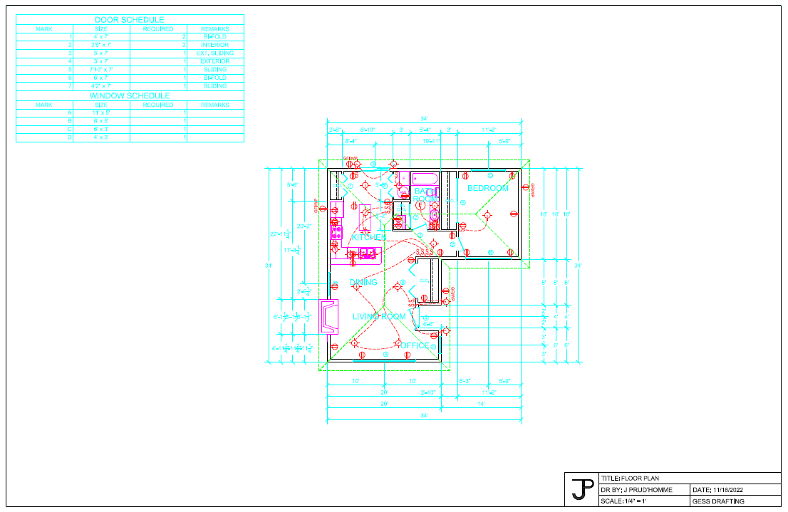
WINDOW & DOOR SCHEDULE
DRAWN IN PAPER SPACE
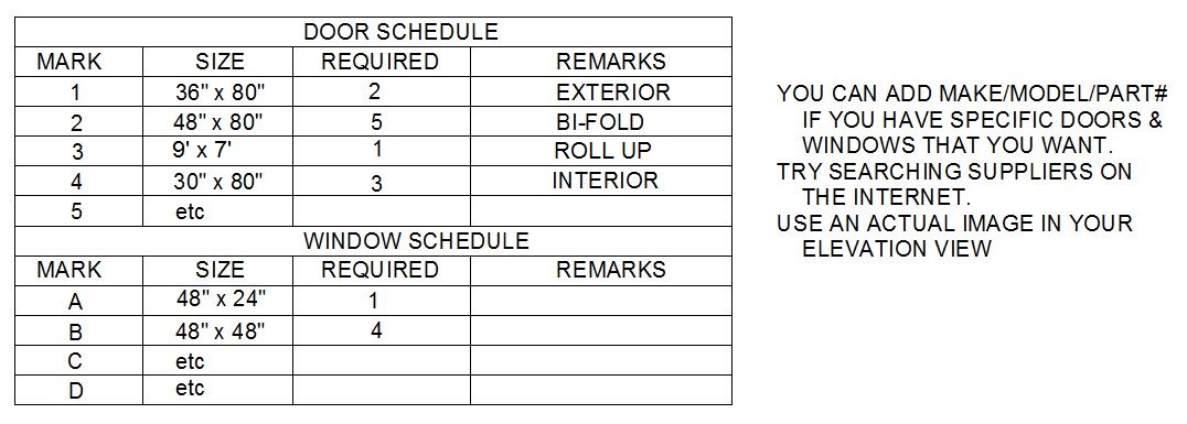
Labeling specific details about the doors and windows will make the floor plan cluttered. Instead, we make a Window & Door Schedule:
-
- AutoCAD can do tables, but I find it faster to just draw one using lines.
- Label common sized doors by NUMBER, and windows by LETTER. You may need to think about how tall the windows are going to be. They are usually in 1′ increments.
- Create a table near your house as shown below for the Window and Door Schedule.
- The Window & Door Schedule will printed as part of the floor plan drawing.
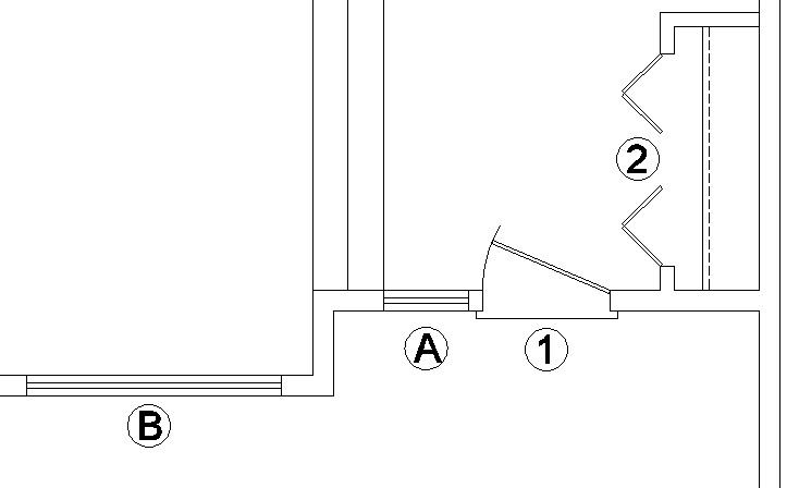
Doors use numbers, windows use letters
CLOSETS
- COPY the back wall of the closets forward 16″ for a shelf, then COPY this line back 2″ for the rod.
- Closets are 2′ deep
- Shelves are 16″ deep
- Rods are 2″ behind the shelf
- Clothes and Coat closets should be around 2′ deep, (inside-to-inside).
- You need a Coat closet near the main entrance, minimum 6 square feet (ie: 2′ x 3′ = 6ft2).
- Every bedroom must have a closet, minimum 6 square feet.
- Linen closets should be in or near the main washroom, and are 20″ deep (inside-to-inside). Broom closets are also 20″ deep.
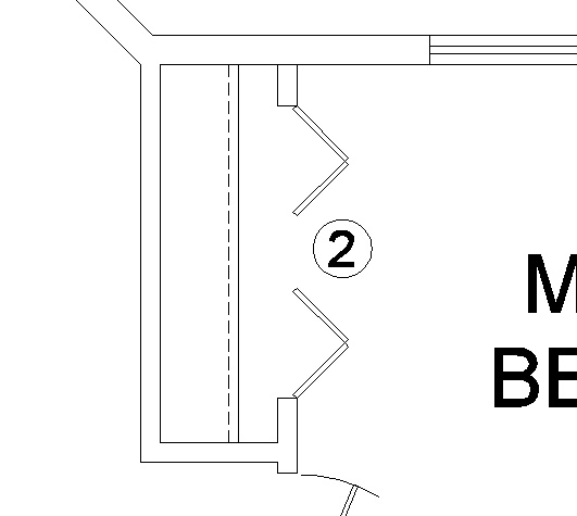
2′ closet, 16″ shelf, 2″ rod
COUNTERS/PLUMBING/APPLIANCES
- Change to the appropriate layer
- OFFSET the Kitchen walls in 24″ for counters and TRIM to size
- OFFSET the Kitchen walls in 12″ for Top Cupboards and TRIM to size – CHANGE to CUPBOARDS-TOP Layer
- OFFSET Bathroom walls 18″ or 20″ for counters and TRIM to size
- INSERT the utilities into the proper location
- You REALLY want a window in front of the sink
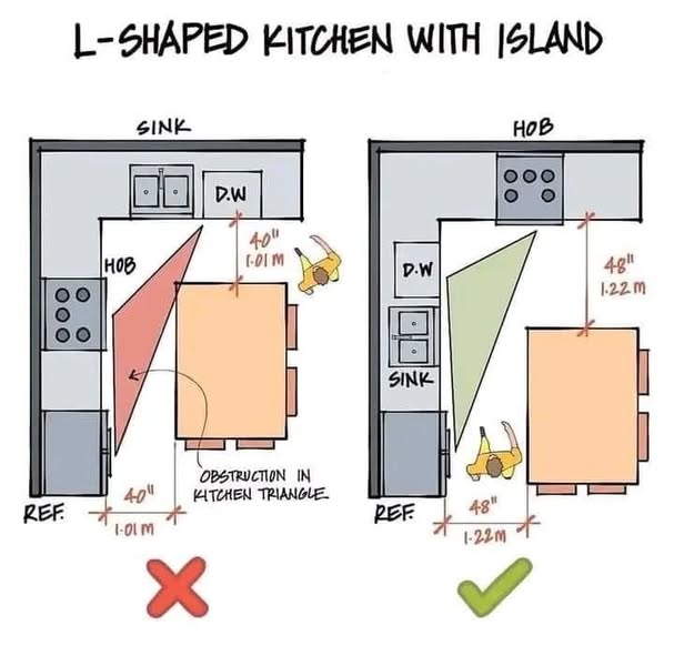
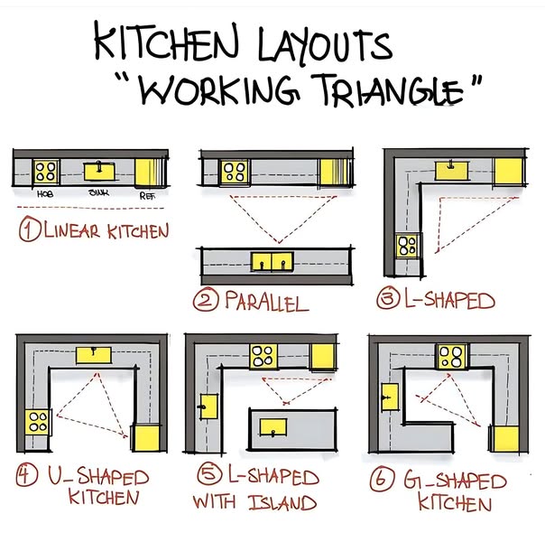
- GOOD Kitchen designs have a “Triangle” of work space: the SINK and the STOVE and the FRIDGE are a triangle of operation. Try to do that.
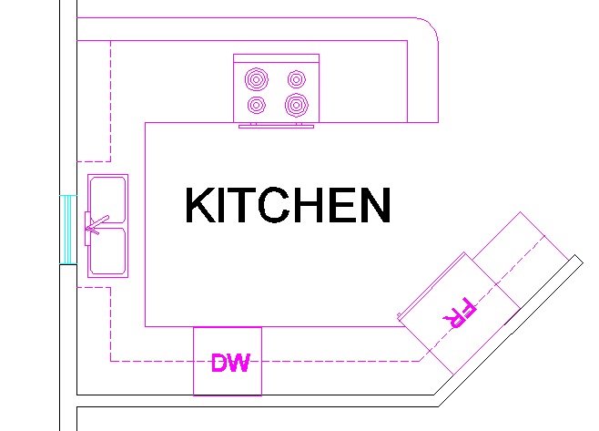
Counters, sinks, & appliances
FIREPLACE
- You must have a Fireplace in this house. Rules. I know.
- You can pick an existing design from the Symbols File, or you can design your own. It can be gas, or traditional wood (you may NOT choose electric).
- A Fireplace is usually a central focus item in a family room or living room.
- REMEMBER: You will have to draw the chimney in the Elevation Views later on.
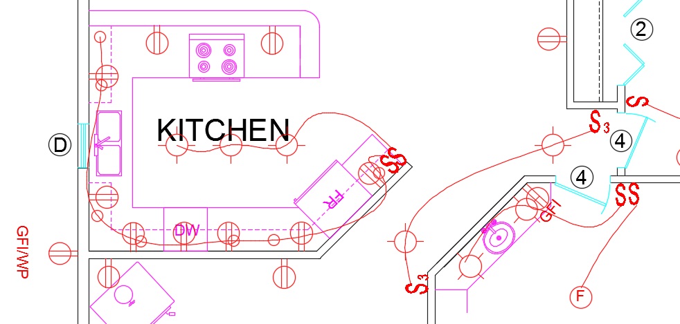
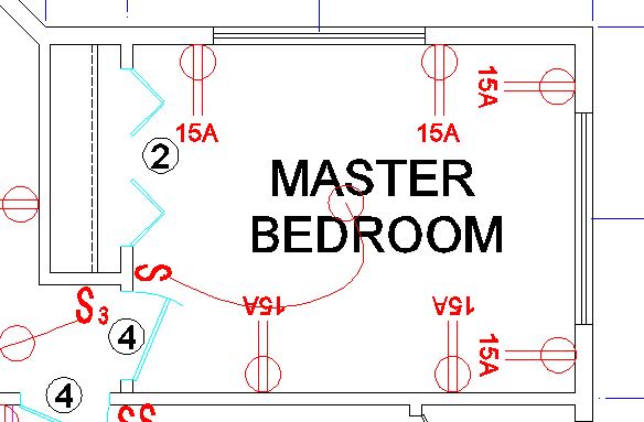
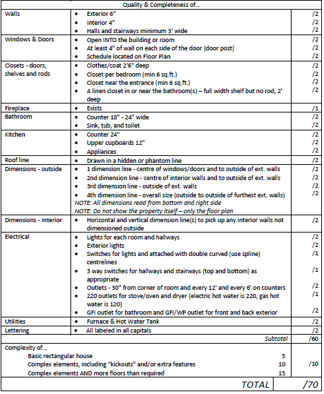
ELECTRICAL
- CHANGE to the ELECTRICAL Layer
- Insert lights, plugins, switches
- WIRE THE LIGHTS TO THE SWITCHES
- CHANGE to the ELECT-HID Layer and using SPLINE, draw an S-curve to connect the switches to the appropriate lights – double right-click to end the curve command.
- Switches need to be by the open side of the door
- DO NOT WIRE THE WALL SOCKETS
- Outlets need to be about 30″ from the corner of each room, and another every 12′ (every 6′ on counters)
- I “eyeball” it – truthfully, the outlets will go where a wall stud is.
- Bathrooms need a GFI outlet (Ground-Fault-Interrupter)
- Outside needs at least two GFI/WP (Water-Proof) outlets – one each on opposite sides of the house
- You need outlets for all your major appliances:
- 240V/40A = Range (oven)
- 240V/30A = Clothes Drier, electric hot water tank
- 120V/15A = Gas hot water
- 120V/15A = Washer, Fridge, Dishwasher
- 120V/20A = Current trend in kitchen outlets (no pun intended)
- You need THREE-WAY-SWITCHES in a hallway (among other places), where two switches control one light (S3)
- You need exterior lighting at each exterior door (switched inside), and lighting over patio areas.
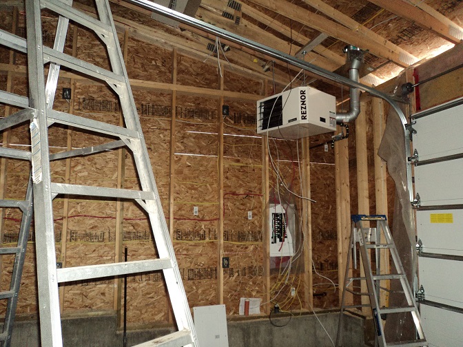
Wellwood wires his workshop (he -really- enjoyed wiring!)
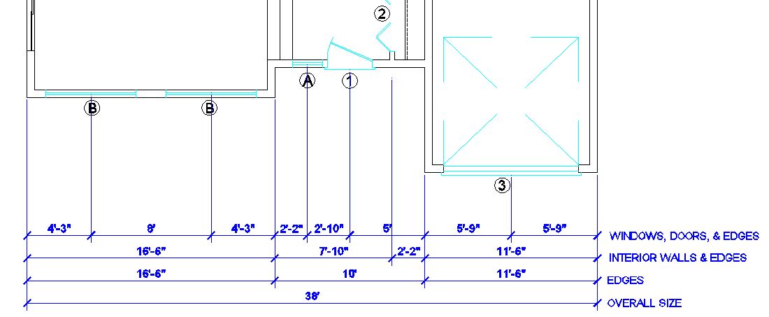
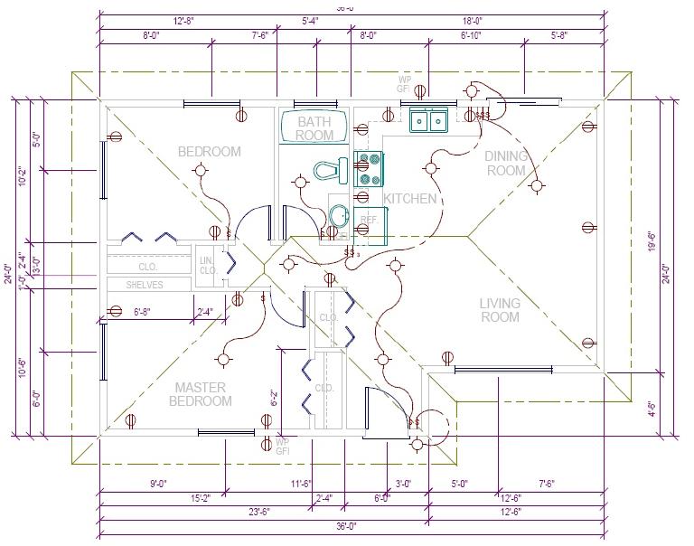
DIMENSIONING
DRAWN IN PAPER SPACE
Dude. This stuff MUST BE TIDY!
- DIMENSIONS are done on the DIMENSION layer in PAPER SPACE
- Did you DRAW lines in the MIDDLE of Interior walls earlier?
- We need them to dimension these walls.
- Lines on the “HIDDEN” layer do not show up when you print
- PAPER SPACE dimensions need MODEL SPACE lines to click on
- Otherwise you are dimensioning PAPER SPACE (that 30′ wall shows up as being 7.5″!).
- Did you DRAW lines in the MIDDLE of Interior walls earlier?
- USE SNAP at 12″ to space these away from the house. The 1st dimension line should be 48” (or 4’) away from any part of your house/patio/deck, each subsequent dimension should 12” (or 1’) further away
- This is pretty much the only time I use snap in AutoCAD.
- CAUTION: if you drew any LINES in paper space, AutoCAD will give dimensions based on the line you drew. If you wall comes up as 2″ and it should be 8′, you likely have a line drawn in paper space by mistake.
DIMENSION ROWS – outside *** Numbers read from bottom and right side ***
- 1st dimension line (4′ from building)– center of windows/doors and to outside of exterior walls
- 2nd dimension line (1′ away from 1st) – center of interior walls and to outside of exterior walls
- 3rd dimension line (1′ away from 2nd) – outside of exterior walls
- 4th dimension line (1′ away from 3rd) – overall size (outside to outside of furthest exterior walls)
- Dimensions – interior *** Do not dimension to interior doors ***
- Horizontal and vertical dimension line(s) to pick up any interior walls not dimensioned outside
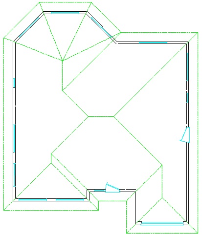
DRAWING THE ROOF
Level 1: I recommend a GABLE ROOF (easy)
Level 2: Do a HIP ROOF (option for level 1)
Level 3: Do a combination of both
DRAWN IN MODEL SPACE
- CHANGE to the ROOF layer with the Phantom line type
- OFFSET the outside walls out for the overhang, TRIM and EXTEND as needed (I cheat and FILET to a radius of “0”)
- Typically 6”, 12”, 18”, or 24”
- ALL overhangs are the same
- Draw 45-degree lines from corners for floor plan “kick outs.” Draw 45-degree lines from ALL corners to do a hip roof.
- THESE MUST BE ABSOLUTELY EXACTLY 45° OR THIS WILL.NOT.WORK.
- YOU CANNOT “WING THIS” Do you remember typing in EXACT angles in the tutorial?
- I taught you that for a reason!
- With complex roofs, be mindful of where the rain water will run to – Have it run AWAY from a wall, not TOWARDS a wall or INTO valleys that cannot drain.

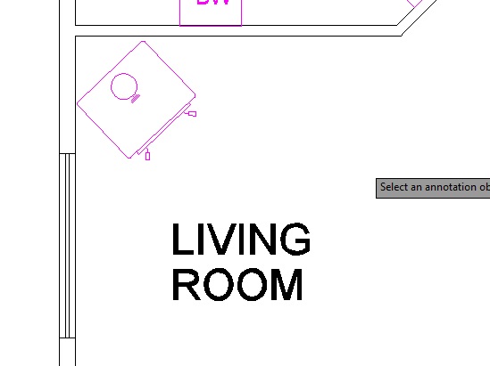
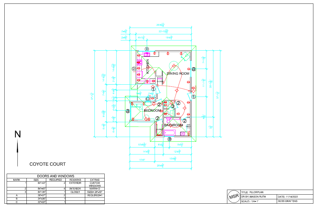
ROOM NOTATION
DRAWN IN PAPER SPACE
-
- CAPITAL letters only (we SHOUT here)
- ROOMS: text size 1/4″
- CLOSETS: text size 1/8″ or 3/16”
- NAMES:
- LIVING ROOM
- DINING ROOM
- KITCHEN
- BATH ROOM
- MASTER BEDROOM
- BEDROOM
- BATCAVE
- ENTRY
- CLOSET
- LINEN
- ETC
Make sure the lettering in your DOOR & WINDOW SCHEDULE is the SAME size text.
EXAMPLE
LAST CHANCE CHECKLIST
Check that you have everything that I’m asking for here.
Wellwood’s workshop floor plan (2015) as submitted to the Regional District
This is just….. odd:
Source: www.xkcd.com
HOW TO PRINT to see about printing a PREVIEW on 8.5 x 11″ (classroom printer) to check for errors. Get me to check!!
HOW TO PRINT to PLOT an ARCH D in (probably) SCALE: 1/4″ = 1′
Print out the MARK SHEET to make sure you have it all, and be ready for final plotting (we will plot all the drawings together at the end).
Next: ELEVATIONS