
[Automatics] [Differentials] [Engine Performance] [Boost & Nitrous] [Lifting & Lowering] [Balancing & Blueprinting]
QUESTIONS – Engine Performance |
|||||
The Compromise |
|||||
Magic Comes With a PriceIf you read anything, read this: Everything is a compromise. Anything you do to change what the factory produced, is going to cost you somewhere else. There is no “Free Lunch.” The best thing you can do, before you do anything, is to decide what your goals are. Do you want a more power? You have to accept a less fuel economy. Do you want more high rpm horsepower? You have to accept less low end torque. Do you want ultimate power? You must accept ultimate short engine life. Magic comes with a price; nothing is free. An engine’s life expectancy varies indirectly with the power it makes. Make a lot of power for a short time (22psi 10,000rpm turbocharged Honda), or make very little power almost forever (stock Dodge 318 V8). But we’re here for more performance. In the immortal words of Neil Young, “It’s better to burn out than to fade away.” We want power, whatever the cost.
The Secret to Making PowerIt’s air. The secret to making power is to get more air in the cylinders. Not more fuel: ~air.~ So everything we do to make power is trying to get more air into the cylinders. In this unit we will look at Naturally Aspirated (relying on atmospheric pressure only) modifications to make more power, in three stages: One thing to keep in mind, is that while many of these modifications may produce small improvements, collectively (that means “working all together”) they can produce significant results. Bolt On“Bolt On” parts are where everyone starts. These generally produce small gains, and they try to make it as easy as possible for the air to get into AND out of the cylinder.
|
|||||
INTAKE SYSTEM |
|||||
ULTIMATE GOAL: GET COLD, DENSE AIR, EASILY INTO THE CYLINDERFree Flowing Air FilterAdvantage: Improves air flow at all speeds. The best filters are cotton (such as K&N) instead of paper, and require a thin coating of light oil to aid in filtration. Cotton filter elements can usually be cleaned and re-used, however they should be inspected regularly for damage. The shape of the filter itself is irrelevant to performance, though a larger size would take longer to clog with dirt. While K&N filters physically have holes you can see light through, the pulsing action of the intake stroke causes the filter material to vibrate and “catch” the dirt out of the air. I was skeptical of this for a long time, but it works. Less restriction = easier cylinder filling Compromise: You usually get less filtration with more flow. This can lead to internal engine damage. Manufacturers will promise the world, but few can deliver. Do your research. Gain: Very small. You likely will not feel a difference.
Cold Air IntakeAdvantage: Provides a colder, denser air charge into the engine. Since an engine needs oxygen to help burn the fuel, if we can provide more oxygen, we should be able to burn more fuel and thus go faster. Cold air = dense air = more oxygen A 5L engine will draw in 5L air (this is the displacement of the engine). If we could get more oxygen molecules in that air, we could make more power, since oxygen supports combustion. Cool air is more dense – the molecules get smaller, and thereby take up less space. Since the Engine will still draw in the same fixed volume of air, cold dense air brings more oxygen molecules per volume into the engine! Some cold air intakes have been properly tested and tuned for length and diameter to provide a “ram” effect. Air has mass, and that mass in motion wants to keep in motion. We can use the momentum of the moving air to “stay moving” or “be already in motion” when the intake valve opens again, filling the cylinder better! Properly designed, a good intake system (from the filter to the valve) can actually fill the cylinder better than atmospheric pressure alone. ie: Momentum helps fill the cylinder over 100%. Cheaper intakes merely place an open-element filter inside the engine compartment. This is stupid! Now you are drawing in HOT air from the engine and radiator = zero benefit, and even LESS POWER! These are called a Warm Air Intake. Compromise: Cold air intakes often place the filter inside the fender or behind the front bumper. This can cause problems if you drive through a deep puddle, and the engine sucks in water. Water is not compressible, but the engine will try. This usually results in bent connecting rods and damaged pistons (hydrolocked) . These also tend to be much louder, but that is usually why we buy them in the first place 🙂 (I love them!). Gain: You might notice a difference, depending on how bad the stock intake system is.
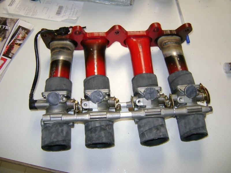
Below is the intake system I fabricated for The Sinister Sentra I used to own and race. The intake made only slightly more power, but was a LOT louder. Click for Video (and embarrassingly bad suspension – many changes followed this)
|
|||||
IGNITION SYSTEM |
|||||
|
Advantage: Provides a more intense firing of the spark plug. Some manufacturers are similar to factory ignitions, but provide more voltage and current, some spark the plugs multiple times during the power stroke, while others use a capacitor to discharge a large amount of voltage. Each one has its own advantage, you will need to decide which way you want to go. They perform the same function. Compromise: Other than requiring higher quality spark plug wires (and ensuring they are replaced when they age), there does not seem to be any significant disadvantage to a high intensity ignition system. Gain: On a stock engine, almost no improvement improvement. On a HIGHLY modified engine, almost mandatory! Do note: Modern ignition systems are pretty darned good as it is.
MSD Ignition “MSD” stands for Multiple Spark Discharge – this system takes the usual trigger input (review “IGNITION SYSTEM (Level 1)“), and instead of sending 12 volts to the ignition coil, discharges about 480 volts from a capacitor (much like a Tazer). Don’t Taze me Bro!Capacitors empty FAR, FAR faster than an ordinary trigger device, resulting in an even higher output from the coil. AND (oh yes, there’s more) instead of sparking the plug once, it sparks it about 30 times. If the fuel didn’t get burned with the first spark, the other 29 sparks will kill it. If you’ve ever been shocked by a running spark plug, you ain’t felt nothing yet. Improvement on my high-compression, snotty-cam Chevy V8? Not noticeable, but the spark plugs never got dirty…. Yeah, I’ve touched it. It hurts. A lot.
|
|||||
EXHAUST SYSTEM |
|||||
|
Advantage: Reduces exhaust restriction, allowing the engine to expend less energy “pumping” the exhaust out of the engine, AS WELL AS using that exiting exhaust to get the incoming intake charge a head start by “siphoning” it into the cylinder. An exhaust system will usually consist of Headers, flex joint, pipe, a Catalytic Converter, resonator, muffler and tailpipe. More air OUT = More air IN (After a heavy bout of diarrhea, you’re pretty hungry) Many people say “you need some back pressure.” They’re wrong. You don’t want Back Pressure, you want Scavenging (siphon action). Just like you can’t siphon gas through too large a hose, the exhaust cannot scavenge the cylinder through too large a tube. If you took ALL the exhaust off, right at the head (zero back pressure), the engine wouldn’t make ANY power, and wouldn’t even rev (I’ve done it. Loud as heck, though) – the exhaust does not leave the cylinder well, and the intake isn’t getting a head start help to fill the cylinder. Gutless turd. Saying your engine needs some back pressure is like saying your body needs to be just a bit constipated. Not true at all. How It Works: Exhaust Systems work by using the exiting mass of exhaust to “scavenge” or “siphon” the cylinder of exhaust AND help draw in air and fuel during “Overlap“. Overlap is when the exhaust valve is closing (often a little AFTER Top Dead Center of the piston), and the intake valve is opening (often a little BEFORE TDC of the piston). This period of “overlap” is critical for performance. C-R-I-T-I-C-A-L. C-R-I-T-I-C-A-L. Having the exiting mass of the exhaust help draw in the incoming air/fuel charge while the piston is essentially sitting still at TDC can benefit HUGE in fully filling the cylinder and making power. Tubing size should be sized according to the power you are going to make – the larger you go in diameter and the shorter you go in length, the more high-rpm power you make, and the less low-end torque you make. My rule-of-thumb: 1.6 – 2.0L = 2″ exhaust 2.5L = 2.25″ exhaust 3.0L = 2.5″ exhaust 5.0L = dual 2″ exhaust 5.3L = dual 2.25″ exhaust 6.0L = dual 2.5″ exhaust
Compromise: Headers tend to be noisier than the cast-iron manifold, and do not last as long. Stainless steel will last forever, but is very expensive. A low restriction exhaust system is also not a quiet one. Gain: You will likely notice a difference, depending on how bad the stock system is.
|
|||||
PARASITIC DRAWS |
|||||
Underdrive PulleysAdvantage: By slowing down the rotation of accessories (the stuff driven off the belts of the motor), you can free up some of the horsepower used to drive them. Also, a smaller pulley is a lighter pulley, and a reduction in rotating mass has an effect comparable to removing the same mass from the car, to the fourth power!! (double the rpm is quadruple the stress). Compromise: Everything runs slower, which could cause some problems with cooling, charging, a/c, and power steering. I have not yet seen an underdrive pulley that retains the “harmonic balancer” feature that the stock pulleys do. This may cause the crankshaft to fatigue and fail due to torsional vibration, more so on smaller, less “smooth” engines. The pulleys are also usually aluminum, which may wear rapidly against the front crankshaft seal (though a Speedi-Sleeve may fix that). Gain: Mildly noticeable.
Synthetic FluidsAdvantage: Synthetic fluids tend to be more slippery than dinosaur oil. Reducing friction frees up horsepower that would otherwise be lost. Synthetic oil also tends to be more durable in extreme conditions and longer lasting (thus requiring less frequent oil changes). Reduced friction loss = Horsepower gain Compromise: Approximately three times the price of dino oil, though the potential for extended service intervals may negate that disadvantage. On older engines there is the potential for the more slippery oil to slip past worn seals and cause oil leaks and oil consumption. Gain: Very small. You likely will not feel a difference. Poor Mumsie… My dear old mumsie decided to run synthetic oil in her old Toyota Corolla. Without checking with me. She did the math, and it despite the higher cost for the oil, the longer life of synthetic made it cheaper. However, she did not check for oil leaks and did not check the oil. Until the oil light came on because the oil had leak past the seals and rings (by the time the light comes on, the damage is already done). That got a lot more expensive than just running dino oil.
|
|||||
Bolt In |
|||||
Intake ManifoldAdvantage: Provides a larger, smoother, more direct and more uniform distribution of air or air/fuel) into the engine. There are two main parts to the intake manifold: The runners, and the plenum (joins the throttle body to the runners). The plenum is less important than you think. The runners are where the magic is. Air has “MASS,” and moving air has “MOMENTUM” – milk that! (That is an ongoing theme here). Once air is moving through a tube, that “column” of air wants to keep moving. The longer the column, the more the mass, the better the momentum. If the intake runner is long, the moving air can have so much momentum that it will continue to fill the cylinder even as the piston is moving UP, “ramming” itself in there! Woah! Larger diameter runners flow more air, but that air can get lost at low speeds and not fill the cylinder as well. Shorter runners are easier to get the air moving quickly, but have less “ram” effect at lower speeds (there is less “mass”), and not fill the cylinder as well. V8 intakes are often split into two categories (maybe three): Single Plane: An open plenum feeding short runners. Used for horsepower. Dual Plane: half the carb feeds half the engine, the other half of the carb feeds the other half, alternating sides by firing order. Used for torque. Another intake design is the Tunnel Ram, which has a large plenum feeding very long, direct runners (my favourite!). Take a look at ANY modern engine – there are LONG runners; they are all Tunnel Rams! Compromise: Intakes are designed to work at certain rpm ranges. The length and size of the runners are designed to operate at maximum efficiency at a certain range of air speed, and thus inefficient at other speeds. You may gain top-end power, but you will lose low-end power. A Dual Plane V8 manifold would be ideal on a 4×4 truck. A Single Plane manifold would be ideal on a light car with a big engine, preferably a race car. A single-plane/short-runner intake manifold tends to cost you useable torque everywhere except at the very very top of your RPM range. Gain: From moderate to significant, depending on how bad the factory manifold is.
CAUTION: I’M GOING TO NERD OUT HERE:
I like the “intimidation factor” of a Tunnel Ram. They are known for pulling incredibly strong throughout the rpm range. You will find many, many books, magazines, websites, and forums that say a Tunnel Ram is NOT a streetable intake system. Their complaints are: Poor throttle response Poor cold-start and cold-running Difficulty in tuning Poor fuel economy I disagree. These issues are (in my opinion) a result of using carburetors (or being unable to tune carburetors). Carbs require a decent vacuum signal from the engine to fuel accordingly, and having multiple carburetors reduce vacuum considerably. Reduced vacuum makes a carb want to go into the power circuit when cruising, and not want to draw adequate fuel while idling. Carbs also require heat to vapourize the fuel – the carbs on a tunnel ram are VERY far away from the engine heat, so cold-temperature operation is iffy at best. Throttle-response is hampered by the length of time it takes for the fuel to get from the carb’s accelerator pump and into the engine, hopefully before the fuel falls out of the airstream due to a lack of heat. All of these can be significantly reduce (and/or) eliminated by the use of port fuel injection, which can be tuned by Throttle Position Sensor (TPS, called “Alpha-N Tuning”) instead of Manifold Absolute Pressure (MAP, or “Speed-Density Tuning”). Look at every modern engine intake manifold – it’s essentially a tunnel ram. I intend to prove my theories on this in one of my up-coming projects. Stay tuned… Oh, and I found this:
|
|||||
CAMSHAFT |
|||||
THIS IS THE SINGLE MOST SIGNIFICANT CHANGE YOU CAN MAKE TO ANY ENGINE
Advantage: Changes valves timing to tailor the engine’s power to your desired outcome. Change this, and your engine WILL be different.
This To Consider: The valves are in the way of air flow – how can we get them out of the way? The valves are closed/closing while the air is still moving – can we keep them open longer? Can we get better siphoning (scavenging) action from the exhaust?
Camshaft design is a science in itself, and there is far, FAR more to learn about them than can be shared here. Generally, there are three different specs that are changed: Valve LiftThe single biggest restriction to air flow into the engine is the valves themselves. We can’t actually remove them, so we have to do something else. How about opening them really far and really quickly? Generally speaking, Lift tends to improve flow at all speeds, but “it depends” on the whole package of the whole engine, that is engine displacement, cylinder head flow, operating range, etc.. Piston, valve spring, valve guide and rocker arm clearances need to be checked when lift gets pretty big. A high-lift camshaft must open the valves very quickly to reach full lift before the valve has to close again. The biggest impediment to cylinder flow is the valve – you have this big valve that is just in the way. Since you can’t really do change the design, the best you can do is shove it open as far as you can so it is less of a restriction to flow. While high lift is fantastic for power, this can be very hard on the valvetrain (because in order to open the valve FARTHER in the same amount of time, you need to open the valve very quickly!), and may wear out rocker arms and valve guides more quickly. High lift and fast opening also require strong valve springs (or the valves will float really early – “floating” is when the valves stay open and kills power) – this accelerates wear on every part of the valvetrain. High lift is always good, but you also may need to machine the valve guide shorter, and/or machine the valve reliefs in the pistons deeper. Valve DurationWhat if we open the valves earlier, hold them open longer, and close them later? Duration is directly related to the engine RPM you expect to run. Commonly measured at a standardized 0.050″ lift, longer duration moves the power band higher, at the expense of idle quality and low speed driveability. Shorter duration camshafts move the power band lower, at the expense of high RPM power. We can improve high-rpm breathing if we can open the exhaust a little early, thus getting a head-start emptying the cylinder. We will use the momentum of the exiting exhaust to help “siphon” the intake charge into the cylinder by opening the intake valve while the exhaust valve is still closing (they are both open – this is normal – it’s called “valve overlap”). We can improve this scavenging effect at high-rpm by closing the exhaust valve a LOT later, (MORE overlap) which helps draw in a lot more air/fuel. We can improve the cylinder filling at high-rpm by closing the intake valve a LOT later, so that the momentum of the incoming air/fuel charge continues to fill the cylinder, even though the piston is on the way back up. In a nutshell: Open the intake early helps begin filling the cylinder, closing it later helps the momentum continue “ramming” itself in. Open the exhaust early gets a head start emptying the cylinder; closing it later helps “siphon” air and fuel in. More duration provides MORE TIME to get the job done, when you have LESS TIME in which to do it. THE DOWNSIDE: the intake and exhaust valves can open so early, be open so long, and close so late, that the air and fuel and exhaust get “lost” at LOW engine speeds, and idle quality and low-speed driveability and fuel economy suffer. Sounds sick though; I’ll still do it. Duration around 195° (@0.050″) will idle and perform essentially stock, around 220° (@.050″) will produce a noticeable “lope” to the idle, while 235° will be quite ragged. 255° ~starts~ to make power at around 4000rpm. Get too greedy after “that sound,” and you end up with a cam that won’t make power at speeds where your engine actually spends most of its time. The valves may be open so long that the air and fuel might sail right on out the exhaust. With big cams, the engine won’t create enough engine vacuum at idle to operate your power brakes, will make stop and go traffic with an automatic transmission a chore without a high-stall converter (a “loose” converter that engages at a higher rpm – makes it pretty lazy below the “stall speed”). The transmission may also shift late and hard like you’re at full throttle all the time because it thinks low idle vacuum is more throttle opening (engine load). Without a “tune,” an EFI computer (or carb for that matter) won’t know that the engine now has less vacuum, and flows more air, and may need better fueling to match the air flow, better spark timing to match the idle quality and better cylinder filling.
Lobe Separation (Overlap – My Favourite!)What if we increase the overlap – the time that both valves are open, so we can optimize for more engine scavenging? (the “siphoning” action that the exhaust does to draw in the intake charge). Yes. That is in the “Lobe Separation” of the cam lobes. Lobe Separation is how far apart the intake lobe is separated from the exhaust lobe in degrees.
The more you move the intake and exhaust cam lobes closer together, the later the exhaust valves will be closing and the earlier the intake valves will be opening. These valve closing and opening points often “overlap” – the exhaust is still closing as the intake starts to open! The closer the lobes are together, the more valve “overlap” you have (the intake valve always opens a few degrees before TDC to get a head-start on filling the cylinder, while the exhaust valve closes a few degrees after TDC to help the exiting exhaust help draw in the incoming air and fuel). Lots of valve overlap tends to make a mid-range torquey power curve, but also kills idle quality. Camshafts with lots of duration (high RPM) tend to have wide lobe separation angles (112° or more) to salvage some idle quality by limiting overlap. RV/Towing camshafts are comparatively short in duration (we don’t need to rev to the moon), but run much closer lobe separation (108° or even 106°) to maximize low/mid torque. Tight lobe separation (108° or less, my favourite!) will result in a very torquey power curve, a cool rough idle, but potentially less very top end power than a cam with 112° lobe separation.
Brian Tooley Racing is well known for “Truck Cams.” They made one they call “TRUCK NORRIS.” They advertise it as “Developed from hundreds of hours of in house cam lobe design and dyno testing, this camshaft has more power and torque everywhere in the curve compared to our legendary V2 truck cams.” And while there is magic in lobe profiles and ramp rates and all that, one thing to note is it has 107° lobe separation. So, like, Truck Yeah!
David Vizard (Mechanical Engineer and Engine Genius) even provides a formula to help chose the best Lobe Separation: 128 – (CID/#CYL/Intake-Valve-Dia * 0.91)
CompromiseThere is no camshaft that will “do it all.” You need to select the camshaft that will meet your needs, along with what you are willing to give up. The more rowdy the camshaft, the more modifications must be done to the rest of the engine to make it work and to make it last. Cams much over 222°@.050 will need higher compression ratio, deeper final gears, looser torque converter, headers, intake, and fuel system modifications, to get the most out of the engine, plus valvetrain modifications for survival.
Duration: High RPM power vs. Low RPM torque Lift: Air Flow vs. Valvetrain Life Lobe Separation: Maximum Power vs. Power Curve vs. Idle Quality
Gain: Anything you want. Sound bytes:
Mr. Wellwood’s ’77 Chevy – Howard’s Cams 231°/231° @ 0.050″, lobe separation of 108° (skip to 11:34) “The music of my people” Competition Cams Mutha Thumper (not mild, 235°/249° @ 0.050″, lobe separation of 107°)
Honda VTEC (Yo!) VTEC is an awesome invention. It uses TWO different cam lobes, whose Valve Timing is Electronically Controlled. This allows a small duration, low lift, wide separation angle cam to be used for low speed, smooth driving, and economy, and then switch to a long duration, high lift, narrow separation angle cam for high speed power. Phenomenally successful.
Other manufacturers have done similar things, (such as Nissan, Subaru, Mazda, Toyota, GM, and many others) advancing or retarding one (or both) intake cams to change overlap and thus power curve.
One thing leads to another… Below is the “Cam Card” for a camshaft I chose for an engine I built for a half-ton truck.
I wanted it to sound meaty (231°@0.050″, 108LSA), yet still be “driveable,” with strong mid-range torque, and be easy on the valvetrain. This cam does just that. It’s a bit “old-school” in design, but it works fine. Just to make this camshaft work, these are the modifications I did to the motor: Compression Ratio: changed from 8.0:1 to 10.9:1 (this is a RADICALLY HUGE change) Dished pistons changed for flat-top pistons Cylinder heads changed from 78cc chambers to 60cc chambers Steel shim (0.015″ thick) head gaskets installed Valve Springs: Stronger and taller Valve Spring Keepers: 0.050″ Offset keepers to raise the installed height to fit the taller springs Exhaust Rotators: Removed (heavy) and replaced with standard retainers (light) Valve Spring Shims: 0.015″ spring shim added to make up the increased height caused by removing the exhaust valve spring rotators Indexable Timing Chain: Installed to ensure correct cam timing (cam needed to be installed 6° advanced – see Balancing & Blueprinting) Screw-In Rocker Studs: Heads machined for screw-in studs as the stock “pressed-in” studs will pull out under the higher spring pressure Roller Rocker Arms: Rigid rocker arms that will not flex with the higher spring rates AND…. To make the engine idle in gear, I needed:
I COULD HAVE BEEN RICHI figured I would be rich if I could develop a way of controlling valves by electronic solenoids instead of a camshaft. Each valve could be independently controlled, and could be run to bring maximum power throughout the entire RPM range with ZERO compromise whatsoever. Better than VTEC. I was going to be RICH! Curse you, Koeningsegg.
|
|||||
COMPRESSION RATIO |
|||||
FEEL THE SQUEEZE!All things being equal, the more you compress the air and fuel, the more heat you put into the air and fuel, the bigger the combustion power will be. This is a very good thing for power AND fuel economy. There are practical limits – once the fuel starts exploding by itself (instead of burning in a controlled manner), DAMAGE occurs (this “detonation” sounds like a diesel). Running High Octane gasoline can help reduce this chance. The “Compression Ratio” is the amount the mixture is squeezed on the compression stroke. All other things being equal, the more the fuel/air mixture is compressed, the more power AND the more fuel economy the engine produces As the mixture is compressed, it becomes hotter. If it becomes hotter than the flash point of the fuel, the fuel explodes prematurely (instead of controlled burning), and engine damage results. This is called pre-ignition, or detonation; or more commonly, knock, or ping. Detonation will blow holes through pistons – you will see melted aluminum in your spark plugs. This is the limiting factor to how far you can go with increasing compression ratios.
A typical compression ratio might be 10:1 10 units of air/fuel squeezed into 1 unit of air/fuel
Compression Ratios of Different Engines:4:1 Vintage cars – because of poor quality of fuel, and hand crank starting system 8:1 – 10:1 Modern Production Cars – higher compression ratios with computerized engine management to prevent knock and ping. Up to 12.5:1 Muscle Cars from the late 1960’s – until low emissions became more important, compression ratios were reduced, to reduce NOx (Learn about Emission Controls) Up to 17:1 Race Cars – because they use better quality high octane gasoline or alcohol Up to 25:1 Diesel Engines – diesels take only air in on the intake stroke, and use the high temperature of the air on compression stroke to ignite fuel which is injected directly into the combustion chamber Did you recognize this text as a direct copy-and-paste from Level 1?
Increased Compression RatioAdvantage: Increases the power of combustion by compressing the air and fuel molecules closer together, putting more heat into the charge. Compression tends to increase power throughout the rpm range, AND improve fuel economy too. Compromise: Requires engine disassembly to install either high compression pistons, or small chambered heads. Either too much compression or poor ignition timing curve can cause pre-ignition and/or detonation which will destroy pistons. Piston skirts may be scored by the cylinder walls under pressure. Inadequate cooling system may cause the now hotter engine to overheat. Requires high octane gasoline. More difficult to crank the engine over. Gain: Significant gains throughout the rpm range can be had.
LIVING ON THE EDGE (NERDING OUT ON YOU)A previous daily driver of mine had a Chevy 350 cubic inch V8 engine, with iron “wedge” heads, running a tick under 11:1 compression. On paper, this engine shouldn’t survive on pump gas (you should not run more than 10:1), but it does. And makes GOOD POWER too! How can this be? “Quench” The piston at TDC is 0.040″ away from the head surface – this is called “Quench,” and is critical for good combustion and detonation resistance. You want that distance to be 0.040″. Too far away, and even a low compression engine may experience detonation (two flame-fronts colliding; one from the spark plug, and another self-induced; very damaging to pistons). Too close, and the piston might contact the head at high RPM as everything inside the engine stretches. Yes, stretches. The combustion chambers have been polished to remove any potential “hot spots” caused by sharp edges or poor casting. Carefully modified Ignition Spark Advance to keep the timing advanced enough to reduce combustion temperatures (too retarded, and the flame “chases” the pistons down the hole, heating up the cylinder walls), but not so far advanced to build cylinder pressure TOO quickly and detonate.
LET’S TALK OCTANEThe TV commercials want you to buy High Octane “Premium” Gas. “Octane” is the gasolines measured ability to resist detonation (igniting by itself without the spark plugs). That is all. It does not burn faster, or slower, despite what you read on the interwebs. If your engine is designed for a high-octane fuel – run it! Almost ALL modern engines have sensors (Knock Sensors) that “listen” for detonation (knock), and will “de-tune” your engine if it hears it. This WILL cost you power and fuel economy ….though the gas is certainly cheaper. Whether you save enough money at the pump to offset the worse fuel economy is something you need to work out for yourself. If your engine is designed for a low-octane fuel – don’t waste your money putting in the Premium fuel, despite what the commercials say. It will not make more power. If you have a turbocharged or supercharged engine – run the high-octane Premium gas. Always.
|
|||||
INTERNAL PARASITES |
|||||
|
We can reduce or eliminate the things that slow your engine down from the inside: Windage TrayAdvantage: Captures stray oil spray, preventing it from getting in the way of the spinning crankshaft Compromise: Extra cost, and may require a custom oil pan to fit. Gain: Very small. You likely will not feel a difference.
Crank ScraperAdvantage: Very close-fitting sheet metal strips away oil on spinning crankshaft and connecting rods, reducing rotating weight, as well as reducing “windage.” Compromise: Extra cost, requires very accurate fitment. Gain: Very small. You likely will not feel a difference.
|
|||||
Modifications |
|||||
De-BurringAdvantage: Removal of casting flash inside the engine block and cylinder heads to aid in rapid oil drain back, resulting in less windage (oil flailing around in the crankcase, slowing the crankshaft down), and less lost horsepower. Having the engine oil get back into the oil pan quickly means it is there for the engine to pump – important at high RPM where you might be pumping oil out faster than it returns. Another personal advantage is the removal of sharp edges that can cut you during assembly/maintenance. Compromise: Exceedingly time consuming. Gain: You will not feel a difference.
|
|||||
CYLINDER HEAD WORK |
|||||
PortingAdvantage: Provides a smoother and better flowing passage for the air to travel through. Sometimes we port heads larger, but too large and the air can get “lost” inside and reduce power! Think of air as a fluid like a waterslide, and you want to make the flow of this fluid as easy as possible – this increases the breathing of the engine and thus, more horsepower. A simpler method of porting is called Port Matching where the first 1″ of both the port and manifold are enlarged to match the gasket opening. Most engines can use a bit of help on the exhaust side of things (Nissan GA16DE, Ford 302, etc.). Compromise: If you make the ports too big, you may reduce low speed power due to a reduction of port velocity. Without knowing what you’re doing, you can ruin a set of heads by being too greedy. Difficult to know how close to a coolant passage you are when grinding. Same engines SHOULD NOT be ported, as their heads breathe too much to begin with (Toyota 4AGE “Big Port”, Ford 351C, etc.), and in fact, are often reduced. Exceptionally time consuming. Gain: From moderate to significant, depending on how bad the factory ports are. ARTICLE-DIY-Head Porting (Grassroots Motorsports Magazine)
PolishingAdvantage: Provides a perfectly smooth surface inside the intake and exhaust ports to improve flow. Compromise: Smooth port surface reduces air stream turbulence which may reduce combustion efficiency. NOT recommended on carbureted or Throttle Body Injected cars, as the lack of turbulence allows fuel to fall out of suspension of the air stream. Usually combined with Porting. Gains: Polishing alone, Very small. You likely will not feel a difference.
I will polish EXHAUST ports, since there is no fuel that needs to stay -in- the air. I leave the intakes “as cut” by the carbide cutter or rough sanding roll that I use to shape the ports. For intake I focus more on a smooth PATH instead of a polished FINISH. For intakes, ROUGH is good.
Extrude HoneAdvantage: Passages are shaped by an abrasive putty force fed through the component. Putty is a “fluid,” and shapes existing ports and passages in the manner that best suits the existing shape of the ports. Compromise: Very expensive. Gain: From moderate to significant, depending on how bad the factory ports are. EXTRUDE HONE I once priced out getting factory a (1) cast-iron exhaust manifold extrude-honed. That way, the engine could look “stock,” but actually make significantly more power. Kind of a “cheater motor” if you will. It would have cost $800 at the time (2002). I said “no thank you.” Apparently, though, you can fill a manifold with hydrosulphuric acid, and let the acid etch the metal away, making the passages bigger and flow more air. When complete, it will still look cast, not machined (a good way to cheat, if you want it to “look” stock). Still, this fascinates me.
|
|||||
CRANKSHAFT MODS |
|||||
Knife-EdgingAdvantage: More “aerodynamic” shape cuts through air and windage easier. Lighter counterweights allow more rapid acceleration. Compromise: Requires complete re-balancing. Lighter crankshafts have a harder time maintaining momentum at low speeds, taking off, and pulling hills. Aggressive machining could weaken crankshaft. You might not want this done on a street engine. Gain: Mild to moderate, depending on how bad the factory parts are.
|
|||||
THERMAL & FRICTION COATINGS |
|||||
CoatingsAdvantage: Relatively new, special coatings can be used to reduce friction, withstand heat, and prevent corrosion. Dry film coatings on piston skirts help reduce sliding friction, while ceramic coatings on piston heads help keep the heat of combustion in the combustion chamber where we need it. Other coatings help shed oil quickly. Compromise: Somewhat expensive. What happens if the coating(s) chip off? Gain: Very small. You likely will not feel a difference. But the increased longevity is a real thing.
|
|||||
PISTONS |
|||||
Cast AluminumMolten aluminum is poured into a mold, the aluminum cools, and hardens. The casting is then machined. Cast aluminum pistons have a crystalline structure which is not very strong and does not handle abuse. Steel bands are often inserted in the mold when the piston is cast to control expansion of the skirt area when the piston heats up. This allows piston to cylinder wall clearance to be set closer, and therefore a quieter engine with less piston slap. Advantage: Cheap, quiet and good sealing. Compromise: Weak. Cannot handle high compression, boost or detonation. Gain: No performance gain in and of itself
Forged AluminumA solid slug of aluminum is pressed very quickly and forcibly into a die. The resulting forging is then machined to shape. Forged pistons have a grain structure rather than a crystalline structure which makes them much stronger and able to take more punishment. However, because they are more dense, they are also more heavy. Forged pistons have no expansion control, and must be fit looser in the cylinder to accommodate for their expansion. This causes forged pistons to be noisy (PISTON SLAP) and burn more oil (CLEARANCE) until the engine has warmed up and everything has expanded. Advantage: Significantly greater resistance to fatigue and detonation damage. The standard for a race engine. Compromise: These pistons are a lot more dense, and they expand more as they heat up. This requires a greater piston to cylinder clearance on assembly, which will clatter when the engine is cold. It may also have increased oil consumption when cold. Gain: No performance gain in and of itself, but they will take abuse!
Hyper-eutectic ( high pressure ) Cast AluminumA good compromise between forged and cast pistons, is casting using high pressure. This type of piston has relatively light weight, steel expansion bands, and is just about as strong as forged pistons Advantage: Quiet, good sealing, good resistance to fatigue. Excellent piston for a street driving car. Compromise: Does not like detonation AT ALL (forgot what detonation is? Go back and read Compression Ratios) Gain: No performance gain in and of itself, but stronger than cast.
|
|||||
CONNECTING RODS |
|||||
Heavy Duty Rod BoltsAdvantage: A high quality, high strength connecting rod bolt allows a higher sustained engine rpm without failure. High RPM tries to “stretch” the rod bolts. At some point, they may stretch too far, and break. The forces on an engine as the RPM increases are EXPONENTIAL. To ensure proper torque when tightening them, rod bolts are measured with a micrometer for stretch instead of with a torque wrench for twist (tiny defects in the thread will give a false torque reading). Compromise: Added cost, and they require specific machining: HD bolts distort the connecting rod differently than the original bolts do, so the connecting rod needs to be machined properly round again (called “re-sizing”). This is an added cost, but WELL WORTH IT. Gain: No performance gain in and of itself
Polished RodsAdvantage: Reduces the likelihood of connecting rod failure by removing any surface imperfections that could become stress risers. Rod should be ground and then high-speed sanded along the length of the beams, not across them. Compromise: Time consuming; engine requires complete disassembly; engine must be re-balanced Gain: No performance gain in and of itself
|
|||||
SYNOPSIS |
|||||
|
While many modifications provide very small gains, cumulatively the results will be noticeable. If you do ALL the things listed here, you will indeed have a powerhouse of an engine. There are other things engine builders do that are not listed here, but these are generally the big ones. YouTube channels I follow on Engines:
|