
[The Engine] [Cylinder Heads] [Engine Blocks] [Fuel System] [Ignition System] [Cooling System]
CLICK HERE FOR QUESTION SHEETLatest update: 2025/11/18 |
||||||||||||||||||||||||||||||||||||||||||
|
The FUEL SYSTEM is ONE of the TWO engine support systems that is CRITICAL for both POWER and ECONOMY. Yes, you CAN have both and you HAVE both – it all comes down to YOU!!
Things we’re going to look at:
|
||||||||||||||||||||||||||||||||||||||||||
PURPOSE |
||||||||||||||||||||||||||||||||||||||||||
|
THE PURPOSE OF THE FUEL SYSTEM IS: To control the speed of the engine for different operating conditions. To supply the right amount of fuel for the engine to burn under different operating conditions. Mr. Wellwood’s Classroom Lesson:
|
||||||||||||||||||||||||||||||||||||||||||
CONTROLLING SPEED |
||||||||||||||||||||||||||||||||||||||||||
|
How do I make an engine “rev up?” On the Intake stroke as the piston is moving down, air is drawn into the cylinder, or more accurately: Atmospheric Pressure PUSHES the air in to fill the growing air space. To reduce the engine speed (for all spark-ignition engines), we restrict the ability of air to get into the cylinder, usually by closing it off with a “throttle plate” or something similar. Atmosphere WANTS to get in there, and we’re PREVENTING it. As we un-restrict the flow of air into the cylinder, Atmospheric Pressure rushes in to fill the cylinder, more fuel is added, the engine makes more power, and the engine speed increases. So, think of it that we SLOW THE ENGINE DOWN, instead of SPEEDING IT UP You can have one throttle plate, or multiple throttle plates in the passageway into the engine. These passageways are often called “barrels.” In the image below you see a 4-Barrel Carburetor. The two smaller “barrels” are the “Primaries,” and provide good throttle response and economy driving around town. The two larger “Secondaries” open at about 3/4 throttle, and provide POWER (but NOT economy).
Does this make sense? For giggles, Giggity-Google “slide throttle” (both plate and cylinder) and “roller throttle” for some interesting and alternative ideas on controlling engine speed
|
||||||||||||||||||||||||||||||||||||||||||
RIGHT AMOUNT OF FUEL |
||||||||||||||||||||||||||||||||||||||||||
BRAIN BLOWER #1:FUEL IS NOT POWER, AIR IS POWER
Air and Fuel are mixed by WEIGHT. If you have 1lb of air and 1lb of fuel (“lb” means “pound”), you would have a 1:1 fuel RATIO. 1:1 will NOT run an engine, because gasoline needs more air than that. A LOT more. Gasoline can burn pretty much anywhere between 8lbs of air to 1lb of fuel, all the way up to 16lbs of air to 1lb of fuel, but somewhere in there is a “Perfect Mixture” of Air:Fuel. That wide range of allowable mixture is part of what makes gasoline pretty dangerous. A “perfect mixture” of air and fuel for “perfect combustion” is called a “Stoichiometric” mixture. You might have heard that term in your Chemistry Class; this is Chemistry. A Stochiometric Mixture provides the most complete combustion – this is very good for reducing pollution!! Gasoline’s “Stochiometric” Mixture is 14.7 lbs air : 1 lb fuel (14.7:1)If you burn more fuel than that, your engine is running “RICH” or “FAT.” If you burn less fuel than that, your engine is running “LEAN.” NOTE:
BRAIN BLOWER #2:LIQUID FUEL DOES NOT BURN – VAPORIZED FUEL BURNS
Ever spilled gasoline? It evaporates a whole lot faster in the summer than winter, eh? To vapourize liquid fuel, we need HEAT. When the engine is cold there is very little heat, so not much fuel vapourizes. Except we need vapourized fuel. SOME fuel vapour will happen, but not enough to run the engine, so… To fix this, we throw in a whole bunch of extra fuel (run really rich) so that collectively, enough little bits of fuel will vapourize enough to run the engine. Your engine might be as rich as 8:1 during cold start! NOTE: It will absolutely NOT like running at 8:1 when everything is hot We want maximum fuel efficiency when we are cruising (where we are doing the most driving) – so we want “just enough fuel” to run ok. Many engines can run around 15 or 16:1 lean under cruise conditions. But maximum efficiency is NOT maximum power – For maximum power we want “ALL the fuel we need.” This is 12.6:1 for most gasoline engines, even richer for turbocharged engines (upwards of 11:1). The extra fuel also helps “cool” the combustion, so the combustion doesn’t start eating the motor as well Combustion wants something to eat – if it’s hot enough, it will eat pistons and valves just as easily as fuel! Note: MORE fuel is not more POWER – the CORRECT amount of fuel is needed for maximum power.
“STOICHIOMETRIC” – means “the perfect mix” of air to fuel (by weight) for perfect combustion. Not all fuels share the same mixture.
|
||||||||||||||||||||||||||||||||||||||||||
TYPES of FUEL |
||||||||||||||||||||||||||||||||||||||||||
|
There are a variety of different types of fuels used in motor vehicles: Hydrogen Has not become mainstream yet, though many manufacturers have something available. Fuel sources are uncommon. It does not provide very much power, and there are some storage limitations. Stoichiometric: 34.3:1 (best fuel economy) Gasoline Ye Olde favourite. Made from Dinosaurs (oil). Not really good for the Earth. Stoichiometric: 14.7:1 Propane “Liquified Petroleum Gas” (LPG). My favourite, essentially 120 octane and almost zero pollution (forklifts run propane INSIDE warehouses, and nobody dies from the exhaust!). It’s a very clean burning fuel, but doesn’t work well when it’s really cold outside. Because Propane as less HEAT ENERGY, you end up working the engine harder, and burning MORE propane than you would with gasoline, despite a leaner air fuel ratio. Build an engine FOR propane, and it works great! (high compression AND boost kind of thing). Stoichiometric: 15.67:1 Natural Gas “Compressed Natural Gas” (CNG) Essentially 130 octane but is VERY high pressure and requires VERY thick and heavy pressurized cylinders to contain it, you get limited range, and less power than gas. Years ago there was ONE fueling station in all of Kelowna. In theory, you could refuel off the natural gas line in your home. Stoichiometric: 17.2:1 Ethanol Very clean burning, often made from corn (renewable), nice to the environment, essentially 100 octane, but you’ll burn a LOT more of it than gasoline (poor fuel economy). A challenge to run in a carburetor, as it is highly influenced by atmospheric pressure, temperature, and humidity. Caustic to the fuel system components, especially rubber – you’ll want plastic gas tanks, polyethylene-lined fuel lines. Our gasolines are usually 5-10% Ethanol. I’d love to get E85 here – 85% ethanol; what a POWER fuel! Stoichiometric: 9:1 (Our gasoline is 5-10% Ethanol-enriched gas means you are that much closer to this worse fuel economy fuel! But it is a little bit better for the environment) Methanol Very much the same issues as Ethanol, but may be more refined hydrocarbon sourced, or bio-mass sourced. Essentially 110 octane. Exceptionally caustic to metals, it can cause problems in the fuel system. Stoichiometric: 6.47:1 (the worst economy – you will burn 2.25 times more fuel than gasoline!) Diesel I always joke that “Diesel is not the answer, Diesel is the question. The answer is ‘No’.” But seriously, Diesel excels in heavy loads, hauling, long distance, great torque, and great fuel economy. It does tend to have particulates in the exhaust (the soot you see), and governments have tried banning Diesel in cities to try and reduce particulate pollution. The great torque and fuel economy makes it the best choice for Big rigs, Locomotives, ships, and anything that really needs torque and economy. Having said that, if I were to buy a big crew cab dually to haul my race car or a 5th wheel all around the country – it will be Diesel. Stoichiometric: 14.5:1 Nitro Methane (this is “Funny Car” fuel – NOT for your street car!) You should Google this stuff. It’s hilarious. And smells AWESOME. This will NOT be on the test. Google its Stoichiometric Ratio!
We will focus mainly on traditional Gasoline systems.
|
||||||||||||||||||||||||||||||||||||||||||
TYPES of FUEL SYSTEMS |
||||||||||||||||||||||||||||||||||||||||||
|
Two types of fuel systems have been used in gasoline engines in modern times: Carburetors – 1890’s technology. Relies on atmospheric pressure and engine vacuum to provide fuel to the motor through metered orifices (called “Jets” – holes that are sized to only allow the correct amount of fuel to pass). The last carburetors in factory production were the very early 1990’s trucks. Carburetors have been working just fine LONGER THAN FUEL INJECTION HAS EVEN BEEN AROUND. You might never own or work on a carb in your life!!
Fuel Injection – Operating conditions are “read” by various sensors, a computer calculates the correct amount of fuel and controls electrically-controlled orifices (called “Injectors” – their “on” and “off” time can be varied) which provide fuel under pressure. Fuel injection started as being MECHANICALLY operated in about the 1930’s and primarily used in Diesel applications, it started running Gasoline in about the 1950’s. Mechanical Fuel Injection was pretty simple, but it did the job back then. Fuel injection went ELECTRONIC really seriously in the 1980’s. EFI (Electronic Fuel Injection) is what you will see in everything today. Diesel started going Electronic in the late 1990’s.
|
||||||||||||||||||||||||||||||||||||||||||
OPERATING REQUIREMENTS |
||||||||||||||||||||||||||||||||||||||||||
|
An engine must operate under a wide range of conditions, temperatures and loads. The fuel system must be able to provide for these conditions as they are needed. The ratio of Air to fuel will need to be anywhere from 8:1 to 15:1 by weight. 14.7 lbs of air to 1 lb of fuel We are not used to thinking about air as having weight, so if it was described by volume: 15,000 Liters of air to burn 1 Liter of fuel Perfect combustion happens with an air-fuel ratio of 14.7:1 Unfortunately, engines idle smoother if they are a bit rich, make the best power quite a bit rich, and get better fuel economy running a bit lean. *LEARN THIS TERM:The Air Fuel Ratio is important to the running of our engine. We use the term “AIR/FUEL RATIO” (AFR) a lot in both Carburetors as well as Fuel Injection SIX OPERATING CONDITIONS:Cold Start:Liquid fuel does not burn, only vapourized fuel burns. For fuel to become a vapour, we need heat. This is a problem when we start a cold engine (a cold engine isn’t hot), even worse when it’s cold outside (not hot). Since only some fuel will vapourize when everything is cold, “Cold Start” dumps a crap-ton of fuel into the engine in the hopes that enough of it will vapourize enough to run. I have seen some Cold Starts run as rich as 8:1! RISK: Cold Running means you are flooding the cylinders with un-burned extra fuel. This washes away oil which accelerates engine wear, thins out the oil which accelerates bearing wear, and that rich mixture is also building up carbon deposits in your engine and polluting your oil. You have everything to lose by running too rich!
Idle:Usually provide a rich mixture (12-13:1) for a SMOOTH idle, but many manufacturers today strive for 14.7:1 idle for emissions purposes. Low Speed:Provide a slightly rich mixture (13-14:1) to operate smoothly at low speed, but many manufacturers today strive for 14.7:1 low speed for emissions purposes. Cruise:Provide a stoichiometric mixture (14.7:1) to improve economy in low/no-load conditions. Some manufacturers shoot for a slightly lean mixture (15-16:1) for even better fuel economy.
High Speed & Power:Oh, I like this part… Full-Throttle puts maximum strain on the insides of your motor. Extra fuel helps to “cool” the rings, pistons, and valves, helping them not to “burn” under the extra strain of full-power combustion. “High Speed” uses a rich mixture (about 12.6:1) to improve power and protect the engine. Boosted engines run even MORE fuel (11.5:1 or even richer) to help cool the cylinders down so that the pistons don’t become fuel.
Acceleration:Provide a squirt of extra fuel (maybe 8:1?) to prevent the engine from stumbling as the throttle is opened quickly I tune this to only be as rich as the engine needs to not stumble; I don’t look at numbers
|
||||||||||||||||||||||||||||||||||||||||||
TERMS |
||||||||||||||||||||||||||||||||||||||||||
Atomize:To turn liquid fuel into tiny droplets to aid in vapourization. Liquid fuel does not burn. Vapourize:To turn atomized fuel into a fine mist using heat to aid in combustion. Vapourized fuel burns. Rich:More fuel delivered than the engine can burn properly (a rich engine will feel “sluggish,” and may backfire through the exhaust) Lean:Less fuel delivered than the engine can burn properly (a lean engine may “surge” instead of run smooth, and may backfire through the intake) Stoichiometric:The ideal mixture of air to fuel (14.7:1 by weight) for perfect combustion (not “best power”) Flood:So much fuel delivered that the engine will not start or run – the spark plugs will be wet and dripping with fuel. (You fix this by putting your foot to the floor (wide open throttle) and cranking the engine over so it breathes in LOTS of air, and NO fuel, until it evaporates enough fuel to start) Throttle:A movable plate that controls the engine’s intake of air, thus regulating engine speed Choke:To restrict airflow into the engine such that additional fuel is drawn in through every available fuel port in the carburetor (carbureted systems only) Engine Vacuum:A low-pressure area beneath a closed or partially closed throttle. We don’t normally see a “perfect” vacuum, but we do see air pressure less than atmospheric pressure Do you remember looking at Vacuum Tests in The Engine? We check this. A typical engine idles at around 18inHg of vacuum Vacuum measurement comes from “how high can this engine suck liquid Mercury up a tube” (inHg = inches of Mercury) Since this is Measured in the “Manifold,” and since the Atmosphere is kind of “Pressing” itself into the engine, we call this “Manifold Pressure“ Manifold Pressure*:Air Pressure as measured within the intake – it may be full atmospheric pressure (when the throttle is wide open) or less Atmospheric pressure is 14.7psi = 100kPa = 1BAR One my other engines idles at 40kPa, which is 60 less that atmosphere, which means “vacuum.” Anything LESS than full atmospheric pressure is a “vacuum” *LEARN THIS TERM:Since Atmospheric Pressure is kind of an ABSOLUTE PRESSURE here on Earth (it does not change), and since we are measuring the amount of Atmospheric Pressure that makes it into the Intake MANIFOLD, we call this “MANIFOLD ABSOLUTE PRESSURE” (MAP). We use this term a lot in Fuel Injection
Traditionally, engines used a mechanical device called a Carburetor to get the fuel into the engine. Let’s see how that works:
|
||||||||||||||||||||||||||||||||||||||||||
CARBURETOR OPERATION |
||||||||||||||||||||||||||||||||||||||||||
|
First, we need to be able to control the engine speed. For this, we can either allow air to get into the cylinder, or block it off partially or completely. This is the throttle, and is usually a flat rotatable disk that is controlled through linkages or cables by your foot. The Throttle restricts. If the throttle is completely closed, the running engine will be sucking against the bottom of the throttle plate. It is easy, then, to have fuel drawn out through a port just below the throttle plate. This works great for idle, and with a few more ports low-speed can work for us. Because the Vacuum is inside the manifold, we call this “Manifold Vacuum“ Because a Vacuum is really LESS than Atmospheric Pressure, we really have LOW “Manifold Absolute Pressure“
When the throttle is opened all the way, there is nothing for the engine to suck against. Running fuel to a port won’t work. Well…. we can “fake it” in a way…. BRAIN BLOWER #3:AIR HAS MASS*We use its moving mass to make the fuel system workLet’s put a uniquely-shaped restriction (called a Venturi, a practical application of Bernoulli’s Principle) in the way of the air flow through carburetor such that the air rushing into the engine sort of gets squeezed at this restriction. Since that moving air has MASS, and since that MASS is being PUSHED through a SMALLER passage, that air has to move FASTER through the restriction. Like when you put your thumb over the garden hose and make the water spray faster! It gives up some of its pressure for speed – this loss of pressure is like a vacuum. It will be “lower than atmospheric pressure” for sure. If we port some fuel in the restriction right where the air speeds up, the loss of pressure (now a vacuum) will draw fuel into the airstream. *LEARN THIS TERM: Since Air has MASS (you can feel it when you have your arm out the window of a moving car), and this MASS is being pushed into the engine as a FLOW of AIR, we call this “MASS AIR FLOW” (MAF). We use this term a lot in Fuel Injection Notice the “Main Jet” in the bottom of this picture. We can’t just dump fuel all willy-nilly and hope it works, we need to accurately meter the fuel. A “main jet ” is added to the bottom end of the main discharge nozzle to limit the amount of fuel. A jet is just a screw-in brass plug with a hole drilled through it. The larger the hole is, the more fuel it will pass, and the richer the engine will run. If you want a leaner air/fuel ratio, put in a smaller main jet.
What the heck is that restriction in the carburetor anyway? Bernoulli’s principle (Daniel Bernoulli 1700-1782) states “when the speed of an air stream increases, its pressure decreases” (Though not a perfect explanation. See HowStuffWorks.com). What this means is that if you force a stream of air to speed up, a vacuum is created in it. This is the same principle that allows airplanes to fly. The top of the wing is a curved surface, while the bottom is flat. As the wing moves through the air, the air moving over the wing speeds up, while the air moving under the wing stays the same speed. This creates a vacuum over the wing (lift). When the lift is greater than the weight of the aircraft, it will fly.
In the same way, a race car uses an upside down wing to provide downforce:
ABOVE:My friend Joe Cheng stacks three wings on the front and three wings on the back of his Autoslalom race car. As long as you stay above 90km/h, there is enough downforce pushing you into the ground to make the corner. If you get scared and slow down for the corner, you lose the air speed, you lose the downforce, you lose the grip, and you won’t make the corner. Strange, eh?
A wing won’t help us feed our engine, but a tube will. If you could wrap a wing into a tube, it would look like this.
A restriction in a tube like this is called a Venturi, and when air has to flow through the restriction, it has to speed up. An increase in speed causes a reduction in pressure (like Lift, only directed towards the center of the Venturi). If we pipe fuel into the middle of this low pressure area, fuel will be sucked into the engine.
|
||||||||||||||||||||||||||||||||||||||||||
CRUISE |
||||||||||||||||||||||||||||||||||||||||||
|
All this would work fine for an engine that only runs at one speed. High speed. Wide Open Throttle (WOT). While I like that, RCMP Constable Rigby does not. We need to control engine speed! The easiest way is to put a shaft through the body of the carb, and placing a disc on the shaft. This is the “throttle plate”. When it is placed across the air horn, it restricts the air flow and therefore, engine speed. When the plate is moved parallel to the air flow, there is no restriction, and therefore, the engine speeds up. At around HALF-Throttle, there is enough Mass Air Flow (air speed) through the Venturi for air to be drawn into the air stream (Air Flow). There might even still be a little vacuum sucking some fuel in through the idle ports as well. Cruise is usually tuned for minimum emissions and maximum economy …. but not really safe for full throttle (that’s coming up)
TUNING TRICK: Notice the box-looking thing in the fuel bowl – it’s called a “float.” As the fuel in the bowl is used, the float drops, opening a passageway for fuel to fill. Just like a toilet bowl when you flush, actually! You can tune the ENTIRE carb’s fuel mix by setting the float high (Rich = it is easier for fuel to get sucked in), or low (Lean = it’s harder for the fuel to get sucked in).
|
||||||||||||||||||||||||||||||||||||||||||
IDLE |
||||||||||||||||||||||||||||||||||||||||||
|
Notice, though, that if the throttle closes, there will be very little Mass Air Flow (MAF). A venturi needs air flow to work, to draw in fuel. So if the throttle is closed (like at idle), we’re not going to get any fuel into the engine!! We need to add an extra port for fuel so the engine can idle – an Idle Port. This port is located below the throttle plate, exposed to manifold vacuum. Vacuum sucks fuel into the air stream. We can also add a tapered screw so we can adjust the amount of fuel the engine draws while idling – “tune” it. Notice the idle port draws its fuel from the main jet? Idle is usually tuned for the smoothest, least polluting mixture the engine can stand. Some can idle at 14.7:1, some cannot.
|
||||||||||||||||||||||||||||||||||||||||||
LOW SPEED |
||||||||||||||||||||||||||||||||||||||||||
|
If we open the throttle a bit, the idle port won’t receive enough vacuum to work, can’t provide enough fuel to work (without killing idle), and the venturi won’t receive enough air flow to work. We need to add another port or two, to make it easier for the engine to draw in more fuel. This greatly helps low speed drivability. These ports are called Transition Ports. If these ports plugged up and the engine ran lean, the engine would feel like it is “surging,” that is, it seems to speed up and slow down all on its own. “Surging” is almost always caused by a lean condition. A lean condition can cause the engine to run hot, and start burning exhaust valves. Surging isn’t just restricted to the Low Speed Circuit.
|
||||||||||||||||||||||||||||||||||||||||||
POWER |
||||||||||||||||||||||||||||||||||||||||||
|
Let’s go back to Wide Open Throttle (WOT). On a lawnmower, you can get away with just one main jet (we don’t usually care about fuel economy or pollution with a lawnmower) On a vehicle, only one main jet would be great if you only wanted power, or only economy – but not both. If we could have a second main jet kick in at full throttle, one that is larger for more power, we could have both! We can sort of do that… Many carburetors have a large enough main jet for full power, but restrict it with something (so the hole is smaller) when we cruise then remove that restriction at WOT (let’s control that with vacuum – WOT = no vacuum). We could win! These two methods are used! Metering Rods (restrictions) are used in some carbs (like Carter, Rochester, and Edelbrock), while other carbs use an additional jet called a Power Valve (like Holley does). The stolen-from-a-textbook image shown below incorrectly shows metering rods being controlled by the throttle (you can’t always trust the textbook to get it right) – they are usually pulled down (closed) by engine vacuum, and pushed up by a spring when that vacuum is gone Low vacuum = wide open throttle = full power = more fuel needed!
|
||||||||||||||||||||||||||||||||||||||||||
|
MORE POWER AT SEA LEVEL? When you stand outside, there is about 100km of air above your head. It works out to about 14.7 pounds of air pushing down on every square inch of you. If you are in outer space, you get taller, because you don’t have that weight of air on top of you all the time. This means that you have 100km of air trying to force its way into your running engine. If you are driving on the top of Mt. Everest (almost 9km tall), that means you have 91km of air trying to get force itself into your engine. Less air pushing in, means less power. Less air into your lungs too; probably why people pass out at high altitude. Here in Lake Country, we are 0.3km higher than Vancouver. Doesn’t seem like much, but your car will be NOTICEABLY more powerful at the coast than here. We see 14.1psi air pressure, or 96kPa here. 4% less atmospheric pressure. 4% less power. And your car will be more gutless in Calgary (1km above sea level, 88.7kPa, 11.3% less power).
|
||||||||||||||||||||||||||||||||||||||||||
ACCELERATION ENRICHMENT* |
||||||||||||||||||||||||||||||||||||||||||
|
So now we have an engine that will idle, drive slow, cruise, and make power. All of these require either Manifold Vacuum or Air Flow. So what happens if I just mash the gas pedal? We instantly kill off ALL of our Manifold Vacuum (and fuel flow!), and we don’t have any Air Speed through the Venturi! No fuel! Stall! Stumble! Bad driveability! The engine would stumble and may even stall. To solve this we need to squirt some fuel directly into the air stream so the engine has enough fuel to make the transition from the idle ports to the discharge nozzle. This is usually a simple squirt-gun run off the throttle linkage. *LEARN THIS TERM:To prevent the engine from stalling during rapid throttle opening to ACCELERATE, we need to we need to dump in a brief RICH mixture, we call this “ACCEL ENRICHMENT” (AE). We use this term a lot in Fuel Injection
|
||||||||||||||||||||||||||||||||||||||||||
COLD START (CHOKE) |
||||||||||||||||||||||||||||||||||||||||||
|
All this is grand until we have to start the engine when it’s cold outside. Remember how we said that an engine cannot burn a liquid, it can only burn a vapour? You need heat to turn atomized fuel into a vapour. Unfortunately our engine is cold – no heat! With what little heat the engine develops during cranking and cold running, some of the fuel will vapourize, but only some (about 50%). Our solution is to dump LOTS of fuel in there, so that what does vapourize is enough to run the engine. Essentially we cut off most of the air to the engine – “Choke” it. We’ll also prop the throttle open a little bit. This exposes EVERY port under the choke plate to manifold vacuum, and a very rich mixture enters the engine. In the bad old days the choke was controlled manually by the driver. The image here shows an automatic choke, controlled by exhaust heat and a bi-metallic spring that “opens” the choke when heated (a bi-metallic spring is a spring make of two different metals – one expands more than the other when heated, and as a result the spring unwinds). Most chokes are controlled by either Cable (by driver) Electrical (to a bi-metallic coil) Exhaust Heat (to a bi-metallic coil) Coolant Temperature (to a bi-metallic coil) We’ll also add these, to help things out: Fast Idle: Because of the poor vapourization of fuel, poor fitting engine parts, thick oil, and extra friction inside the engine when cold, the engine would stall at idle if it was left the same as it was when hot. A “fast idle cam” opens the throttle slightly when the choke is on to prevent stalling. Heat Riser Valve: When the engine is cold, a “Heat Riser Valve” forces hot exhaust gas to circulate under the carb, and around the intake manifold to warm it up, and help the fuel vapourize better. Thermostatic Air Cleaner: From 1968 on, most cars have used an air cleaner that draws hot air from a stove, or cover, around the exhaust manifold, to help vapourize the fuel better when the engine is cold. When the engine heats up, a thermostatic switch opens the cold air intake for better power (cold, dense air makes power!) *LEARN THIS TERM:The only times we need MAXIMUM FUEL is during FULL THROTTLE, and COLD START. Here, we call this “COLD START ENRICHMENT“. We use this term a lot in Fuel Injection
BRAIN BLOWER #4:CARBS CAN GET PERFECT IDLE AND FULL THROTTLE, BUT EVERTHING ELSE IS KIND A “HOPE-GUESS-PRAY-WONDER” |
||||||||||||||||||||||||||||||||||||||||||
CARB PROBLEMS |
||||||||||||||||||||||||||||||||||||||||||
| Nothing lasts forever, and over time the seals dry up and become air and fuel leaks in carbs, the throttle shafts and their bores can wear causing air leaks, and debris and corrosion can start plugging up their insides.
One of the WORST things you can do to your own vehicle is leave fuel in it for long term storage – the fuel slowly evaporates, the fuel turns to “varnish” (which can actually plug things just like they were dipped in varnish!), and the added ethanol can corrode the softer metals in the carb and fuel system. If you want things to last, I recommend adding a FUEL STABILIZER to the fuel and even better, run the fuel system dry to park it. Today’s fuels can deteriorate within 6-12 months! When worse turns to worst, you can usually rebuild things:
Mr. Wellwood rebuilds his favourite carb!
HOW TO BECOME AN ENGINE “WHISPERER”:Is it running RICH, or LEAN?A LEAN ENGINE may backfire through the intake. It may “sputter” as if it’s trying to get fuel, but cannot. The throttle might seem overly crisp and snappy, but at the verge of stalling. It can usually start right away, as long as it is not super super lean. Doing a quick and rapid “pulse” with the gas pedal make make it seem happier, because the Acceleration Enrichment is pumping in tons more fuel. If you removed the spark plugs and looked at them, they would show very little colour on them, usually pretty clean and white with little to no “carbon.” Lean engines can be risky, as damage can result under load (the engine will eat its own pistons or valves as fuel). A RICH ENGINE may backfire through the exhaust. It may “sputter” as if it’s drowning in fuel. It may feel “fat” and “lethargic.” You will hear a deeper, “fatter” sound from the exhaust. It may be lazy to rev, you may see a lot of black smoke in the exhaust. It will not like rapid movements of the gas pedal, because the Acceleration Enrichment will make it even richer. It is possible to “flood” the engine where it will not start unless you open the throttle FULLY and put only air in the engine to evaporate all the excess fuel. If you removed the spark plugs and looked at them, they would very black and sooty, with lots of “carbon,” or if flooded, “wet” with fuel. I’m not sure that this makes enough sense. Having started my career in carbs, and having played with carbs, I can usually tell just by how it runs as to whether it is rich or lean. I’m not sure how to teach that “sense.”
|
||||||||||||||||||||||||||||||||||||||||||
COMMON FUEL SYSTEM COMPONENTS |
||||||||||||||||||||||||||||||||||||||||||
These parts are pretty much common to all fuel systems (carbureted and fuel injected, and heck maybe even diesel). There are subtle differences depending on the system:
Gas TankThe fuel has to be stored somewhere. The gas tank is usually made of stamped steel, or plastic. The fuel tank will likely have the following: Pickup: Like the oil pump pickup in the oil pan, some way for the fuel pump to suck fuel up from the bottom of the tank. Filler Neck: A tube that attaches the fuel filler (gas cap) to the gas tank. It usually also has a “vent tube” in it, to help air escape while you are filling fuel. Baffles: Kind of like mini “walls” to prevent fuel from sloshing away from the pickup and starving the pump. VERY important in fuel injection, NOT important with carbs (the float bowl in the carb holds fuel). Vent: As fuel is drawn out, air must get in, otherwise there will be enough vacuum inside the tank to starve the engine of fuel. I’ve seen many a car do this: “It starts up and drives fine, and then after a while of driving it gets slower and slower and slower until it won’t run at all. If I let it sit for an hour, it’s fine again for a while, until it happens again. And again.” Fuel Pump: Most modern cars have the pump in the tank. The fuel in the tank cools the pump, so: Avoid always running low on fuel or you will BURN OUT the fuel pump!
The gas tank can be located in many different locations. The design and location of the gas tank should be as safe as possible, but safety often isn’t as important as making money. All manufacturers have been guilty of poor gas tank locations at one time or another. Two of the worst are the Ford Pinto from 1971 to 1980, and the GM Pickup truck from 1973 – 1987. You will probably list different vehicles on your booklet because you didn’t actually read this paragraph. I will probably say to you “you didn’t read the paragraph.” Both vehicles were notorious for having their gas tanks explode in a relatively minor accident. The safest place for a gas tank is somewhere within the perimeter of the four wheels. My ’61 Chevy pickup had the gas tank…. right. behind. the. seat. GASP! Well, think about it – where is the safest place to be in a vehicle? Makes sense! (Does it, really?) Gas tanks can be made crash proof (fuel cells used in race cars are designed not to explode) but making money often wins over safety. Manufactures only do safety because they have to (laws).
SO unsafe!
Or….. is it?!
RE: 73-87 Chevy Trucks: OMG! Turns out the media lied!
Fuel Lines, Vent Lines and Return LinesGalvanized steel fuel lines carry the fuel from the tank to the engine. Some rubber lines must be used to allow the engine to flex on its mounts, but rubber lines don’t last forever. Most fuel injection systems also return any unused fuel back into the tank by yet another fuel line. All cars since 1972 also send gasoline fumes from the fuel system through yet another fuel line into a charcoal canister under the hood to store fuel that otherwise would have evaporated away – the engine burns these fumes whilst cruising.
Fuel PumpTwo types of fuel pumps are used in modern cars:
The lever usually rides and eccentric (cam) on the camshaft, making it move. There is usually an internal spring that sets the fuel pressure (fairly low pressure for carbureters). You will also never see a mechanical fuel pump on a fuel-injected car. Electric Pump – can be mounted anywhere in the fuel line, but in modern cars is usually submerged in the gas tank. This keeps them cool, and quiet. You will always see an electric pump on a fuel-injected car. NOTE: in-tank fuel pumps are COOLED by the fuel going through them, and around them – if you tend to run around with a low tank all the time, you are not going to keep that pump cool, and you will BURN OUT PUMPS! NOTE: in-tank pumps will BURN OUT FASTER if they are trying to push fuel through a DIRTY FILTER. They have to work harder to pump fuel which heats them up, and less fuel flows through them to cool them off! Be aware that a fuel pump will supply a certain amount of pressure, and the pressure needed is different between an engine using a carburetor (low pressure), and one using fuel injection (high pressure). Pumps for fuel injection run fuel pressures around 30 to 75 PSI, whereas on for a carburetor will only supply from 3 to 7 PSI. They are NOT interchangeable.
Fuel Injection fuel pressure is regulated by a pressure regulator located on the end of the fuel supply rail on the engine. Fuel pumps MUST shut off in the event of a collision and the engine quits. With a mechanical pump, that’s easy since the pump is driven by the engine.
Fuel FilterRemoves impurities from the fuel to protect fuel system components. It may be located in the engine compartment, on the frame, or near the fuel tank. Fuel filters should be replaced once a year. Modern cars are coming less and less with replaceable filters – when the fuel filter plugs up and takes out the pump, you get towed to a shop and get a new pump and filter. Expect to pay somewhere around $750 to $1500 to get it fixed. I don’t like that.
Air FilterRemoves impurities from the air to protect the engine. ALL the air entering the engine must be filtered – connections should be inspected for cracks and leaks. Performance air filters usually compromise filtration for flow. Air Filters should be replaced once a year, however some filters (K&N) are able to be cleaned and re-used. A dirty air filter on a carbureted engine acts like a CHOKE – and you will burn more fuel! A dirty air filter on an EFI car restricts air going into the engine – and you will make less power!
Exhaust SystemWhile you don’t often think of the exhaust system as having anything to do with the fuel system, a plugged exhaust can reduce an engine’s output considerably!. Ever been constipated? When you are, how much food do you feel like eating? Not much! If exhaust cannot get out of the cylinder, air and fuel cannot get into the cylinder. A basic modern exhaust system will consist of the following components: Exhaust Manifold (or Header) – Directs exhaust from the exhaust port in the cylinder head Down Pipe – Carries the exhaust from the manifold. Usually has a flexible section or coupler. Catalytic Converter – Burns or alters exhaust pollutants through a chemical reaction to protect the environment Resonator – A round muffler that filters out higher frequencies of exhaust sound. You 4-cylinder guys want to keep this in there. Intermediate Pipe – Connects the resonator with the muffler Muffler – filters out exhaust sound. To all you guys who want to “straight pipe” your vehicle: “Straight Pipe” doesn’t mean all the pipe is straight. It means the exhaust system is ONLY pipe, no muffler. The pipes can still be bent to get around things. ANY muffler is better than NO muffler. The BIGGER the muffler BODY, the more effective it is as a muffler, even if the muffler is a straight-through design. I can put my entire ARM through the muffler on my ’61 Chevy pickup. Tailpipe – Directs exhaust outside of the vehicle (law requires the exhaust exits behind the passenger compartment – that includes the trunk on cars)
 Exhaust System |
||||||||||||||||||||||||||||||||||||||||||
DIESEL OPERATION |
||||||||||||||||||||||||||||||||||||||||||
Diesel engines fuel differently than gasoline engines.A Diesel engine draws only air into the cylinder on the intake stroke. This air is compressed much higher than in a gasoline engine (22:1 in diesel, 9:1 in gasoline). When combustion is to occur, high pressure fuel is injected directly into the cylinder at exactly the right time (much like when we fire the spark plugs in a gas engine), where the extreme heat of compression ignites the fuel. Engine speed is controlled by how much fuel is fed into the engine. There is NO “throttle” – a diesel engine runs at Wide Open Throttle all the time, that’s why they have so much torque. Diesel components are very similar: Fuel Tank Fuel supply pump Separator – To remove moisture from the fuel Fuel Filter Injection Pump – To pressurize the fuel for the injectors (must be enough pressure to overcome compression pressure since Diesel uses direct injection into the cylinder, unlike gasoline where the injection is indirect. Carbs use about 4psi, EFI use about 70psi, Diesel use about 1000psi) Fuel Lines Injectors Governor – To control engine speed by limiting the amount of fuel supplied – notice there is no Throttle, diesels run FULL THROTTLE all the time.
|
||||||||||||||||||||||||||||||||||||||||||
ELECTRONIC FUEL INJECTION (EFI) OPERATION |
||||||||||||||||||||||||||||||||||||||||||
I LOVE FUEL INJECTION, IT APPEALS TO MY OCDFuel Injection began to appear in production cars in about 1955. Popular in Germany for years, Fuel Injection didn’t become commonplace in North America until the early 1990’s. Early systems were mechanical and troublesome. Most owners back then removed the mechanical fuel injection units and converted their engines to carburetors. Virtually all cars sold in North America today have electronic, computer controlled fuel injection to supply the fuel to the engine. Fuel injection gives better fuel economy and drivability, with more power and lower exhaust emissions. The computer has transformed the fuel system!
Instead of relying on atmospheric pressure and jets, ports, diaphragms, linkages and whatnot to do our dirty work, we’ll use sensors to tell the computer what’s going on, the computer does math, and the injectors get opened for the correct of fuel for every situation, auto-correcting as you drive!
Mr.WELLWOOD’S CLASSROOM LESSSON:
IN A NUTSHELL The system is in some ways mechanically simplified. The whole unit of the carburetor is now a body with a throttle in it – called a Throttle Body. Fuel is injected under high pressure through Fuel Injectors. A Computer decides how much fuel to inject based on Math, using Inputs. “Computer” = Engine Control Unit (ECU), Electronic Control Unit (ECU), Engine Control Module (ECM), Powertrain Control Module (PCM) The Computer looks at inputs, does math to determine the amount of fuel to provide, then checks to see if it worked. Because Cold Start depends on ambient temperature as well as engine temperature (and heck, everyday driving is affected by temperature!), the computer needs to see:
Because the Computer needs to see what your foot is doing with the throttle, the Computer needs to see:
Because the Computer needs to know how fast the engine is going, the Computer needs to see:
Because the Computer needs to know what the Air Pressure is in the engine, the Computer needs to see:
Because the Computer needs to know how well its math worked so it can correct its math, the compute needs to see:
HOW COMPUTERS TALK: Everything is ELECTRONIC. Electronics only talk in:
We will use “sensors” to turn various inputs (engine speed, air flow, vacuum, etc) into electrical signals that the computer can see. Typically:
|
||||||||||||||||||||||||||||||||||||||||||
EFI Basic Sensors: |
||||||||||||||||||||||||||||||||||||||||||
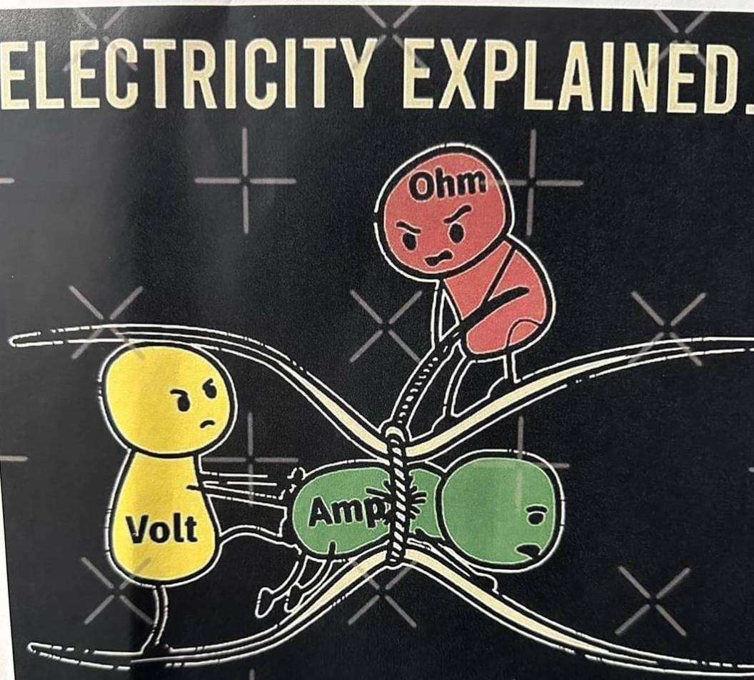
| A NOTE ABOUT RESISTORS
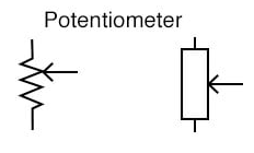
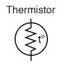
EFI works by Electricity. Electricity works in Volts, Amps, and Resistance. An EFI computer uses Volts, Amps, and Resistance to calculate Fuel. A Resistor resists electricity, kind of like a kink in a garden hose.
In EFI we typically have resistors that VARY their value based on temperature (Thermistor), or by movement (Potentiometer). A variable resistor typically has a set voltage feeding it on one side (usually 5Volts), a ground on the other (0V), and we tap into the middle somewhere to get a changeable in-between voltage out of the middle. Throttle Position Sensor (TPS): This provides the Acceleration Circuit of a carburetor. It tells the computer where your foot is, or what your foot is doing with the throttle. The computer will activate “Accel Enrichment” to squirt extra fuel when the throttle is opened quickly. It will also “Flood Clear” when your foot is on the floor while cranking – this will shut OFF the injectors!
Manifold Absolute Pressure (MAP): The MAP samples barometric pressure (air pressure) to know what altitude you are at, and (when the engine is running) tells the computer what the engine load is. Typically idle is around 30kPa, and full throttle will see 100kPa (KiloPascals – the unit of air pressure. Earth is typically 100kPa at sea level).
Low Vacuum = wide open throttle = high load = more fuel High Vacuum = closed throttle = low load = less fuel COOL TRICK, BRO: When you are slowing down (decelerating), EFI can see the HIGH ENGINE VACUUM and CLOSED THROTTLE and activate “Deceleration Fuel Cut Off” (DFCO), which shuts off fuel when you are decelerating, saving fuel! Carbs, on the other hand, see high vacuum and suck everything and the kitchen sink through the idle ports, going Pig Rich!
OBDI Troubleshooting (MAP Sensor) True Story!A student brought in a 1989 Mustang that had been heavily modified with an Edelbrock intake, headers, performance camshaft, dual exhaust, and other treats. I don’t know if anything had been done with the computer to make it happy. The student replaced the motor mounts (which were torn), and to do so, they jacked the motor up to get at the mounts. When they were done, the engine ran PIG rich, with black soot puking out the exhaust. It idled horribly, had no power, and wouldn’t rev. The ignition timing was also WAY far away from where it was supposed to be. We checked the computer’s codes, which said the EGR valve (exhaust gas recirculation valve – an emission control device that only works at cruise) was malfunctioning. You’d be quick to replace the EGR valve, wouldn’t you? Except there was no EGR valve on the motor – it had been removed and blocked off – so that couldn’t be the problem. Hmmm…… When is an engine PIG rich? At full throttle. What would the computer see at full throttle? Zero vacuum. Why would the computer blame EGR? If the EGR valve is stuck open at idle, there would be a large air leak into the exhaust. – and the old-school computer was too dumb to think it was anything else. It only knew to blame the EGR for any very low vacuum issue. What device tells the computer about engine vacuum? The Manifold Absolute Pressure Sensor (MAP) Sounds like the Manifold Absolute Pressure is faulty. Closer inspection showed the vacuum connection had been broken off of the sensor, so the computer thought the engine was full wide-open throttle at idle. Full-throttle means “go pig-rich” but full throttle (low vacuum) doesn’t make sense at idle, so blame the EGR valve. Fixed it, and it ran great! Mass Air Flow (MAF): Tells the computer how much air is flowing into the engine.
The MAF usually has at least three wires (but may have more).
High Flow = wide open throttle = high load = more fuel Low Flow = closed throttle = low load = less fuel
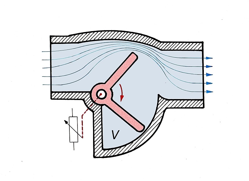
Another design uses an Air Vane, a “door” that moves further the more air is trying to get in.
The Air Vane MAF typically has three wires:
NOTE: Not all ECU’s use a MAF sensor. Some use a MAP sensor and IAT and use math to figure out the air flow (called “Speed Density” tuning).
Engine Coolant Temperature (ECT):
The ECT is a thermistor (a variable resistor that varies its resistance by TEMPERATURE). Different resistances will be understood by the computer as a different temperatures. The ECT typically has two wires:
Knowing the temperature of the engine is important, because a cold engine needs extra fuel to help it stay running while it is warming up.
The computer will go through “COLD START ENRICHMENT” to get the engine running, then progress through “WARM UP ENRICHMENT,” tapering off the additional fuel as the engine warms up.
Intake Air Temperature (IAT):
The IAT is a thermistor (a variable resistor that varies its resistance by TEMPERATURE). Different resistances will be understood by the computer as a different temperatures. The ECT typically has two wires:
Knowing the temperature of the air is important, because a cold day has denser air – there are more oxygen molecules per volume of air, and thus will require more fuel. A very hot day has less oxygen molecules, and requires less fuel.
OBDI Troubleshooting (Intake Air Temp Sensor) True Story!A student had a ’92 Geo Tracker that acted like it wasn’t getting fuel when it was hot outside. A problem the vehicle had with the original owner as well. There were no trouble codes. Testing revealed the Intake Air Temperature (IAT) sender was giving an incorrect resistance to the computer. The ECU believed that it was 160°F outside, and fueled accordingly. HOT air is expanded (less dense air), which has less oxygen molecules per volume, which needs less fuel.
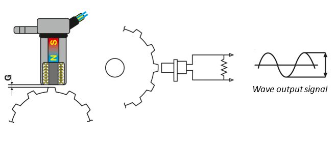
Crank Trigger: Tells the computer how fast the engine is running so the computer can “map” the correct amount of fuel. This is an Inductive Sensor that sends a voltage pulse to the computer. The crank trigger is usually a magnet wrapped in loops of wire. When a tooth on a wheel lines up with the magnet/loops-of-wire, a voltage pulse is created in the wires, which the computer can use to count RPM (Engine speed), or find Top Dead Center (TDC).
Crank Trigger sends a voltage pulse to the computer. The ECT typically has two wires:
Full throttle at 850rpm requires much less fuel than full throttle at 8500rpm. This is usually run off the ignition system, and there are many, many ways to do this.
Oxygen (O2) Sensor: OMG! ONE OF THE 7 WONDERS OF THE UNIVERSE! THIS is what makes EFI so freakin’ awesome! It tells the computer how well the engine is burning the fuel. The O2 sensor is an Electrochemical Sensor – it sends a varying voltage signal to the computer based on OXYGEN CONTENT in the exhaust. MAGIC. It GIVES voltage in the presence of OXYGEN. Freakin’ black magic and voodoo. The O2 typically has two wires:
Although the more expensive and better O2’s will have four wires:
The computer can use this input to “tweak” the fueling RICH or LEAN as needed, until it is burning the fuel properly.
Why it’s so awesome:Oxygen Sensor (O2): Gives feedback to the computer to let it know how it’s doing. Produces a voltage based on the level of Oxygen in the exhaust (0 to 1V. 0.5Volts is Stoichiometric. The higher the voltage, the richer the mixture is). With an O2 sensor, the engine is tuned as it drives, tailors itself to the way YOU drive, adjusts itself for wear, tear, altitude, temperature, everything!
When the ECU looks at the O2 sensor to see how it’s doing and adjusts itself accordingly, that’s called Closed Loop. Often Idle and Full Throttle are Open Loop (that is: NOT referencing the O2 sensor). Without the O2 sensor, the fuel system is just guessing. Now the computer can always look to see “How am I doing?” If it needs more fuel, it just increases the injector pulse width by leaving the injector open a bit longer. It’s kind of like looking at your poop and saying “I need to chew my food more” or “I don’t remember eating that.” — It’s FEEDBACK!
OBD II (Oxygen Sensor) True StoryFor a time, my kid’s ’03 Honda Civic was running like crap when he drove it to work. It had absolutely zero power and was basically undriveable. If I did a super-fast pulse on the gas pedal, I could drive it into the shop. No “Check Engine Light,” no codes, so whatever it was doing was either “OK” by the computer, or not monitored by the computer. The scan tool showed the O2 sensor reading 0.9V (PIG rich), and the computer was pulling 35% fuel out of the tune to correct it, yet the engine was VERY DEFINITELY super lean. We replaced the O2 sensor and what the computer was seeing made sense again. $75.
Fuel Injectors are PULSED to control their OUTPUT (how much fuel you get):
Fuel Injector Pulse Width is how the ECU controls the amount of fuel. Like playing a driving game with only the keyboard, you control how much you turn left by “pulsing” the arrow key. Same deal for controlling fuel flow – injectors are either ON or OFF, so you need to pulse them.
With the chart below, you can see what’s going on in an engine, and what your target Air Fuel Ratio (AFR) should be. With the appropriate sensors, we just tell the computer what’s going on. The Computer watches the O2 sensor, makes adjustments, then watches the O2 sensor again. This is called “CLOSED LOOP”. However, when an engine is warming up, and when an engine is operating at WOT, the ECU resorts to base mapping and does not look at the O2 sensor – this is called “OPEN LOOP.”
Yes, you can put an O2 sensor on a carb’d vehicle; then you can tune the carb to perfection (by changing jets) instead of just guesswork!
|
||||||||||||||||||||||||||||||||||||||||||
EFI TUNING |
||||||||||||||||||||||||||||||||||||||||||
| We mentioned above that the engine TUNES itself as it runs, by looking at the Oxygen (O2) Sensor and making adjustments. Let’s talk about that.
When the Computer is initially programmed, it has a BASE MAP that the Engineers have created and tested to be pretty much what the engine is going to be most happy with. Except not every engine is exactly the same, despite being built exactly the same; there will always need to be some adjustments. IMMEDIATE TUNINGWhen the engine is first started, the Computer will QUICKLY begin adjusting and optimizing its fueling for perfect combustion (to minimize pollutants). It needs to do this “right now,” and make quick, “knee-jerk” adjustments to the tune. In Computer Speak, these are Short Term Fuel Trims (STFT), kind of the ADHD of fuel adjustments. You can even watch these on a scan tool. They will go rich-lean-rich-lean as the engine is running, as the Computer tries to “zero in” on perfection (but does so by overshooting and “averaging”). You can actually watch this happening on the can tool! Typically, I expect to see +/- 5% correction in STFT. LONG TERM TUNINGOVER TIME, as the computer sees the engine’s TENDENCY to be rich or lean, it will make more “permanent” corrections into the tune. This is stored in the Computer’s MEMORY, and every time the engine starts, it begins with an already “tuned” starting point for what the engine wants. In Computer Speak, these are Long Term Fuel Trims. These give me an idea of how happy the fuel system is – corrections +/-5% are nothing to worry about. If the engine is really tired, or there is a problem in the intake system or the fuel system, I would see some significant corrections going on here. When an engine is seeing +/- 10% or 15% or more fuel correction, I want to investigate.
EXCITINGLY, since these are stored in the computer’s MEMORY, when you disconnect the battery or the battery goes right dead, it “forgets” its tune, and it may take a little while to figure itself out again. It may run a bit different while it’s doing that, but it WILL re-tune itself. On my turbocharged 1961 Chevy pickup, I DISABLED Long Term Fuel Trim, because I don’t want it to be tuning itself “lean” for whatever reason, and then carry that lean “tune” into BOOST. If a turbocharged engine does not have enough fuel to eat, it will eat pistons. TUNING AND OUR NEXT UNIT:In our next unit, we will talk about Spark Timing, where again the Computer can “untune” your engine if it’s sensing issues with combustion inside the engine. If your car is designed for High Octane gas, and you’re running Low Octane gas, your Computer will “untune” the engine for its survival. This will cost you both power and fuel economy (but will it be offset by the savings in fuel cost? I don’t know). Interesting Video (Steve Morris Engines) and not on the quiz: Low Octane Fuel Makes MORE Power!
|
||||||||||||||||||||||||||||||||||||||||||
EFI Basic Components: |
||||||||||||||||||||||||||||||||||||||||||
| Throttle Body:
Simply a block with a throttle plate in it to control air flow. There is no restrictive venturi. In the TB pictured, you can see the TPS connector on the far left. On the back side, you can see another electrical connector – this is likely an Idle Air Controller – a device which allows the computer to control idle speed. Many modern vehicles now control the actual throttle by the ECU – you aren’t actually opening it directly! This allows a computer to “filter out” your “operator error” and give you what it thinks you want. I like it, and don’t like it, at the same time.
Fuel Injector: Very precise fuel “squirter” – the computer decides how long the injector is open for. They require a consistent and regulated fuel pressure. There may be one or two injectors mounted in the throttle body itself (“Throttle Body Injection”), or one per cylinder at the intake port of the head (Multi-Point Fuel Injection). Injectors open to flow fuel when they are turned ON by the Computer. To VARY the amount of fuel, the injectors can be turned ON and OFF at different rates. If the time the injector is ON is very small, little fuel can flow out. If the time the injector is ON is very large, lots of fuel can flow out. This “ON TIME” is called PULSE WIDTH. Pulse Width is like playing a driving game with just the keyboard – you can’t just hold the arrow key down to steer, you need to “pulse it” on and off and on and off to make the size of the turn you need.
Electronic Control Unit (ECU): The computer. It takes all the sensory inputs, calculates what kind of fuel the engine should get, and pulses the fuel injectors accordingly. EFI computers “tune” themselves as you drive, and store the current “tune” in memory. If you disconnect the battery, the computer will forget everything and return to the original assembly line tune, which might run like crap if your engine is not “brand new” and the ECU has to “retune” itself. Most computers can re-tune themselves within a drive or two. Also called PCM (Powertrain Control Module) or ECM (Engine Control Module).
Fuel Pump: In order to inject fuel effectively, the fuel system must be pressurized much higher than a carbureted system. While carbs need about 3-7psi fuel pressure, most EFI systems run around 30-75psi. In-tank pumps are the most common, and they usually cost up to $900 to replace. Want them to last longer? Change your fuel filter EVERY year, twice a year if you can swing it (except most cars now don’t have replaceable filters, the filter is on the pump. You just run it until the pump cacks, then replace it). Many modern vehicles DO NOT have a replaceable Fuel Filter – you replace it when you inevitably burn out the fuel pump. I replace fuel pumps at the “10 year” mark – it’s convenient in my shop on a weekend, it’s inconvenient at the top of the Coquihalla in the dead of winter.
Fuel Pressure Regulator: Fuel injectors have a certain range of fuel they can flow. A really large injector might not be able to pulse slow enough to run lean enough at idle, and an injector that can run slow enough at idle might not flow enough for full throttle. We can improve this by using a pressure regulator that references engine vacuum, so at high vacuum (idle and cruise) the fuel pressure is reduced to make it easier to “tune” at idle, and at low vacuum (WOT) the fuel pressure is increased so more fuel can be delivered.
OBD II (Fuel Pressure Regulator) True Story Bro:For a time, my kid’s ’03 Honda Civic was running like crap when he drove it to work. It ran fine at full throttle but nothing else. No “Check Engine Light,” no codes, so whatever it was doing was either “OK” by the computer or not monitored by the computer. I could not duplicate the “crappy” running myself. In the end, it was the Fuel Pressure Regulator (FPR) sticking on “Full Fuel Pressure,” and the computer couldn’t un-tune that to work properly, it just ran pig rich. New FPR and it was fine afterward.
The Computer looks at all the sensors, does math, and decides how much fuel to give. To help it decide quickly, the computer was given a “map” to start from – the fueling we expect it will likely need, plus any corrections the math decided it needed to do. This “Fuel Map” is what tuners mess with to get more power out of your vehicle.
Prepare for your head to explode!
|
||||||||||||||||||||||||||||||||||||||||||
On Board Diagnostics (OBD) |
||||||||||||||||||||||||||||||||||||||||||
| Early EFI
Early fuel injection computers were very simple programs. They took inputs, they gave outputs. If an input went outside of its expected range, math happened anyway. If the ECT said it was -500° outside, the computer crunched the numbers and fueled the engine accordingly. Good luck with that (Lean City!). Those old computers were pretty dumb; you really had to understand what was going on in order to find the cause of the problem/ My Lotus Super 7 replica (I soldered my own computer together from a kit) has ZERO diagnostic ability whatsoever. Zero. You get what it gives you, even if the math is drunk. If it thinks it’s 7000° outside, it will happily fuel accordingly. ….Steel melts at 6000°
OBD-I By the late ’80’s many manufacturers had their own method of interacting with the ECU – you might jumper two connections with a paperclip, you might turn a screw back and forth, you might turn the key on and off three times, everybody had their own way of dealing with it – you had to remember a LOT back then (you still do today!!). There were unique ports you could measure voltages and resistances from, or plug in a diagnostics computer and read what was going on inside, or count the number of flashes on a blinking light. Most computers could now recognize if a sensor was faulty and let the driver know there was a problem. If the IAT sensor said it was -500° outside, the computer would recognize that’s not a typical Earth Temperature, turn an MIL on the dashboard, and it might pick a “safe” number to run with (it might “assume” a temperature of 22°C outside even if it isn’t). A mechanic could then plug into the computer and the computer will give the mechanic a “Trouble Code” which would tell him what the ECU thought the problem was (what the ECU thought the problem was, not what the problem IS).
Any sensor running outside its expected range will throw a trouble codeIf your engine is having a driveability problem, and there are no codes, that usually means the cause is something that the computer isn’t monitoring
What was annoying back then, was that every manufacture did this differently. This meant you had to have different test equipment for every vehicle you ever saw.
OBD-II 1996+ Today’s vehicles are all standardized with OBD-II, and have been since 1996. The computers all use a common diagnostics connector (called a Port, usually under the dash by the driver’s knees), and the computers all used the same codes. The Diagnostic ability of the computers are much more advanced, and very helpful in pinpointing problems.
Today the ECU also checks to make sure all emission controls are working correctly, and will throw trouble codes if anything isn’t right. Like the gas cap is missing, for instance. Or cylinder #3 is misfiring.
My first code reader at home is a cheap Chinese eBay purchase that can read codes and show data. It was totally worth the $35 I spent on it. My latest code reader was $500 and is bi-directional – that means I can control things on the car from the scan tool – VERY useful in finding the cause of problems. The school’s latest scan tool is around $2000 and can do more than I fully understand.
OBDI Troubleshooting/Hacking – True Story!I put very oversized and free-flowing exhaust pipes and straight-through muffler on one of the trucks I owned. The increased exhaust flow really improved performance above 4000rpm, but the increased air flow also increased fuel consumption (more air going through needs more fuel to feed it). The truck made it to the parking lot before the Malfunction Indicator Lamp (MIL, “Check Engine Light”) lit. The computer code said that the EGR (Exhaust Gas Recirculation valve – an emission control device) was faulty. The computer did not know that I had changed the exhaust system. It expected to see a temperature increase in the intake manifold when the EGR valve was open (that’s how it knows the EGR valve is working). But the exhaust system was so wide-open, there was no heat increase. The Factory Service Manual (FSM) told me that the computer was looking to see 10K Ohms at an intake temperature sensor (a Thermistor). So I unplugged the actual sensor, and plugged in a 10K resistor. Now when the computer looked for a temperature (resistance value), it “saw” that wanted resistance value, and was happy and the light stayed off. Kind of like snapping a picture of the empty room and putting it in front of the security camera so nobody saw that you all were having a party. The downside – if there actually ever WAS a problem with the EGR system, it would never ever know and never ever ell me.
OBDII Troubleshooting – True Story!OBDII is a much smarter computer. They arrived in 1996. Pops had a Toyota Tundra. The MIL light is on. Reading the codes says there is a problem on the right-side oxygen sensor. When I looked at the live data while the engine is running, the readings indicate that O2 sensor always sees “lean” (different than what the left-side O2 sensor is reading). It could be that the right-side O2 sensor was faulty……. But there was a crack in the right-side exhaust manifold that allows extra air to get into the exhaust stream, making it seem lean. The proper fix was to replace the cracked exhaust manifold, but since Pop’s truck was SUPER rusty, we were sure some of the manifold bolts were going to shear off, making the repair a whole world of hurt. He’d already been quoted $2000 from a shop to fix it, and I DID NOT want to deal with broken exhaust bolts (I know “not fun” when I see it). So…. we ignored it. (grin).
|
||||||||||||||||||||||||||||||||||||||||||
SERVICING |
||||||||||||||||||||||||||||||||||||||||||
|
Because of Fuel Injection, there is no “tune up.” In fact, there is very little that you need to do to maintain the fuel system these days, just replace the plugs and filters on a regular basis and you’re good. Some mechanics suggest running a fuel injector cleaner through the system once a year. Some don’t. Some cleaners are better than others. This could fall under “snake oil, black magic and voodoo.” I have not found huge (if any) improvements using it.
Replacing the Fuel FilterFuel Filters should be replaced once a year. It has been said that Okanagan fuel is quite dirty, and filters should probably be replaced twice a year. A plugged fuel filter will reduce power, and burn out an electric fuel pump (you’re not going to actually find that last sentence for the question in your booklet – point THIS sentence out for a free bonus mark). Expect to spend close to $1000 to have a fuel pump replaced for you. Many manufacturers no longer have a replaceable fuel filter. You just drive it until it kills the pump, then buy a new pump. I have no idea why they do it this way now. Probably cost-savings.
Replacing the Air FilterAir Filters should be replaced once a year, more frequently if the vehicle is used in a very dusty environment.
Replacing the Fuel PumpWhen I buy a new-to-me vehicle, I go through full servicing, including replacing the fuel pump! Replacing a fuel pump is convenient in my shop on a weekend. It is less convenient at the top of the Coquihalla in the dead of winter. Every single car fuel injected car I have ever owned had its pump die at an inconvenient time.
Replacing an Oxygen SensorCleaning Injectors In PlaceOver time, especially with limited use, injectors can get debris in them, and they may not flow enough fuel. If (with a Code Reader that can show Data Stream) the Short Term Fuel Trim (STFT) is showing some significant added fuel (like maybe 15% more?), you could try cleaning the injectors. This method involves disconnecting the fuel feed to the injectors, and running the engine on some creative elixir:
Cleaning and Flow Testing InjectorsThis method involves physically removing the injectors, ultrasonically cleaning them in a debris-softening elixir, flushing them, and then flow checking them. This is arguably the better way to go, since you actually see the flow pattern, and can actually confirm the volume they flow:
For more information: http://www.innerauto.com/Automotive_Systems/Fuel_System/ |
||||||||||||||||||||||||||||||||||||||||||
INTERESTING ARTICLES: |
||||||||||||||||||||||||||||||||||||||||||
NONE OF THESE ARE ON THE TESTBut interesting nonetheless… This modification is not typical: “Decapping” GM injectors for more flow! |