
[The Engine] [Cylinder Heads] [Engine Blocks] [Fuel System] [Ignition System] [Cooling System]
Click to Print – QUESTION SHEET |
|||
HISTORY |
|||
|
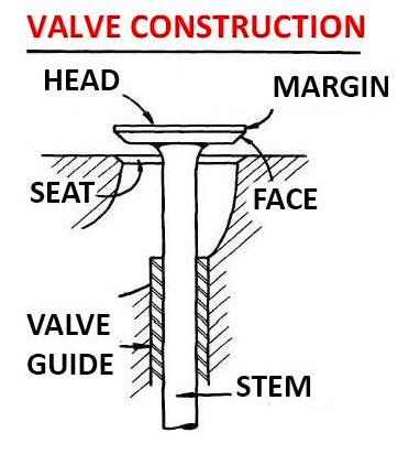
The cylinder heads sit on the top of the cylinder block.
The top part of the cylinder block contains the piston, and the bottom part of the cylinder block contains the crankshaft. Originally the cylinder head was merely a plate bolted to the top the engine block, and provided the spark plug and combustion chamber. The camshaft, valves and valve ports were located in the engine block. This was easy for the engine to lubricate with oil (oil splashed up from the connecting rods), but it wasn’t good for air flow or engine power – the air had to go through a number of tight bends on the way into the cylinder, and then a number of tight bends to get out of the cylinder. Since the head itself was flat, this engine design was called a “Flathead.” Ford was the hot rodder’s choice for YEARS when it released the Flathead V8 in 1932. Chevrolet didn’t have a V8 until 1955 (and then Chevy’s engine was tops).
One of the Ford flathead’s design problems was overheating. Serious overheating. Because the valves were in the block, and because the exhaust valve was on the inside “V” of the block, the hot exhaust gasses had to go THROUGH the water jackets surrounding the cylinders to exit the block. This put a great deal of heat into the coolant. Ford Flatheads had TWO water pumps to try and keep the motor cool.
The flathead, or “L-head” engine, still remains in lawnmower power plants. Both the Tecumseh and Briggs and Stratton are good old 1930 technology “L-head ” engines.
A letter Clyde Barrows wrote to Henry Ford thanking him for the V8 in the 1932 Ford, and praised its high speed ability.
Clyde was part of the bank-robbing duo “Bonnie & Clyde” during the great depression, and were eventually ambushed and violently shot to death in 1934. Bonnie & Clyde were instrumental in making the Police Force what it is today.
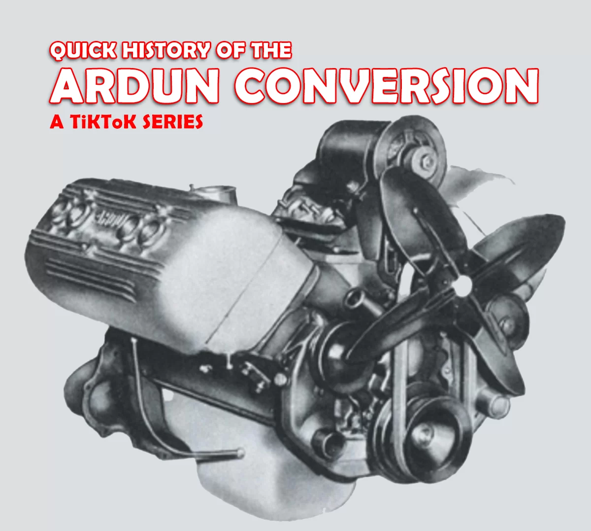
Improving on the FlatheadChanging the Flathead’s (valve-in-block) poor-flowing ports to have a more direct flow into the cylinder meant moving the valves and ports to above the cylinder and into the head. This meant either running pushrods off the camshaft up to rocker arms on the top of the head, or move the camshaft up to the head (run off a long belt or chain) and operate the valves up there. Below is an Over-Head-Valve conversion for the old Flathead designed by Zora Arkus-Duntov (he became the Father of the Corvette at GM). This turned Ford’s L-Head/Flathead/Valve-In-Block engine into a Hemi. Notice the MASSIVE cylinder heads and valve covers! “ARDUN” is an abbreviated “Arkus-Duntov”
Below is a cutaway – can you see the original (in-block) intake port (no longer being used) underneath the new intake port in the Intake Manifold? VIDEO: How an Ardun OHV Conversion Works
Almost all engines made today now come with two camshafts (one for intake, one for exhaust) on top of the head, running the valves directly (no rocker arms), with nice straight ports flowing right into the cylinder.
The cylinder head is the part of the engine that produces the most power. Engine builders spend a lot of time and money developing and modifying cylinder heads to make power. The heads are the ticket to power. There are many, many different types of cylinder heads and valve arrangements. Their basic operation is the same; they tend to all use the same parts. They all wear out the same. They are all rebuilt the same. |
|||
COMPONENTS |
|||
|
The cylinder head itself is usually cast out of either iron or aluminum (yes, or Magnesium, you Porsche/VW fanatics….). Any surface that must be sealed or attached to something will be machined perfectly flat for the best seal. The head will contain:
Valves – open and close allowing air and fuel in, and exhaust out. The valve stem fits in the valve guide. The valve face seals against the valve seat. The valve tip rides against the rocker arm. Valve Guides – Iron, steel, or bronze passages, that hold the valve stem in precise location. The valve guide is the REFERENCE for the valves to seal Valve Seats – Iron, steel, or Stellite rings that the valves seal against, usually part of or pressed into the head. The face of the valve seals against the valve seat in the head.
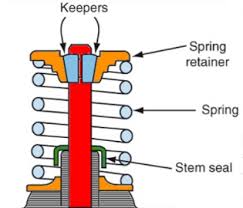
Interesting but not need-to-know: Beryllium-Copper seats must be used with Titanium valves. Titanium is really only used for racing. Valve Springs – These close the valves, when the camshaft is done opening them. Aluminum heads ALWAYS use a spring shim or washer under the spring to protect the aluminum (otherwise your engine oil becomes sparkly bass-boat goodness). If you rev your engine higher than it is intended to go, these may not close the valves fast enough, dramatically killing your power (this is called “valve float;” mother-nature’s “rev-limiter”). Valve Retainers – Looks sort of like a washer on top of the valve spring, it holds the spring and valve in place in the cylinder head, held in place with wedge-shaped “valve keepers” Valve Keepers – Semi-circle shaped “wedge” locks that fit into a groove in the valve and keep the retainer and valve spring in place on the head. Valve Seals – Rubber or Viton seals prevents oil from being sucked into the engine through the small gap between the valve stem and the valve guide. Oil drawn in through valve guides past the seals results in BLUE smoke in the exhaust, especially when off-throttle going downhill (high vacuum in the engine) – common in worn engines.
Combustion Chamber – A “cavity” shape cast into the cylinder head that houses the valves and the spark plug. There are many different shapes (such as L-Head, Wedge Head, Hemi-Head, Polyspheric Head, Pent-Roof Head…), each with their own advantage and disadvantage.
Power and economy magic can happen with a good chamber design. Your favourite muscle car from the 60’s had a garbage combustion chamber design. Sorry.
Depending on the engine design, the head may also contain: Rocker Arms – Used to change the motion direction, such as in an Over-Head Valve (OHV) engine to go upwards from the camshaft in the block, to change direction and operate the valves downward above the cylinder. 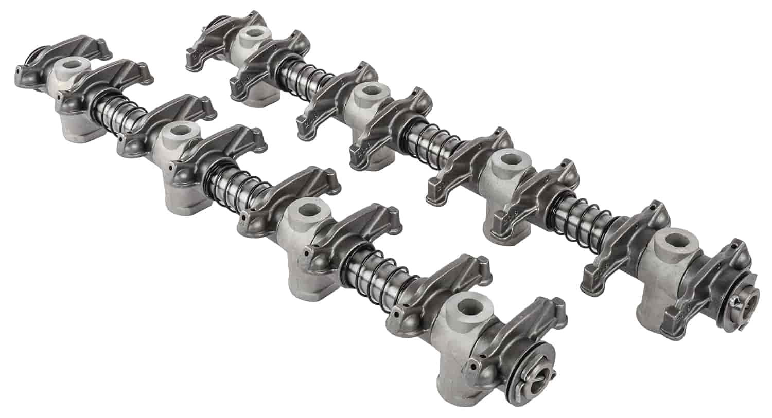
Camshaft – This is a shaft with eccentric lobes (cam lobes) that are very accurately machined for exact opening and closing points of the valves. It rotates at HALF engine speed (the piston needs to do its thing twice, while the valve only need to once).
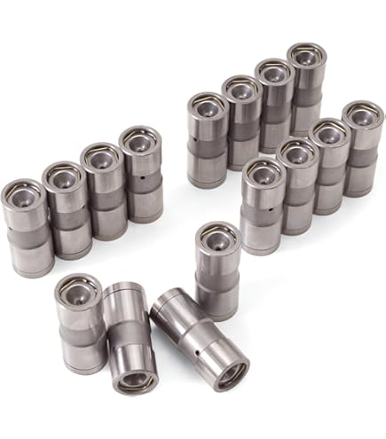
The camshaft is the “personality” of the engine. You can optimize an engine’s power to work in a truck, car, hot rod, or racecar, just by picking an appropriately sized camshaft. Lifters – These are little cylinders that ride on the cam lobes. It is common today to use a hydraulic piston inside them to make them continuously self-adjusting. Once a lifter is “broken in” to its specific cam lobe, they are “married” to each other – they CANNOT be swapped around or they will DESTORY each other, and all that wiped metal goes everywhere inside your engine!
Typical OHV (Over Head Valve) – notice the rocker arms (camshaft is in the block):
Typical SOHC (Single Over Head Cam) – notice the rocker arms (camshaft is under the rocker arms), which have a threaded adjuster and lock nut to adjust valve clearance:
Typical DOHC (Dual Over Head Cam) – no need for rocker arms, the cam acts directly on the valve (with a bucket shim to adjust clearance:
|
|||
DISASSEMBLY |
|||
|
Here you must be sure to keep track of everything. Most students do not pay attention during the disassembly and lose many of the parts vital to the life of the head. KEEP TRACK OF EVERYTHING!Take pictures! Take notes! Label parts! Store in containers! Consult the service manual to see how things are disassembled – they will show you the correct procedure. Some tricks I use to help me rebuild heads: Write the cylinder number on each valve as you remove and clean it – every valve belongs to its guide, don’t mix-and-match them. Store the valves in order, as they appear in the head, with the stems punched into a piece of cardboard. This keeps them together and in order. String the rocker arms (and their pivot balls if equipped), in order, on a length of wire. This keeps them together and in order. Thread fasteners back into their holes so you know where they came from Pictures are worth a thousand words – take lots of them.
Machined surfaces of the head, valvetrain and camshaft are very fragile – protect them from damage at all costs. You have no idea how expensive these parts can get, individually. Once the head is completely disassembled, cleaning can begin.
|
|||
CLEANING |
|||
|
The cylinder head must be white-glove clean. You do not want any dirt or crud inside your freshly rebuilt engine. Heads can be cleaned by most machine shops using a caustic solution. It will be thoroughly cleaned, and all grease and paint will be stripped off. I always clean parts again by hand just prior to assembly just to make absolutely sure they are clean – I do not trust anybody, only myself. Valves can be easily cleaned using a WIRE WHEEL on a bench grinder. Carbon and crud cakes onto the valves when the engine is in use – a Wire Wheel is often the only way to get it off. Oven Cleaner is also a great engine cleaner – it dissolves Carbon. YOU are a carbon-based life form, so wear eye protection, skin protection, and lung protection.
  Once the head and all the parts are thoroughly clean, we can inspect, measure and rebuild the head.
|
|||
INSPECTING CYLINDER HEADS |
|||
|
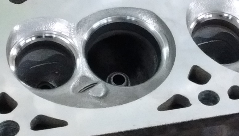
I tackle heads in this order: #1 – MUST HAVE NO CRACKS (if it’s cracked, get another head) #2 – FIX THE GUIDES (valve seats cutters reference the valve guides) #3 – FIX THE SEATS & VALVES Inspect all surfaces for cracks, especially inside the combustion chamber as well as between the valve seats. A machine shop will use Magnafluxing or special dies to find ANY and ALL cracks – worth the money if any parts are suspect). You want to look for cracks first, as a cracked head is a worthless head, although valuable heads can have the cracks welded up (it just costs money).
 Cracked head shown with a special die and blacklight.
NOTE: Cracks can be fixed by various forms of welding, but you have to decide if the cost is worth it. For a 1932 Duesenberg, yes. For a 1988 C1500, no. Inspect all valve seats for wear, burning, cracks, gouges, pitting or damage. Damaged valve seats can be re-machined to perfection, or cut out and new ones pressed in if it’s really bad.
Measure the head surface for warpage using a flat feeler gauge and a Straight Edge. Warpage means the head must be milled flat, although anything 0.002″ or less (about the thickness of your hair) on an aluminum head, or 0.004″ or less on an iron head is considered “OK” Warping usually indicates an engine that has been overheated. Overheated engines usually cook the pistons rings as well. Overheated engines are usually NEVER the same again.
Measure valve guide clearance using a dial indicator and a stand, with the valve sticking out of the valve guide only as far as the valve is normally opened (look at the wear on the valve stem. If there is too much wear, either the valve guide or valve stem is worn or both. If the guides are worn they can be replaced, knurled and reamed, or fitted with a bronze insert.
|
|||
INSPECTING VALVES |
|||
|
Inspect all valve faces and valve tips and rocker arms for any wear, pitting, gouges, burning or any other damage. Wear is a reality, but it should always look very smooth and uniform. Valve faces and seats can be re-machined to perfection, however as metal is machined away the valve will sit further and further into the head making the valve tip sit higher, and the valve spring be compressed less. The valve tip is then machined to keep the valve clearances correct, and shims are placed under the valve spring so the valve is compressed the correct amount.
Measure the valve stem for the greatest wear. If the valve stems are within spec, they can usually be reused. The faces and tips get machined.
Zero PSI Compression?A student had a Mazda 3 that ran rough and had a “misfire cylinder #2” error code. The spark plug was disastrously fouled. Compression test gave Zero PSI in cylinder #2. Leak Down Test had 100% leakage in cylinder #2, and as you rotated the engine, air leaking INTO cylinder 1, and then INTO cylinder 3, and then INTO cylinder 4. That can only happen if there is a burned valve, and usually exhaust valves are the ones that burn. Oh look:
|
|||
REPAIRING VALVE GUIDES |
|||
|
The valve guides should be taken care of FIRST; the valve seat is machined using the guide as a REFERENCE, so the guide better be good. There are a couple of options in repairing the valve guides: Knurling: This runs a special die through the inside of the guide to deform the hole smaller. The guide is then reamed to the required size. It produces a sort of “threaded” finish on the inside. Some say the threaded finish is good, because it helps contain some oil so the guide is better lubricated, thus lasting longer. Others say the threaded finish is bad, because there is less metal contacting the valve, and it will wear quicker.
Bronze Inserts: This requires reaming the guide larger, and pressing a thin bronze sleeve into the guide, and then the newly-inserted guide is reamed to the required size. It produces a sort of “bushing” finish on the inside. Some say the bronze insert is good, because it is a softer material and acts as a better bushing material than steel. Others say the bronze insert is bad, because there is a chance the insert could come out, and since it is a softer material it will wear quicker.
New Steel Inserts: This requires machining the entire valve guide out of the head, and a new steel guide pressed into place. Some say the steel insert is good, because it is now just like it was intended from the factory. Others say the pressure from such a large object being pressed into the head may distort the entire cylinder head possibly resulting in leaks.
GRRRRR! I took a set of heads to a local machine shop, asked them to replace the guides, cut the seats, and mill the heads. I had measured the guides and there was too much clearance. When I went to pick up the heads, they had milled them and cut the seats, but did NOT do the guides – they laughed and said “we didn’t even measure them, we wiggled them, they’re mint!” Idiots. I can’t see how you can wiggle something and be able to “feel” 0.0015″ over spec. The hair on my head is 0.0015″. And the kicker is they cut the seats, which reference the guides, and the guides are loose. AND they cut the seats so deep that I had to re-shape the combustion chambers to remove a hefty power-killing ridge they left around the valve seat. I am not a happy camper.
|
|||
REPAIRING VALVE SEATS |
|||
|
The valve seats are machined nice and smooth again using a a valve seat cutter. Seats and valves are usually cut at an interference angle – the valve seat is typically cut at 45°, and the valve face is cut at 44°. This provides a fairly narrow contact area, improving sealing. The best valve job uses three angles and is often called a “3-angle valve job.” Even more angles can make more power. They say the majority of the cylinder head performance is the shape around the valve seats. When machining, only enough material to clean the seat up. As the valve seat is machined down, the seat gets wider. Too wide a seat might not seal; too narrow a seat might burn. The next cut is a 30° (often called a “top cut”) which improves the air-flow from the valve seat to the chamber, AND narrows the top of the seat cut – the seat contact needs to be 1/3 of the way up from the margin. The final cut is a 60° (often called a “throat cut”) which improves the air flow from the valve seat to the port, AND narrows the width of the seat cut. More performance can be had by adding 15° top and 80° throat cuts. ALL your engine performance can be MADE or BROKEN by how you deal with the valve seats!
As the valve seat is machined, the valve sinks into the head. This means the valve tip will stick up too high, and it must be ground down. Also the valve spring will not be compressed enough, so it must be shimmed.
|
|||
REPAIRING VALVES |
|||
|
The valve face is machined nice and smooth again using a Valve Grinder. The key is to take off only enough material to clean the valve up. As the valve face is machined down, the margin (the 90° edge of the valve) of the valve gets smaller. The margin that is too small will easily burn, ruining the valve.
  As the valve face is machined, the valve sinks into the head. Cutting seats, too, sinks the valves into the head. This means the valve tip will stick up too high, and it must be ground down. Also the valve spring will be compressed less, so it must be shimmed back up to the correct compressed height.
And now for something completely different:Lapping Valves The poor boy valve job. Uses a suction-cup-on-a-stick (or rubber hose on a drill), and sandpaper-in-a-paste. Some say you should always lap valves, even after properly cutting them, because it helps them seal better. Others say if you’ve properly cut the valves, why would you do anything so hokey as to lap them?
WHY ARE VALVES CUT AT 45°? Good question. You can certainly cut them at different angles. Shallower Seat Angles (less than 45°) flow well at low lift (not high lift) and may not seal as well (especially over time). They do tend to be more common in the Diesel world. Steeper Seat Angles (greater than 45°) flow a lot better but put a more stress on the face/seat and may begin to distort or “tulip” the valve, sinking the valve into the head over time. This is more commonly done on race engines where it is more important to win than it is to last.
|
|||
REASSEMBLY |
|||
|
The cylinder head should be thoroughly cleaned one last time. This includes running a tap through all threaded holes so that all the fasteners will engage properly and give accurate torque readings. Rust is your enemy, especially on iron heads. Once you’ve finished cleaning the head, blow it thoroughly dry with compressed air, and coat it with oil to prevent it from rusting. Some people like to paint the head before putting it on the engine, you can certainly do that at this time.
EVERY moving part is to be thoroughly coated with oil. I use a large tin can full of fresh oil to dip the entire part in oil. Yes, it will burn oil when I first start it up, but I know oil will be there right away. Camshafts need special Molybdenum-Disulphide-rich lubricant to ensure that the cam lobes are not wiped flat due to the extreme pressure and lack of lubrication. If you are using a new camshaft, use their recommended lubrication.
NO MOVING PART is EVER assembled dry!
CAMSHAFT LUBEAdequate and proper oil is REQUIRED for a flat-tappet camshaft to last. Due to environmental requirements, the main ingredient in engine oils that helps camshafts survive the sliding-friction of flat tappets – Zinc – has been reduced considerably. This is causing flat-tappet cams to wear out in a matter of kilometers or even minutes. If you want your classic muscle car or recently rebuilt engine to last, READ THIS: ARTICLE – PM Zinc Oil Additives
I strongly recommend running a high-zinc “break in” additive when running flat-tappet cams!
ALWAYS use new valve seals. Be careful not to nick the new valve seal with the valve stem on assembly.
ALWAYS use new gaskets. Gasket surfaces must be completely flat and completely clean. NEVER reuse old gaskets. If you’re working on something ancient, you can make your own gaskets using raw gasket material. I am not a big believer of silicone. There is a place for it (like the corners of the intake manifold on a “V” engine) but generally I prefer real gaskets over “gasket in a tube.” If you choose to use Silicone, use only enough to get the job done. Too much silicone gets squeezed out – I’ve found beads of silicone stuck in oil passages, floating around the engine, plugging cooling passages. Nasty.
ALWAYS torque all critical fasteners to the manufacturer’s specs and in the recommended order – READ THE MANUAL. A fastener under-tightened does not clamp the gasket enough to secure the gasket – it will fail, or the faster will fall out and the gasket will fail. A fastener over-tightened stretches, and loses its ability to secure the gasket – it will fail, or the fastener will snap and the gasket will fail.
ALWAYS use a new head gasket to attach the Cylinder Head to the Block. Head Bolts need perfect threads (you ~did~ tap the holes, right?), and to be torqued in STAGES, in a SPIRAL pattern starting from the CENTER out.
Adjust the valve clearances (lash) to the manufacturer’s specs – READ THE MANUAL. Clearances set too loose will be noisy (you will hear the clatter), and reduce power (the valves won’t open all the way). Clearances set too tight will hold the valve open, reduce power and burn valves.
If the head is not going back on a motor right away, wrap it in a plastic bag to keep moisture and dust out of it and keep it safe. Clean clean clean. I’m always surprised how students couldn’t be bothered to keep crud out of their brand new engine – like it’s too much work to get a garbage bag. I don’t understand it.
|