
[The Engine] [Cylinder Heads] [Engine Blocks] [Fuel System] [Ignition System] [Cooling System]
Click to Print – QUESTION SHEETBooklet Updated Jan 2026 |
|
The IGNITION SYSTEM is THE part of an engine’s TUNE that benefits you most for POWER and FUEL ECONOMY.
Things we’re going to look at:
Before we begin, we’re going to start with 1890’s technology. Don’t be afraid.
MR.WELLWOOD’S CLASSROOM LESSON:“Pickle Theory”
|
PURPOSE |
THE PURPOSE OF THE IGINITION SYSTEM IS ONLY TO IGNITE THE AIR/FUEL MIXTURE AT THE CORRECT TIME FOR MAXIMUM POWER AND/OR FUEL ECONOMYIt does not START the car, it merely FIRES the spark plugs. You actually need a LOT of voltage to ignite a highly compressed air/fuel mixture – MUCH more than 12V. More than 12V? Wait a minute!A car battery only provides 12V, but 12V isn’t enough to jump a spark plug gap? Yes. If you’ve ever licked a 9V battery and if you’ve ever been shocked by a spark plug, you know there is no comparison. A spark plug requires 5,000 to 15,000 Volts to fire. We need to produce this voltage, but how? We can TRANSFORM the battery voltage to something bigger – for that we will need a TRANSFORMER. You likely have these even at home for your electronic devices – those wee boxes that plug into the wall TRANSFORM the 120Volt wall voltage DOWN to something useable. But we can transform it UP, too! How does a transformer work? It’s super simple really, but first…. some History: At about the same time, Michael Faraday (UK, 1932) and Joseph Henry (USA, 1931) both discovered Electro-Magnetic Induction: MOVING a MAGNET past a COIL of wire would INDUCE (create) an electric current. The strength of the electrical current depends on the strength of the magnetic field, the size and number of loops of the coil, and speed of the motion. These four are related:
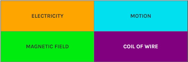
The Square of Electrical Fun:
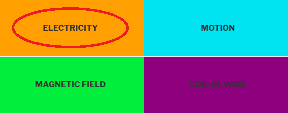
Cover the square you want (for example ELECTRICITY), and you need the other three to make it happen. If we MOVE 12V through a primary COIL of wire, we could INDUCE a magnetic field around the wire.
If we MOVE that magnetic field past a secondary COIL of wire, we can INDUCE voltage through that coil.
If that second COIL has a significantly greater number of coils than the first, the INDUCED voltage would be significantly greater. Thus, 9V through one coil could induce in the second the 15,000V we need to fire a plug!
|
STEPPING UP VOLTAGE |
|
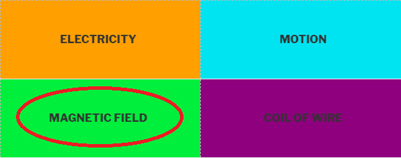
In a car, we use an Ignition Coil to step up the 12V battery voltage to the 5,000-15,000V required. To create this high voltage electricity, we need: Magnetic Field Motion Loops of wire
In order to induce high voltage electricity, we must move a magnetic field past loops of wire. But where do we get this magnetic field from? Well, to create a magnetic field, we need: Electricity Motion Loops of wire
So, inside an ignition coil, we have TWO sets of loops – one to run voltage through to create a magnetic field, and one to induce voltage through, by the moving magnetic field we created. Because one side of the coil uses low voltage to create a magnetic field, it is called the PRIMARY CIRCUIT. Because one side of the coil uses that magnetic field to create high voltage, it is called the SECONDARY CIRCUIT. The secondary circuit always has very large, thick, insulated wiring to keep all the high voltage inside.
|
THE PRIMARY CIRCUIT |
The purpose of the PRIMARY CIRCUIT is to TRIGGER the SECONDARY CIRCUIT (ignition coil) with low (12V) voltage.First, LANGUAGE – you need to know what the heck I’m talking about:
Electricity: the purposeful and directed flow of electrons Circuit: a PATH for electricity to flow through. It must start at the positive side of the battery, include everything including wire and electrical components, and return to the negative side of the battery. Voltage: An Electro-Motive-Force that PUSHES electrons through a circuit. The higher the voltage, the greater the PUSH. Voltage is measured in Volts. Current: The SPEED at which electrons will flow. It is dependent on both the Voltage (PUSH), and the resistance of the Circuit (less resistance = more flow). Current is measured in Amps (or Amperes). Load: Converts electrical energy into other forms of energy (heat, light, sound, motion, etc.). It does this by resisting the flow of electricity through some device (defroster, headlight, horn, fan, etc.). Loads and Resistance is measured in Ohms Source: The BATTERY, the provider of energy Ground: The negative side of the battery. To save weight and wire, all electric devices connect to the metal frame of the car, which connects to the negative side of the battery (houses have a HOT and a NEUTRAL, and both are wired to whatever we need to work, because wood doesn’t conduct electricity well). Magnetic Field: invisible polarized forces that surround an electrically charged wire.
If we hook 12V up constantly to the coil, the magnetic field will just be there. It won’t be growing, shrinking, or changing. This magnetic field is not movement, so it cannot make the secondary side of the coil create high voltage. In order for the primary magnetic field to induce voltage in the secondary windings of the coil, we need to make this magnetic field move. When a magnetic field is being turned on or turned off, it is growing or shrinking (respectively) – this is the movement we are looking for. We need to find a way to open and close the primary circuit. We need a trigger mechanism. Traditionally, this was done with a simple mechanical switch that ran off the engine. This “switch” is called “breaker points” because they “break” their “point” contact to collapse the magnetic field.
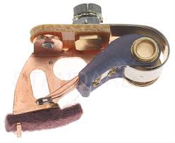
Breaker Points. The felt on the bottom holds oil which lubes a rotating Cam whose lobes make the Breaker Points open and close. These last about 20,000km or less until they lose their effectiveness. Breaker Points SuckFlowing electrons do not want to stop – and while they ARE flowing through the points when closed, when the points open they will try to “jump the gap,” called “arcing.” Arcing will eat away at the contact surface, eroding them and making them less effective, and quickly! How Can We Make Breaker Points Last Longer?ONE WAY:REDUCE THE ELECTRICITY GOING THROUGH THEM – We can add a RESISTOR (called a Ballast Resistor) to absorb some of the voltage, knocking it down from 12V to 9V. This reduces the PUSH, which reduces the chance of electricity “arcing” across the breaker points when they open (the “arcing” kills points). 9V isn’t enough voltage to start the car while it is cranking though, so a ballast resistor is usually bypassed during cranking.  A ballast resistor reduces voltage (less “push”) at the breaker points to reduce arcing ANOTHER WAY:SEND THE “ARC” (A VOLTAGE SPIKE) INTO A CONTAINER TO BE STORED INSTEAD – We can add a CONDENSER (a “capacitor” – a storage container for electricity) to give the electricity somewhere to go instead of arcing. To the electrons, a capacitor “looks” like it has an actual path to the ground, but it doesn’t actually. Since the electrons “think” they have a path to ground, they pack themselves into the condenser trying to get to ground instead of arcing.  A condenser is just two sheets of metal REALLY close together (but not touching) – the electricity “sees” ground, and packs onto the metal trying to get there. By the time the electrons figure out they’ve been fooled, the points are too open for them to go back.
CONSTANT MAINTENANCEPoints also suck because the plastic rubbing block wears out over time, reducing the gap. Therefore, they need frequent adjustment (points open less, reducing spark output, as well as engine power!). Replacing and adjusting breaker points was a key component to the “Engine Tune Up.” They typically lasted a year (20,000km). Back in the bad old days, you’d get your vehicle “tuned” every year, which included (among other things) new points and condenser. If you didn’t change them, your car would eventually run worse and worse and worse until it didn’t run at all TO ADJUST:
LUCKILY, this has evolved into an almost zero-maintenance system (more on that in a bit).
The basic PRIMARY CIRCUIT consists of:Battery – provides the power to run the system. Ignition Switch – allows the driver to turn the system on and off. Ballast Resistor – reduces battery voltage to the points to prevent arcing when they open (help them last longer). NOTE: This is bypassed when starting, to get as much voltage to the coil and as strong a spark as possible. Points – a mechanical switch, driven off the engine, that acts as the triggering mechanism. (Old School technology). Condenser – Stores voltage when the points open to prevent arcing (help them last longer) Primary Coil – loops of wire inside the ignition coil – produces a magnetic field so we can induce high voltage in the secondary coil. Wires – join all the components together.
NOTE: You could make a simple Theft-Deterrent or “Kill Switch” by putting a hidden switch somewhere in the PRIMARY CIRCUIT, and nobody can start the car but YOU.
|
TRIGGERING MECHANISMS |
THESE ARE ALL JUST DIFFERENT “TRIGGERS“:Breaker PointsYou just covered these. Go back and review. All they do is turn the coil on and off.
But breaker points suck because the contacts wear from arcing, and the rubbing block wears making the gap get smaller and smaller, so we need something that does not actually contact at all….
ELECTRONIC IGNITION!1. Trigger Wheel and Pickup Coil (Yay 1970’s)One of the first and most common types of electronic ignitions is the Trigger Wheel and Pickup Coil. This type is also very easy to retrofit into a points-type distributor. The TRIGGER WHEEL is just a spikey, toothy wheel that rotates, usually inside a DISTRIBUTOR. Its purpose is to DIRECT a Magnetic Field. The PICKUP COIL consists of a MAGNET and a LOOP OF WIRE. Its purpose is to send a VOLTAGE SIGNAL to trigger the coil. When two adjacent (means “beside each other”) TEETH of the Trigger Wheel are lined up with the Loop of Wire AND the Magnet, the Loop of Wire sees the magnetic field get STRONGER – in essence, it is “Moving” which sends a freshly created Voltage Signal to a chip that turns off the Magnetic Field in the Ignition Coil. It’s the Square of Electrical Fun again! Iron STRENGTHENS magnetic fields (magnetic fields LIKE to travel through Iron)
This system will give a “square-ish” Sine Wave signal.
2. Hall Effect Pickup (Yay 1980’s)This system switches when the magnetic field at the Hall Effect device is interrupted by a passing metal tab. Interrupting the magnetic field REDUCES the strength of the magnetic field, which makes it COLLAPSE, which sends a (dropping) voltage signal to the Ignition Module, which turns the coil off. the This system will give a Square Wave signal.
3. Optical Pickup (Also 1980’s!)This uses Light Emitting Diodes (LEDs) and photo diodes (receivers). Light signals work quicker than magnetic impulses, so this should be very accurate. A slotted plate passes between the LEDs and photo diodes, switching the system through the Ignition Module. This system will give a very Square Wave signal, but is sensitive to dirt buildup.
|
SECONDARY CIRCUIT |
The purpose of the SECONDARY CIRCUIT is to FIRE the spark plugs with HIGH VOLTAGE.The secondary circuit starts at the high voltage side of the ignition coil, and includes all the components up to and including the spark plug. The ignition Coil has actually TWO coils of wire inside it: Primary Windings which create a magnetic field. This magnetic field collapses (MOVES) when the breaker points open. This half is actually part of the Primary Circuit Secondary Windings Responds to the collapsing (MOVING) magnetic field of the Primary Windings, INDUCING electricity through the secondary windings. This half is actually part of the Secondary Circuit. In a multiple-cylinder engine, we need to be able to distribute this spark to the correct cylinder at the correct time. Traditionally we used a “Distributor” which uses a spinning rotor inside a cap. The cap will have “TOWERS” which connect to spark plugs wires that go to specific cylinders, IN THE CORRECT FIRING ORDER/SEQUENCE. The cap and rotor are usually made out of Bakelite plastic, which is a very good insulator. They may develop cracks (you will see “carbon tracking” through the crack – looks like black soot) and are replaced when they become a problem.
FIRING ORDER In order for an engine to run smooth and last a long time, the cylinders are ignited in a certain sequence. An inline-4 will have the Cylinder Order (starting at the pulley end) of 1 – 2 – 3 – 4, however, to balance the forces on the crankshaft, MOST inline-4’s having a Firing Order of 1 – 3 – 4 – 2, which moves the ignition between outer cylinder – inner cylinder – outer-cylinder – inner cylinder. ALL inline 6’s are numbered 1 – 2 – 3 – 4 – 5 – 6 from the pulleys back, and ALL are fired 1 – 5 – 3 – 6 – 2 – 4.
The basic Secondary Circuit consists of:Secondary Coil – the part of the coil that creates the high voltage electricity. Coil High Tension Wire – a highly insulated wire, that takes the high voltage from the coil, to the distributor cap. Also abbreviated to Coil HT Wire, or just Coil Wire. Distributor Cap – a plastic cap which goes on top of the distributor, to hold the high tension wires in the right order. Rotor – spins around on the top of the distributor shaft, and distributes the spark to the right spark plug. Spark Plug High Tension Wires – another highly insulated wire that takes the high voltage from the cap to the plugs. Also called Spark Plug HT Wires, or just Plug Wires. Spark Plugs – take the electricity from the wires, and give it an air gap in the combustion chamber to jump across, to light the mixture.
DO NOT “disable” the ignition by merely unplugging the spark plug wires!The ignition coil is STILL trying to make spark, and will jump to whatever is near it (including YOU!), or ignite fuel vapour near it. Sometimes an “ungrounded” coil will try to short out internally when you do this!Instead, disable the PRIMARY wires that SOURCE the coil with voltage.If you don’t, this will BITE YOU when you are doing various LABS for me that require the ignition to be disabled!WILL YOU REMEMBER THIS ON THE SHOP FLOOR?Watch Vice Grip Garage “Jeep Wagoneer” episode where he sets his engine on fire because of NOT doing this correctly! |
SPARK ADVANCE |
THE PURPOSE OF SPARK ADVANCE IS TO MAKE SURE WE HAVE MAXIMUM CYLINDER PRESSURE OF COMBUSTION REGARDLESS OF ENGINE SPEED OR ENGINE LOADMR.WELLWOOD’S CLASSROOM LESSON:
This. THIS! THIS IS WHERE THE MAGIC OF A “TUNE” IS!Absolutely guaranteed:
We want to have MAXIMUM CYLINDER PRESSURE from combustion. Whether it’s full throttle acceleration, or cruising on the highway. MAXIMUM CYLINDER PRESSURE means we are getting ALL the power we can from our fuel. Burning fuel takes TIME. And the maximum force of combustion does not happen instantly – it takes TIME to build. Because of this, we actually have to start burning the fuel BEFORE the piston is even finished the compression stroke. YES! – that means we are igniting the air and fuel WHILE THE PISTON IS STILL GOING UP! As the fuel burns, it builds in pressure, and by the time the piston has passed Top Dead Center (TDC), the combustion forces have expanded enough to start acting on the piston. In most engines, we start ignition around 10° Before TDC (BTDC). This is called “Base Timing” or “Static Timing,” and is usually adjustable. Some (not all) engines can gain some power by advancing the timing a couple degrees (“advancing” means having the ignition occur sooner, ie 13° BTDC instead of 10° BTDC). Timing is usually adjusted by turning the distributor – it can rotate when you loosen its hold-down clamp. Making the spark plugs fire sooner is “Advancing the timing.” Making the spark plugs fire later is “Retarding the timing.” Electronic Ignition rarely needs the timing adjusted because there is nothing in the distributor to wear out. hopefully nobody adjusted it wrong in the first place. It’s normally a “set it and forget it” kind of thing. Base Timing is always set at a specified idle speed and it is important to be AT THAT SPEED (more on this later) Most computer-controlled engines constantly ALTER the ignition timing to maximize power and/or economy. Most computer-controlled engines constantly ALTER the ignition timing to get a smooth idle. Most computer-controlled engines will UN-TUNE your engine if you’re running the low-octane gas when you should be running high-octane gas. (Running high-octane gas when you only need low-octane gas does NOT improve power OR economy, despite what the commercials say).
To check or set base timing on computer-controlled engines, you may need to put the computer in an “adjustment mode” or “diagnostic mode” so it will stop self-adjusting on you. Always consult the service manual for the specifics of your vehicle on how to do this.
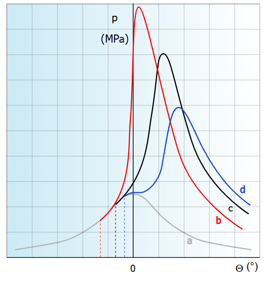
Cylinder Pressure During Combustion:
(image from Wikipedia)
“MPa” (in the image above) is MEGA-Pascals – cylinder pressure that in this case is 1000x more than atmospheric pressure. EXCESSIVELY HIGH cylinder pressure is what destroys pistons, bends rods, and hammers bearings.
|
MECHANICAL ADVANCE |
THE PURPOSE OF MECHANICAL ADVANCE IS TO MAXIMIZE POWER BASED ON ENGINE SPEED
*In MODERN vehicles, this is all controlled by a computer, but the IDEA is the same. Mechanical Advance affects POWER. The faster we run the engine, the LESS time we have for combustion, except burning fuel still takes time. Because of this, we have to start burning the fuel EVEN SOONER. Yes – that means we might even be igniting the air and fuel while the piston is half-way up the cylinder! If we did not advance the timing as engine speed increased, the engine would have very little power because the maximum force of combustion would end up too late – chasing the piston down the cylinder instead of pushing it. As the engine speed increases, we need a relatively linear increase in timing to make decent power. This is called MECHANICAL ADVANCE because it has traditionally been controlled by centrifugal weights. A crappy combustion chamber design will require MORE advance, whereas a good combustion chamber design will require LESS advance.
THERE IS “TOO MUCH OF A GOOD THING”Too much advance is not good – if ignition happens too soon, the force of combustion will try to push the piston back down when it is on the way up. This results in a HUGE cylinder pressure SPIKE that might even cause “knocking” or “pinging” that you can hear inside your engine – this will eventually eat holes through the tops of your pistons!!
SMALL BLOCK CHEVY EXAMPLES: At idle, the spark can occur close to Top Dead Center (TDC). Combustion loses its effectiveness within 23° of crankshaft rotation after TDC At 1200 RPM the spark must fire the mixture at 18° before TDC in order to have the combustion complete by 23° after TDC. At 3600 RPM the spark must fire at 36° BTDC in order to have the combustion complete by 23° after TDC.
WEIGHTS & SPRINGSTo advance the timing (old-school advance), small springs hold back advance weights in the distributor, either above or below the breaker plate. As distributor speed increases, these weights are able to overcome the tension of the springs, the weights fly out, and the distributor cam, or timer core advances in relation to the distributor shaft.
Mechanical advance can be checked very easily, and should always be checked during a tune-up. For this, you are going to need a Timing Light. A Timing Light connects around a spark plug wire, senses the spark happening, and flashes a light at exactly the same time, making Timing Marks on the engine (usually a notch or groove in the crankshaft pulley, and a pointer on the timing cover) appear “motionless” (like a strobe light at a dance party). When you’ve got a timing light on the engine, rev it up a bit, the timing should advance as RPM increases. You’re going to totally miss this sentence. It might be on the quiz, I can’t remember.
Advance Re-Curving
A stock engine should theoretically be happy with the factory’s designed advance curve. The factory will have an advance curve that is generic, safe, and forgiving (too much timing can destroy engines – “Wiki: Engine Knocking”). However, HUGE gains in power can be made if you are willing to live a bit closer to the ragged edge. Pictured above are parts of a “re-curve” kit for my Crusty Chevy truck. The engine is far from stock, had a VERY high compression ratio, and the factory advance curve would destroy the engine real quick. Through different weights and springs, I could tailor the advance curve to suit the engine. To keep track, springs are labeled Heavy, Medium, Light, and “unlabeled” for what came in my aftermarket distributor, and un-clipped for what came in the original distributor. I ended up using one light and one medium spring to get 34° advance all in at 3000rpm. Any more advance, and the engine would KOCK (detonation = engine death).
Adjust Your Ignition Timing to Make the Most Power:
|
VACUUM ADVANCE |
THE PURPOSE OF VACUUM ADVANCE IS TO MAXIMIZE FUEL ECONOMY BASED ON ENGINE LOAD
*In MODERN vehicles, this is all controlled by a computer, but the IDEA is the same. Vacuum advance affects ECONOMY. When you are cruising, and the throttle is mostly closed, there is high vacuum in the intake system. The fuel molecules are really far apart inside the combustion chamber – you need to add some MORE advance so they all have time enough to burn. This extra advance when cruising can really improve our fuel economy. Since cruise usually has high manifold vacuum (very little throttle opening), and since traditionally this type of advance used to run off a source of manifold vacuum during cruise, it is called “Vacuum Advance.”
Vacuum is run through a rubber hose to a Diaphragm (this is a sealed container with a rubber divider down the middle). As vacuum is applied to one side (you can even suck on the hose with your mouth!), the rubber diaphragm moves, and a rod attached to the other side pulls the breaker plate (the plate that the points attach to), making the points open sooner in the rotation of the distributor cam.
Vacuum advance can be checked very easily and should be checked as a part of every tune-up. You don’t need a timing light or anything. With the engine idling, apply a vacuum with a vacuum pump, or by sucking on the vacuum advance line with your mouth. The engine RPM should change. If it doesn’t change, the vacuum advance diaphragm is ruptured and should be replaced. Some vehicles may have Vacuum Advance happening at idle. When setting base timing, it is usually recommended to disconnect and plug the Vacuum Advance line when setting base timing.
Centrifugal and vacuum advance work together to modify the advance curve of the ignition system to maximize fuel economy, maximize power, and minimize emissions.
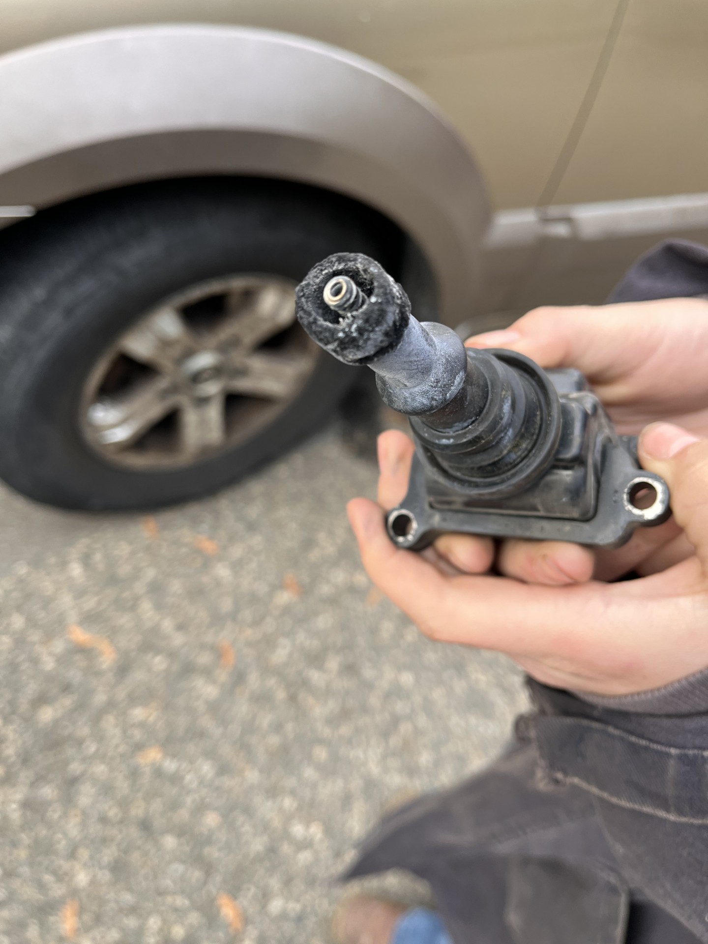
Adjusting Vacuum AdvanceIn the case of most domestic vehicles, there are a large number of Vacuum Canisters that open at different vacuum levels, and/or move the breaker plate different degrees of advance. For normal people, use whatever the engine is supposed to come with. For people like me, I pour through the specs and pick (and test) the ones that will work best for the engine I built. The Vacuum Canister shown below has a HEX on the vacuum end – this means it’s adjustable, and you can change the amount of vacuum (high or low) you need to make it open. The blue piece of metal is a “limiter” I fabricated.
The limiter (blue metal shown above) provides a specific size slot for the arm of the vacuum advance cannister to move, limiting how much vacuum advance I get under cruise. HUGE gains in fuel economy can be gained if you are willing to live closer to the ragged edge of engine knock. In the case of the high-compression engine in my Crusty Chevy, the ragged edge isn’t very far away. This piece of metal limits the vacuum advance to 12°. Not shown is a similar 10° limiter I also made, which is currently on the truck.
Ever Danced with the Devil in the Pale Moon Light?</batman (1989)>A “Factory” tune is SAFE and RELIABLE, but might not be giving you all the power it could.We can change it, and really maximize your engine’s power! Maybe even fuel economy!But if we change the Spark Advance a bit too aggressively and the fuel DETONATES instead of burns, bad (expensive) things happen.Changing Spark Advance aggressively is kinda like Dancing with the Devil; It can be really exciting, but there is always a price. Sometimes the engine itself pays that price.POWER vs. LONGEVITY
|
KNOCK SENSORS |
|
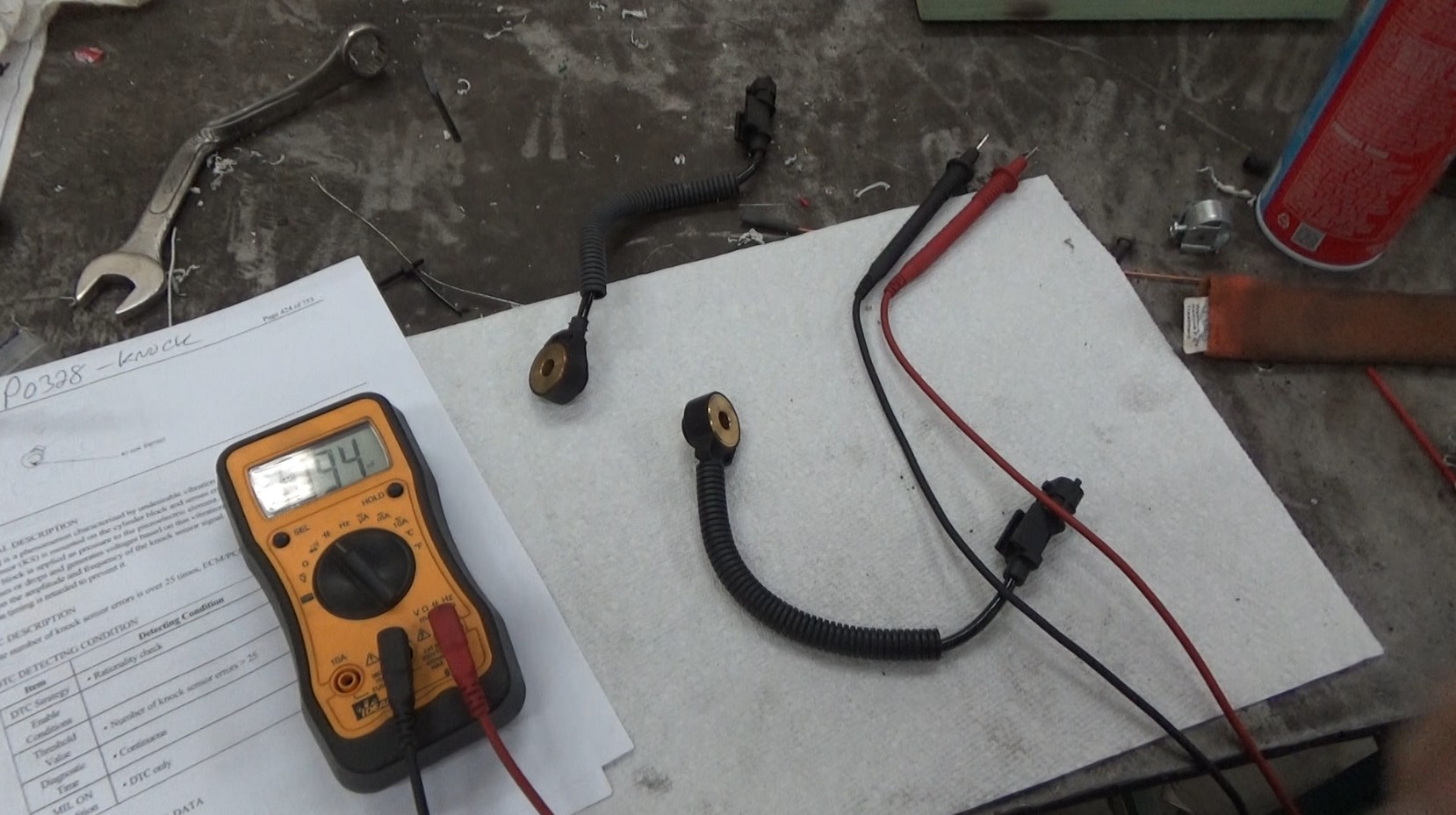
Just like the OXYGEN SENSOR (O2) in Fuel Injection give the ECU (computer) FEEDBACK on whether the fuel mixture is correct or not… The KNOCK SENSOR also gives FEEDBACK to the ECU on whether the spark timing is correct or not. It usually screws right into the side of the engine block near the cylinders. It is VERY FUSSY about being torqued properly (you can break it by over-tightening), and having NOTHING on the threads.
The Knock Sensor is uses piezoelectric crystals that give voltage under pressure. They essentially “hear” the sound of detonation (knock) inside the engine, and a voltage signal is sent to the ECU. When the ECU sees this signal, it starts to pull back timing (you get less “advance”) to save the motor. With the Knock Sensor working, the ECU can maximize your power AND fuel economy, by making sure you are getting all the spark advance your engine can manage. There is a catch…If your engine is designed for Premium Fuel and you put Regular Fuel in, the engine might see Knock, and the computer will pull timing to save the engine and this will cost you both power and fuel economy. The question is – is the cheaper fuel going to offset the increased fuel consumption? If your engine is designed for Regular Fuel and you put Premium Fuel in, the engine MIGHT increase the timing, or it might not. Usually, there is ZERO GAIN in running a higher octane fuel than you need, despite what the commercials tell you. If you have a turbocharged engine, DO NOT run the cheap gas – ALWAYS run Premium. SPECIAL NOTE: ONLY buy OEM Knock Sensors (Original Equipment Manufacturer)
Are you going into the trade? LEARN: Diagnosing a bad Knock Sensor or bad ECU.
|
EVOLUTION OF IGNITION |
WE’VE COME A LONG WAY FROM 1890!(~1975) Breaker Points became ELECTRONIC IGNITIONThe Breaker Points would wear out – so they were replaced with Electronic Ignition which used either a magnetic or optical trigger A Magnetic trigger is shown below – the magnet is the rectangular “sandwich” piece on the left, the black rounded part in the top left is a loop of wire, which senses an increase in the magnetic field strength when the rotating spike is aligned with both it (where the feeler gauge is) and the magnet. Do you know why a Brass feeler gauge is used for this? There is a reason! (*cough*magnet*cough)
(~1985) Mechanical & Vacuum Advance became COMPUTER CONTROLLED IGNITIONThe distributor advance weights would stick, springs would break, vacuum advance canister would leak, hoses would leak – so they were included in the Engine Control Module (ECM), which now controlled both mechanical and vacuum advance, using RPM and Engine Load as references.
(~1995) Distributor Ignition became DISTRIBUTORLESS IGNITIONThe Distributor itself would wear out, along with the cap and rotor – so they were replaced with Distributorless Ignition which usually shared one coil with two cylinders (a V8 would have four coil packs). These coils would fire TWO spark plugs (on TWO DIFFERENT CYLINDERS!) at the same time – but while one plug was used for combustion, the other plug was wasted on a cylinder during the exhaust stroke. This is called a “Waste Spark” system.
I’ve converted engines to Distributorless Ignition. I used a “36-1” Toothed Wheel and a Crankshaft Position Sensor on the crankshaft as a “trigger” for the computer. A “36-1” is a 36-tooth wheel that is missing 1 tooth – the missing tooth indicates Top Dead Center (TDC) to the computer.
(~2005) Spark Plug Wires became COIL ON PLUG IGNITIONThe Spark Plug Wires would wear out (they build up resistance inside) – so they were replaced with each cylinder getting its own coil: Coil On Plug (COP).
(20xx?) Spark Plugs???These have not evolved yet – invent something, and you will be RICH RICH RICH!These are the last consumable item in the ignition system today. You have a choice of basic Copper-Core plugs, Platinum plugs, Iridium plugs, and a whole myriad of electrode shapes and types. Spark plugs are like ice cream flavours – use the one that make you happy. CONTRARY TO THE TV COMMERCIALS, the fancy extra-“whatever” spark plugs that you can buy offer no performance gain; electricity ONLY takes the EASIEST PATH, and that is ONE path only.
TRUE STORY BRO! A student had a car that ran rough. Also had a Trouble Code that said “Misfire Cylinder #4.” I always like to look for the easy/cheap fixes first. Could be a bad spark plug (cheapest), or a bad spark plug wire (still cheap), or a bad ignition coil (not cheap). The engine had Coil-On-Plug, except #4’s coil had exited the chat. $170:
|
TUNE UP |
THE PURPOSE OF A TUNE UP IS TO MAKE SURE EVERYTHING IS OPERATING PROPERLY
“TUNE UPS” DO NOT EXIST IN MODERN CARS!Today, a Tune Up is more a marketing scheme than an actual service. In today’s vehicles, there is nothing to “tune.” You can, however, inspect and ensure everything is working perfectly. Older vehicles still have parts that wear and/or need adjusting. Points & CondenserThe points must be replaced and adjusted at the time of a tune-up. They are set by adjusting their open gap. – a CRITICAL measurement. Dwell is a better way to adjust points. “Dwell” is the number of degrees of distributor cam rotation the points are closed for, can be measured using a Dwell Meter (it measures the “closed time” and gives you what that angle is). Dwell, coil saturation time, and cam angle are all the same thing. Simply hook up a dwell meter to the coil. ( red lead to negative, black to engine ground) Crank the engine with the distributor cap and rotor off, and adjust the fixed contact of the points until the correct dwell reading is obtained.
If there is a range in the dwell specification, adjust the points to the low end of the range because dwell will always increase as the rubbing block wears down.
RotorThe ROTOR directs the Coil Output to the correct TOWER on the Distributor Cap. It snaps onto, or is held by screws, to the top of the distributor shaft and only goes on one way. The rotor is made of “Bakelite”, a type of plastic that insulates well and resists heat. It is, however, quite brittle. They sometimes “burn” because of the high voltage electricity, and the brass edges wear away from sparking inside the cap. When there is evidence of burning (carbon pathways burned into the plastic), or significant wear on the brass, they are junk.
Distributor CapThe Distributor Cap connects wires from each TOWER to the CORRECT spark plug. The wiring of this is 100% CRITICAL. The distributor cap is also made of Bakelite. It has brass, copper, or aluminum inserts in it to conduct the electricity to and from the rotor and the high tension wires. The cap usually has ribs on the inside to prevent arc-flashover between the terminals. There is one insert in the center for the coil HT wire, and inserts around the outside for the spark plug HT wires. The plug wires are pushed into these terminals in the firing order. Good quality caps have copper or brass inserts and not aluminum. There is arcing between the cap and rotor and that arcing causes oxidation and erosion of the inserts. Aluminum oxide (created as the arcing occurs inside the cap) is a very effective abrasive and causes wear on the distributor shaft bearings. DURING A TUNE-UP, the rotor should be checked for worn electrodes, cracks, and punctures (these are places where the electricity has burned through the rotor to the distributor shaft). DURING A TUNE-UP, the cap should be checked for any wear on the inserts, and evidence of “carbon tracking” (these are places where the electricity has made another way to ground, or one of the other terminals in the cap). Both cap and rotor should be checked during a tune-up for carbon tracks and erosion and cracks, but they don’t necessarily have to be replaced unless they show wear.
The secondary side of the ignition is sensitive to water. Four-Wheelers often seal their ignition system with silicone to help keep moisture out of the distributor cap. Any water in there will short out the electricity instead of firing the plugs. It’s an easy fix though – remove the cap, dry it out (you can even spray it with WD40 – “WD” stands for Water Displacement!)
High Tension (HT) WiresThe HT leads are highly insulated to prevent the electricity taking a short circuit to ground. There are usually one plug wire going to each spark plug, and one coil wire going from the coil to the center of the cap, although some ignition systems place the coil directly inside the distributor cap.
HT leads are usually carbon core; very much like a little piece of string impregnated with graphite. Only some race cars (with no electronics) use an actual conductor made of copper – their intense magnetic fields when sparking fry circuits! The insulation makes up a large percentage of the diameter of the wire, and is usually made of silicon in modern wire sets.
DURING A TUNE-UP the wires should be checked for evidence of burn through, deterioration of the wire, or boots, or any abnormality.
The plug wires should be separated from each other, and never bundled together. Bundling the wires causes the moving spark from one wire INDUCING a spark in an adjacent wire (there is electricity moving through them, so a magnetic field is moving too, and now you have a Magnetic Field Moving past Wires!). The plug wires can be checked on an engine analyzer, or oscilloscope for how much voltage is going through them. High firing lines (high voltage) indicate open circuits caused by a broken wire or spark plug, or a wide spark plug gap. Low firing lines indicate a short, caused by leakage to ground. This could be a wire laying across an exhaust manifold or the cylinder head and the insulation worn away. If you don’t have an oscilloscope, HT leads can be checked with an ohm-meter. There should be about a thousand ohms of resistance per foot of wire. When pulling plug wires off the spark plugs, twist and pull the BOOT, DO NOT YANK ON THE WIRE ITSELF!This will cause the wire to break inside and although it may still work right then, it will give problems down the road as the wire burns back in both directions from the break.
Wire sets don’t necessarily have to be replaced during a tune-up, but they should always be checked. When they fail, they usually stop the spark from getting to the plug.
|
SPARK PLUGS |
THE PURPOSE OF THE SPARK PLUG IS TO PROVIDE A POINT WHERE A HIGH VOLTAGE SPARK CAN IGNITE COMPRESSED AIR AND FUELThe spark plugs are the last remaining part of a modern ignition system that need servicing on a regular basis. While spark plug manufacturers have tried to market many different spark plug designs in an effort to make more power or last longer, there are some nice improvements: Standard Plug: Lasts about a year, costs about $2.50 each Platinum (also Iridium): Lasts about 5 years, costs about $11 each There is no magic in spark plugs. They either spark, wear, or foul. Multi-tipped spark plugs, split-tipped plugs, and other mystery concoctions only make the plug last longer (foul slower) – the spark will only jump the best gap, not multiple gaps. They will not give you more power.
SPARK PLUG SIZE AND SHAPEThe plugs must have the correct “reach”, or length of the threads, diameter, sealing method, and heat range. The two plugs on the right require the use of a seal ring, or gasket to prevent compression leakage past the threads. The plugs on the left do not require a gasket. One design isn’t any better than another, it’s just what the manufacturer chose.
SPARK PLUG HEAT RANGEThe spark plug must run at the correct temperature. If the plug runs too HOT (above 900°C) it will glow red hot, and the fuel mixture will start on fire all by itself, not when it is supposed to. This is called pre-ignition, and will destroy an engine. If the plug runs too COOL (below 450°C) it will quickly foul up with crud because it never cleans itself. Note the short heat path in the plug on the right. Remember, the hottest part of the plug is the center electrode. The shorter the distance the heat has to travel to the coolant, the cooler the plug runs. A hot spark plug has a longer insulator nose.
High performance and high compression engines have a great deal of heat in the combustion chamber (remember, it’s the HEAT that pushes the pistons down) and they don’t require any “artificial” or “extra” heat at the spark plug to keep things hot. High Performance engines use cold plugs. The high-compression engine in my ’77 Silverado ran spark plugs that were two steps colder than stock to help reduce detonation The turbocharged engine in my ’61 Apache ran spark plugs that were two steps colder than stock to help reduce detonation …and I also run WAY less spark plug gap so the boost doesn’t “blow the spark out” (0.025″ instead of 0.040″) …and I run WAY more fuel under boost …and I spray methanol into the airstream under boost to cool it down even more Low performance, low compression engines don’t have a great deal of heat in their combustion chambers and therefore need to keep the plugs hot in another way; they use hot spark plugs. LIFE HACK: Sometimes a really tired, oil-burning engine will quickly foul the spark plugs with burnt oil. Running a HOTTER plug can help those deposits BURN OFF and make the plugs last longer (but does NOT fix the problem…). . SPARK PLUG NOSE/TIPProjected nose or extended tip plugs take the whole insulator and move it further out into the combustion chamber. This moves the tip into the swirling gasses in the combustion chamber and the tip keeps cleaner than a normal plug and prevents fouling. Some high-performance engine builders switch from a “projected tip” to a “recessed tip” to get the spark plugs to run cooler (I did so on my turbo ’61 Apache).
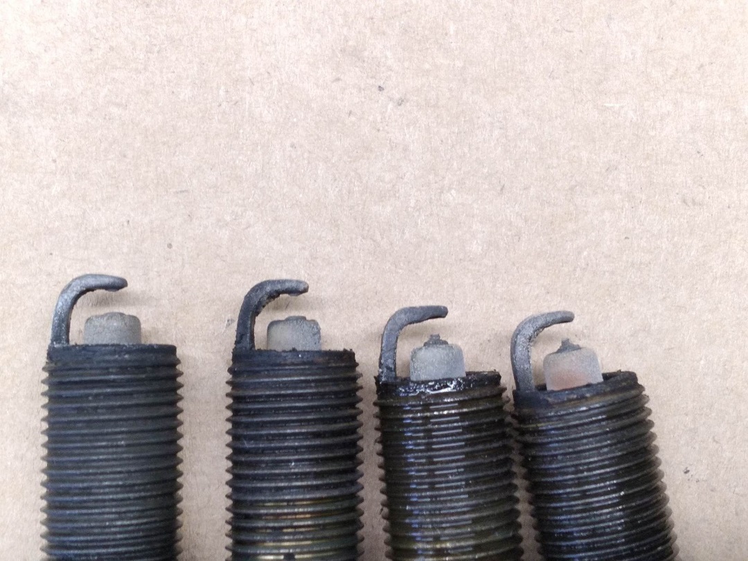
These plugs (below) came out of my son’s PT Cruiser. I suspect they have NEVER been changed since new (310,000km). I’m surprised it ran as well as it did. I’m honestly surprised it ran AT ALL:
READING SPARK PLUGSA technician can tell a great deal about the engine he is working on simply by “reading” the spark plugs. Normal: Brown to grayish-tan colour, slight electrode wear Worn: Rounded electrode Carbon Fouled: Dry, sooty, black deposits – rich mixture Ash Deposits: Light brown crusty – oil & fuel additives Oil Fouled: Oily, wet, black coating – worn rings and/or valves Overheating: very white and little deposits – wrong plug or engine overheating Preignition: Melted electrode – wrong plug, wrong timing, or engine mechanical problem Detonation: Fractured insulator – wrong fuel octane
If you are super hard-core, you can get a Doctor’s “Otoscope” and look WAY DOWN inside the spark plug to get a good read on your engine’s fuel mixture, heat range, spark timing, AND evidence of detonation. That’s a whole ‘nuther science…
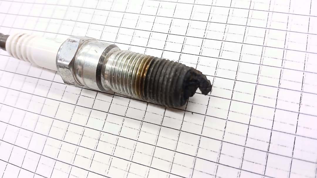
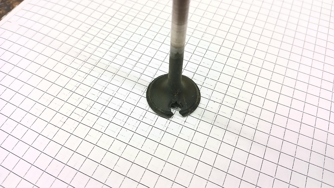
======= TRUE STORY BRO: ====== HOLY CARP!! A student has a 2.3L Mazda 3 that was running bad and had no power. We pulled a spark plug to do a compression test and saw:
Clearly, this cylinder has an issue! Compression test revealed: 175 – 0 – 180 – 175, and a Leak Down test revealed 100% loss in #2. Turned out the exhaust valve was burnt! The student replaced the exhaust valve and the car had so much more power!
======================== SPARK PLUG GAP!The spark plug air gap must be set when the plugs are installed. The gap is determined by the manufacturer. The wider the gap is, the more voltage is needed to jump that gap, the hotter that spark is, the better combustion happens. TOO WIDE a gap, and the Ignition system might not produce enough voltage to jump the gap! (MISFIRE!!) I always use a touch of Never-Seize on the threads so they come out again easily. Some say never to do this, but I’m guessing they’ve never had to remove a cylinder head to remove the broken half of a spark plug. While we have the ability in the shop to clean your spark plugs, spark plugs are not normally serviced at all anymore. Sand blasting the insulator gives it a rough finish and it fouls up easier than when new.
|