[Engine Performance] [Balancing & Blueprinting] [Boost & Nitrous] [Automatics] [Differentials] [Lifting & Lowering]
QUESTIONS – Automatics |
||||||||||||||||||||||||||||||||||||||
|
Mr. Wellwood’s Classroom Lesson: |
||||||||||||||||||||||||||||||||||||||
History |
||||||||||||||||||||||||||||||||||||||
|
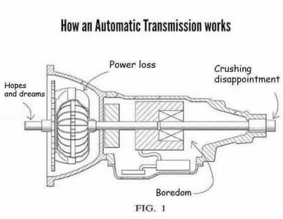
An automatic transmission is merely a transmission where the clutch is applied and released automatically, and the gears are shifted automatically. All this is done through a “fluid coupler” of sorts, and hydraulic pressure applying clutches and bands to drive the appropriate gears. Gear selection is usually chosen by both engine load (vacuum) and vehicle speed (centrifugal governor). The earliest successful automatic was the Hydra-Matic Drive by Oldsmobile in 1940, and the design was sold to many manufacturers including Lincoln (gasp!) and Rolls-Royce. Buick improved the sluggish acceleration of Olds’ fluid coupling by adding a Torque Converter to their Dynaflow transmission in 1948. By the 1960’s, the standard layout was a torque converter and three-speed automatic. It wasn’t until the late 1980’s that we began to see four speed overdrive automatics, with more and more of the transmission being electronically controlled. Today, a manual transmission is indeed a rare thing. Automatics are becoming very efficient, very well controlled, and some can actually provide better fuel economy than a standard transmission because it performs with far greater accuracy than the human driver. One of the coolest new features is providing F1 style “paddle-shifters” at the steering wheel! |
||||||||||||||||||||||||||||||||||||||
Construction |
||||||||||||||||||||||||||||||||||||||
|
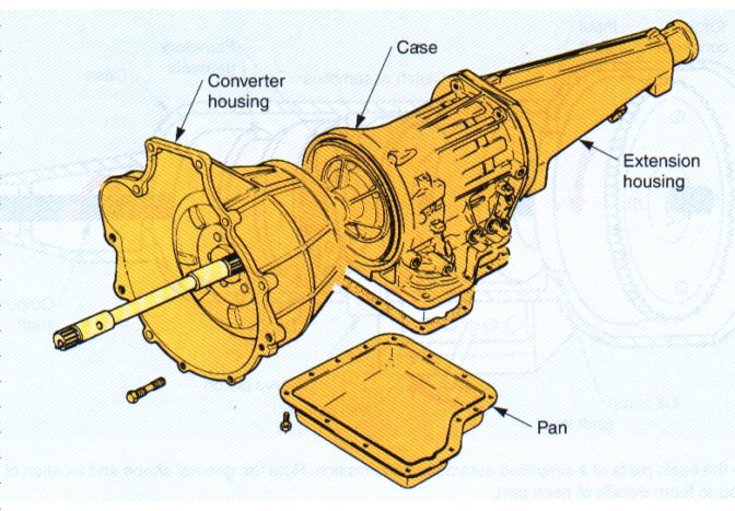
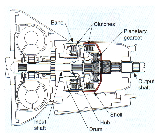
Most automatic transmissions are constructed with a front bell housing, central case, rear extension housing, and lower pan. The majority of the parts are located inside the case itself, installed behind the front pump inside the bellhousing. Servicing of the valvebody is done through the pan. |
||||||||||||||||||||||||||||||||||||||
Components |
||||||||||||||||||||||||||||||||||||||
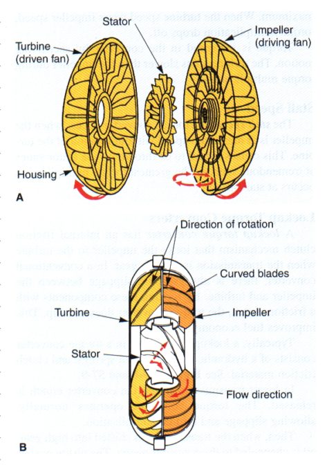
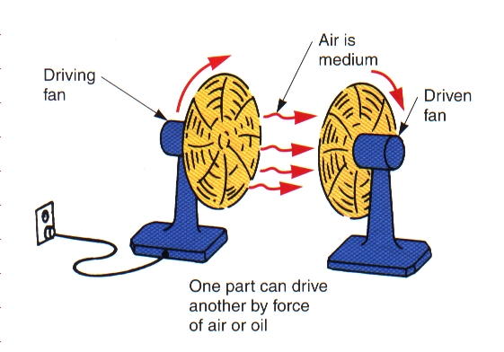
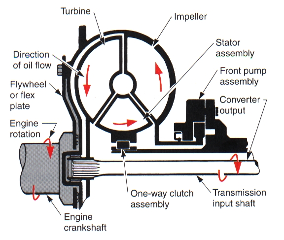
Torque ConverterThis is a Fluid Clutch that connects and disconnects engine and transmission. It uses three components immersed in transmission fluid to distribute power. Impeller: Attached to the flex plate (a very thin flywheel) of the engine, and spins as the engine spins. As it spins, oil is thrown towards the outside of the torque converter housing and onto the vanes of the Turbine. Turbine: Attached to the input shaft of the transmission, it begins to spin when enough oil is thrown onto the vanes from the Impeller. If the Impeller is moving too slowly (engine is at idle), there is not enough force to cause the Turbine to turn. Stator: Attached to the transmission case and locks when there is a difference in speeds between the Impeller and the Turbine. Its vanes re-direct the moving oil inside the converter to improve efficiency and increase torque to the transmission. It is often easier to imagine how a torque converter works by imagining two house fans facing each other. When one is plugged in and running, the other will move because of the air being forced upon it. The fluid circulating in the torque converter can only handle a so much difference of speed between the Impeller and Turbine. At some point, the torque converter starts holding the engine back, limiting its speed. You notice this when you have the transmission in gear, your foot on the brake, and the gas to the floor – it will rev to around 1800rpm and just stay there (or blaze the tires if the brakes can’t hold it back). The maximum speed the engine can attain is called the “Stall Speed” of the torque converter. Stall speed is important to be matched to your engine. The torque converter also “slips” – some of the engine power is lost moving fluid. This has traditionally been the cause of lower fuel economy with automatic transmissions. Today, almost all torque converters “lock up” with an internal electrically-controlled clutch to lock the Impeller to the Turbine for zero power loss.
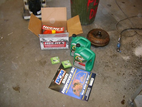
HIGH STALL CONVERTERS A torque converter is specifically-sized to your engine’s power and torque curve, as well as your vehicle’s weight, gearing, tire size, and intended purpose. If you make radical changes to something, it may affect your torque converter in a bad way. When I modify an engine for more high-rpm horsepower, it usually costs me low-rpm torque (I love a choppy idle sound). Now the engine does not make enough power to overcome the fluid friction inside the converter, and the engine wants to stall in gear. If I raise the idle speed so that it doesn’t stall, it just wants to drive. The solution is a converter that has been built with a higher “stall speed.” The stall speed of a torque converter is the speed at which the converter has pretty much stopped slipping. A higher stall speed is kind of a “looser” converter, and can allow a lumpy idle engine to drive like a normal car with an automatic. The cool thing is when you romp on the gas, the torque converter will let the engine flare up to where the engine is actually making power (and thus, the converter’s “stall speed”), and the acceleration is much better! CAUTION: a high stall converter creates a LOT of heat when you’re working it, and heat KILLS transmissions. You want to run the BIGGEST gosh darn transmission cooler you can, and NEVER do any towing. You may want to change the fluid out a whole lot more frequently too.
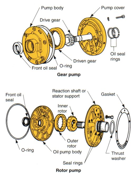
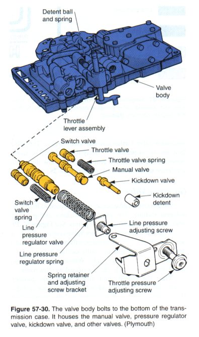
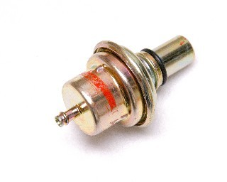
Input ShaftThe input shaft splines into the Turbine inside torque converter. It is only turned when the torque converter turbine is “moving.” Surrounding the input shaft is the Stator Support which splines into the Stator. Oil PumpThe oil pump is mounted right at the front of the transmission case, and is driven by the torque converter housing so that the transmission will receive oil as long as the engine is running. The converter housing splines into the oil pump (do you notice that THREE things spline together with the torque converter? When you place the converter on the transmission input shaft, you need to rotate it a bit side to side so that you hear all three spline together: thunk-thunk-thunk. Input shaft, stator support, oil pump. Valve BodyThe hydraulic brains of the transmission. It will usually consist of the following components: Pressure Regulator: Limits the maxiumum oil pressure developed by the oil pump. Manual Valve: Operated by the shift mechanism and the vehicle operator. Vacuum Modulator Valve: Senses engine load (vacuum) and determines when the transmission should shift into a higher gear. Governor Valve: Senses vehicle speed to help control shifting. Higher speeds cause the governor to move the shift valve and cause the transmission to shift into a higher gear. Shift valves: Uses control pressure to operate bands, servos and gearsets. Kickdown Valve: Causes the tranmission to shift down during acceleration. Usually mechanically operated off the throttle, and often adjustable.
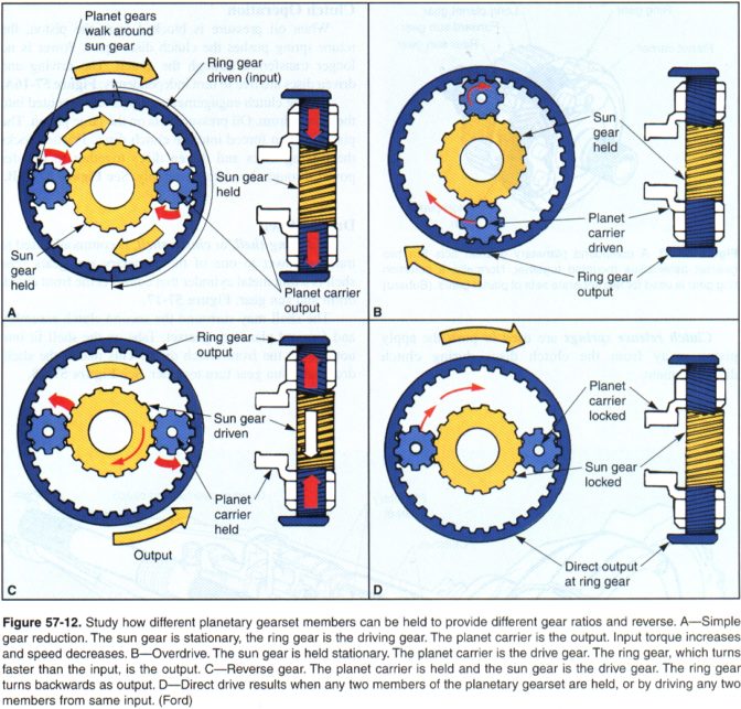
Pistons and ServosActuates the bands and the clutches through hydraulic pressure as determined by the valve body. Simple hydraulics, just like brakes. A small apply piston working a large servo INCREASES force. Planetary GearsetsConsists of a SUN gear, several PLANET gears, and a RING gear.
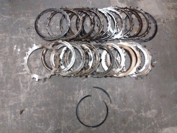
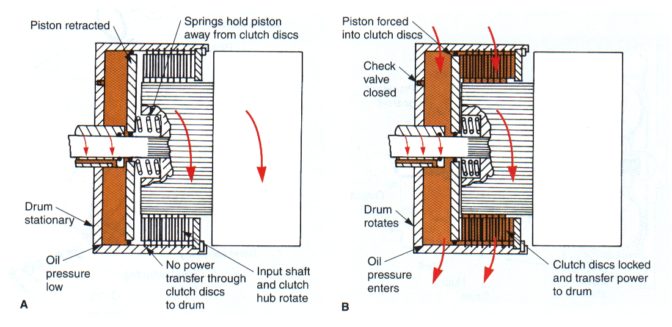
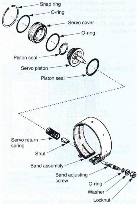
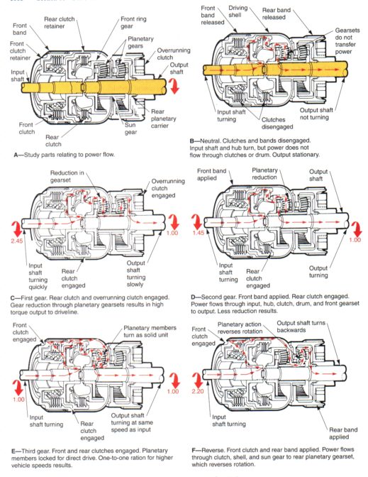
By its name, the planets revolve around the sun. By holding different parts of the planetary gearset, you can get underdrive, direct drive, overdrive, and reverse. Most transmissions use at least two planetary gearsets. Click the picture, and really study at what’s being HELD, what’s being DRIVEN, and what the OUTPUT is doing. The different parts of the planetary gearset are usually held by clutches or bands applied hydraulically. ||||||||||||||||||||||||||||||||||| Video: Simple Gear Sets Clutches and BandsThese are friction devices that drive or lock planetary gearset members. Multiple disc clutches are applied by a hydraulic piston that slides within the clutch assembly. The more clutch plates there are and the larger they are, the stronger the clutch will be. Bands wrap around a drum, and while one end is locked, the other is actuated by a servo piston, tightening the band around the drum. Bands are usually adjustable, and often from outside the transmission case.
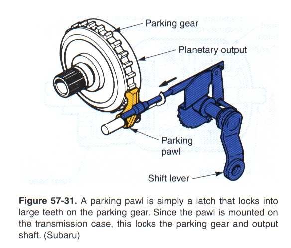
Output ShaftConnects the driving components in the transmission with the driveshaft. Due to the way the transmission is constructed, the input and output shafts are almost touching. “Park” is usually found on the output shaft – a mechanical locking device to keep the vehicle from rolling away, since when the engine is off, there is no hydraulic pressure to keep the transmission in gear. CURIOUS PROBLEM Vehicle would exhibit a loud, nasty, sheet-metal-into-a-fan-blade sound, but only while turning left. Everything was inspected, starting from the easiest (tire rub) and progressing to the most difficult: driveshaft rub, brake issue, wheel bearings, chassis flex, gas tank mounts, frame cracks, worn differential, broken flex plate, etc. 3 years of searching – nothing CAUSE: Missing park pawl return spring. Transmission would try to shift into park by itself when turning left. $1 spring and it was fixed. |
||||||||||||||||||||||||||||||||||||||
Operation |
||||||||||||||||||||||||||||||||||||||
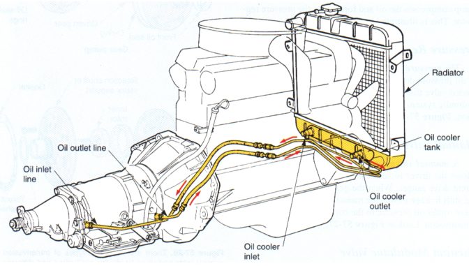
Automatic Transmission Oil“ATF” is a hydraulic oil that has several additives to make it work with the friction of clutches and bands in the transmission. Different transmissions require different oils. Traditionally, Ford transmissions used “Type F” oil which was specially formulated to work in a transmission where friction was a key player in the application of clutches and bands. GM (and virtually everyone else) used “Dexron” which worked best when pressure was the key player. Some drag racers would use Type F in their GM transmissions to make it shift harder. It worked, but not always for long. All hydraulic oils will build up a lot of heat as it is being used. Transmissions will build up a lot of heat when the transmission is working hard: pulling a trailer, four-wheeling, drag racing, and other applications where the torque converter might be at its Stall Speed a lot (huge heat generator). In order for the transmission to last, you need to keep the oil cool. Almost every automatic transmission has a cooler built into the cold tank of the radiator. You will see two high pressure lines leading to the rad from the tranny. If you plan of working your vehicle hard, an “auxiliary transmission cooler” should be installed (looks like a mini radiator which you attach to your radiator, dawg). A cooler can be used instead of the one in the rad, or in-line with the one in the rad. A tranny cooler should be placed in front of the engine radiator to get the coolest air. In my opinion, ALL trucks should have an auxiliary cooler.
And because life is all about balance….
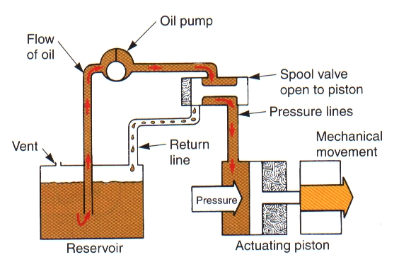
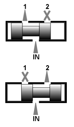
Spool ValvesThe operation of an automatic transmission can be mind-boggling at best, and this topic is often left until your fourth year as an apprentice. If you can break the operation down into the basics, and work through their understanding individually, the automatic transmission is pretty simple. Basically all the gears are selected manually or automatically by spool valves. A Spool Valve gets its name because it kind of looks like a spool of thread. It is placed in a hydraulic cylinder, and can be controlled entirely manually (such as the PRND2L shift control), hydraulically (such as shift control valves) or a combination usually using springs. The spool valve can be situated so that NOTHING flows, or if it moves to one side or the other, can activate one (or more) other systems. Look at a simple two-way spool valve. We have:
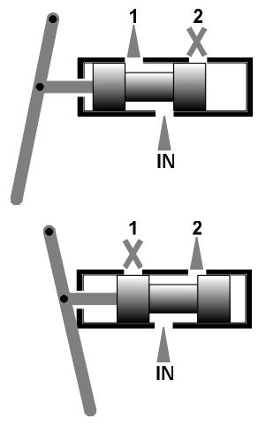
Manual ControlIf we add a control lever to physically move the spool valve for us, WE can control which gear we are in. This is how the Manual Valve connected to our shifter works. We can select Park, Reverse, Neutral, Drive, Second and Low gear. If our transmission were controlled solely by this valve, it wouldn’t be much of an automatic transmission, would it?
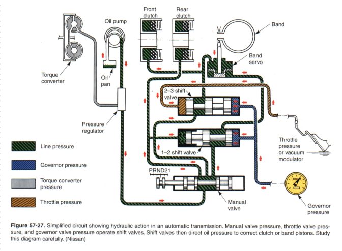
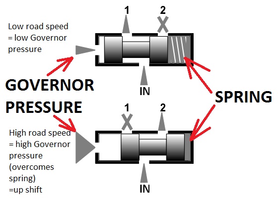
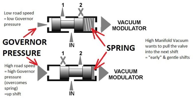
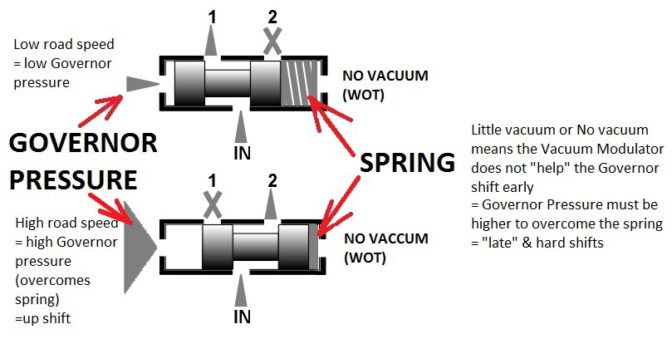
Governor ControlLet’s put in a device that will GOVERN when it shifts. Let’s call it the Governor. Let’s say it increases a hydraulic governor pressure to the spool valve the faster the output shaft of the transmission spins (higher vehicle speed = higher hydraulic pressure). Let’s plumb that governor pressure to one side of the spool valve, and let’s give it a spring to push against on the other side (otherwise even slight pressure would slam the valve all the way over, and it would never downshift). Now, once pressure is high enough to overcome the spring pressure, the valve will move, redirecting the hydraulic fluid to activate second gear. In this case the transmission will ALWAYS shift at a certain speed, whether we want it to or not. This would certainly work, and it certainly would be automatic, though not a very good one. If you are driving your grandma to church on Sunday, you would prefer a low, gentle shift that doesn’t spill Granny’s Gin and Tonic. If, on the other hand, you are pulling a hill at full throttle, you need the transmission to shift at a higher speed so the engine can be well into its power curve to pull that hill. If it always shifted at the same speed, you would never get the engine at maximum power because the transmission would have shifted into a higher gear long ago.
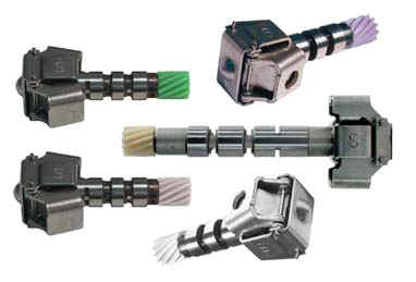
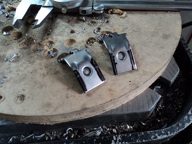
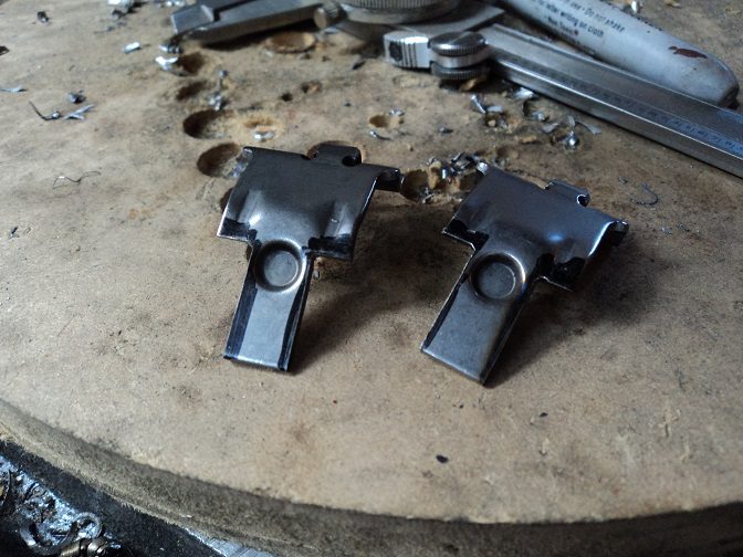
CHANGING SHIFT POINTS I modified these governor weights to raise the full-throttle shift point of the transmission after modifying the engine to make much more high-rpm power.
I did the same thing to another vehicle with a completely stock engine, but I removed too much – the engine over-revved and I blew the motor. Sadness. But then I built another motor with twice the horsepower, and I was happy again. If we want to change shift points based on LOAD not just RPM, we are going to have to modulate the shift. Vacuum ModulatorThis device allows us to shift at a higher speed when we are pulling a hill, and shift at a lower speed when we are not. It adjusts hydraulic pressure by referencing engine vacuum Let’s add to the spring in the previous example a hydraulic pressure that varies with engine load. Maybe modulate the governor pressure with vacuum. Let’s call it a Vacuum Modulator. The spring makes sure it downshifts as you slow down.
If we are at full throttle, we would like later shifts to make the most of the engine’s power. An engine at wide open throttle (WOT) has zero vacuum (throttle is wide open – nothing to pull against). Without vacuum, the spool valve doesn’t get any extra help to move, so it’s all up to the governor working against the spring. This means the road speed will have to be higher before the governor has enough pressure to overcome the spring. This results in later shifts.
If Grandma is just tooling along gently with fairly low throttle (high engine vacuum), the Vacuum Modulator helps the governor move the spool valve easier, and it shifts early. There you have it!
Oh, and today, the shifts are are controlled electronically through programming in the ECU. But they basically do the same thing – early gentle shifts under light throttle; higher and harder shifts under full throttle. ApplicationIn a common three-speed automatic transmission, there are the following parts: Forward Clutch: Applied in any forward gear Low-Roller Clutch: (also called an Over-Running clutch) Used in “Drive” first gear only. It is not very strong, but “automatically” releases (over-runs) when the transmission shifts into second. High-Reverse Clutch: Applied in both High gear as well as Reverse. Low-Reverse Band: Applied in Reverse and Manual Low. Much stronger in Low than the Low-Roller Clutch is. Also provides engine braking when decelerating. Intermediate Band: Applied in second gear only. Easy and quick to apply for second, but takes some time to release shifting into High. Here’s how they work together:
You may need to spend some time studying this power flow through the transmission in this picture: AccumulatorsAccumulators absorb some of the ferocity of the shift – they “cushion” the shift. They are usually a piston and a spring in the hydraulics circuit that applies a clutch or band. When hydraulic fluid goes to apply the clutch, it also fills a cavity that is “cushioned” by a spring (kind of like inflating a balloon and letting the air out slowly, in a twisted, weird way – it takes time to fill, it takes time to empty). Some transmissions are notorious for breaking the accumulator springs, which makes the transmission shift HARD into that gear (I’m looking at you, GM!). Many “Shift Kits” delete accumulators to MAKE the transmission shift harder. The downside of deleting accumulators, it it can be pretty hard on parts, as there is nothing to absorb the “shock” of the shift.” I often delete 3rd and 4th gear accumulators to speed up their shifts. |
||||||||||||||||||||||||||||||||||||||
Modification |
||||||||||||||||||||||||||||||||||||||
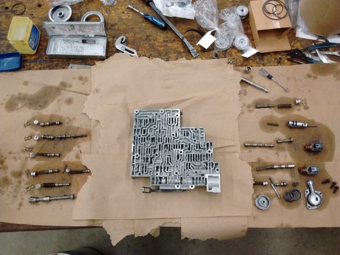
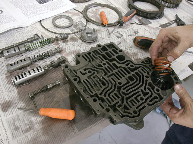
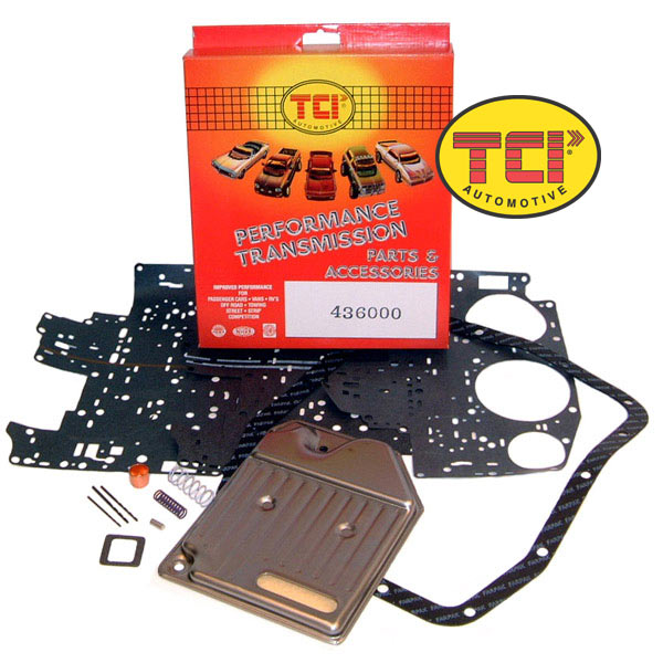
Shift KitsMost performance shift kits for automatic transmissions will usually do three things: Raise shift points Speed up shifts Apply clutches and bands with more force Many kits come with choices on how it will shift. Stage 1: Firm shifts without affecting comfort Stage 2: Very firm, very hard shifts for maximum performance Stage 3: Insanity – sometimes completely manual valve body, no “automatic” operation Installing a shift kit is relatively straight forward. Once you have drained the fluid from the transmission, the valve body must be removed. It is a good idea to have a service manual to do this, as these are not very forgiving if you make a mistake. The kit will come with instructions on what modifications are required. YOU MUST FOLLOW THEM EXACTLY. Usually the metered holes that apply clutches and bands is drilled larger to make it apply faster. Some springs are upgrades, some springs are removed, some valves and springs are disassembled and reassembled backwards. Some valves have ball bearings thrown in to stop them from moving. It really sounds kind of hokey, but it works. Follow the instructions! SHIFT KIT 1 My “University Stress-Reduction Plan” was putting a rowdy V8 into a little Ford Pinto. I built a Frankenstein automatic using the stronger truck case and guts, but the car tailshaft and housing so I could use it in a car. I put in a Trans Scat “Stage II” shift kit, and it was brutal. Even at light throttle it would bark the tires as it shifted. It did not shift smooth ever again. Full throttle shifts were downright scary. And I loved it. SHIFT KIT 2 My ’77 Chevy (mentioned at the beginning) got a B&M “Shift Improver” kit, which had options of “Towing/RV” or “Street/Strip.” Most transmission specialists suggest “for the love of mercy, do NOT follow the directions on that kit, you will grenade your transmission.” So I installed it as the transmission guys recommended. It is nowhere near as brutal as the Pinto was, but it will still chirp second at full throttle. Theoretically the transmission will last a little longer. (Note: this transmission blew up two years later (it was 40 years old), and on rebuild I added another friction and steel to the high/reverse clutch, and used a TransGo shift kit). (Note: I took this transmission apart again three years later chasing a vibration issue. On rebuild removed the TransGo shift kit and did the No Shift Kit Shift Kit mentioned below – it shifted much better into 3rd). NO SHIFT KIT SHIFT KIT The transmission in my V8 Pontiac Firefly got a shift kit using no shift kit. I internally modified the hydraulics to more than double the hydraulic pressure to the high/reverse clutch, and drilled bigger holes in the stock separator plate. I also machined the high/reverse piston thinner to fit another steel and friction for 25% more strength. HALF & HALF The transmission in my ’61 Chevy Apache got part of a shift kit, plus internal modifications. I internally modified the hydraulics to more than double the hydraulic pressure to the high/reverse clutch, and drilled bigger holes in the stock separator plate. I also used thinner high/reverse steels to fit another steel and friction for 20% more strength. I took some reinforced parts from the shift kit, plus fully machine the insides to get rid of bronze thrust bearings and replace them with torrington needle bearings, and re-directed half the forces into the case and away from the rear (now torrington) thrust bearing. I also installed some improved valves in the valvebody, and re-worked the valve body to apply an over-running clutch in regular drive mode. MASSIVE modifications!
|
||||||||||||||||||||||||||||||||||||||
The Future |
||||||||||||||||||||||||||||||||||||||
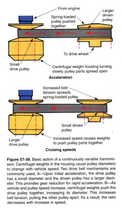
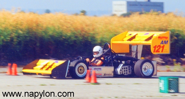
Continuously Variable Transmission (CVT)Slowly becoming more popular is the Continuously Variable Transmission. This type of transmission does not use a set number of forward gears like an ordinary transmission, but rather, the gear ratios are Continuously variable. If you have ever ridden a snowmobile, you have experienced a CVT Transmission: You peg the throttle and the engine revs up to a set speed, and the transmission adjusts itself to bring the sled up to the engine speed. Advantage: Engines are much more powerful and much more fuel efficient if they are designed to operate at ONE speed. Instead of trying to make the engine run as wide a range as possible, we can make the transmission deal with speed and let the engine just makes power. Also tends to be smaller and lighter. Also can increase fuel economy by about 25%. Disadvantage: Currently fairly expensive as the technology is somewhat new. May require a different driving style as you will need to keep the engine speed constant. Joe Cheng’s “Phantom,” pictured here, is the fastest autocross car in North America (a faster car, the “Vancouver Special” is in development). It uses a 3-cylinder snowmobile engine and a CVT. It produces in the neighbourhood of 240hp and weighs 900lbs. If the CVT didn’t work, it wouldn’t be in a no-holes-barred race car.
|

