PART 1 of your Drafting Course.
This in an introductory course in Drafting, establishing basic sketching, designing and CAD skills and techniques in the design and modeling of a variety of projects.
This course is paced fairly quickly with a lot of assignments – try to stay up to date! There is ample time to complete all assignments IF you use your time wisely! Complete each assignment IN ORDER (ask for help if need be). Demos are usually done to keep up with the fastest students.
ALL assignments are a required part of the course.
HAND DRAWING |
|||||||||||||||||
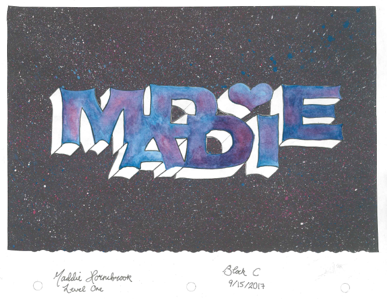
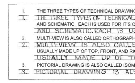
Lettering |
|||||||||||||||||
| Drafting is all about information.
While we need to DRAW clearly and accurately to convey information, when Hand drawings are hand-labeled. Good pencil-control skills in lettering (we know letters) help us sketch our drawings much better (we are learning drawings). ASSIGNMENT:
|
 |
||||||||||||||||
Hand Sketching |
|||||||||||||||||
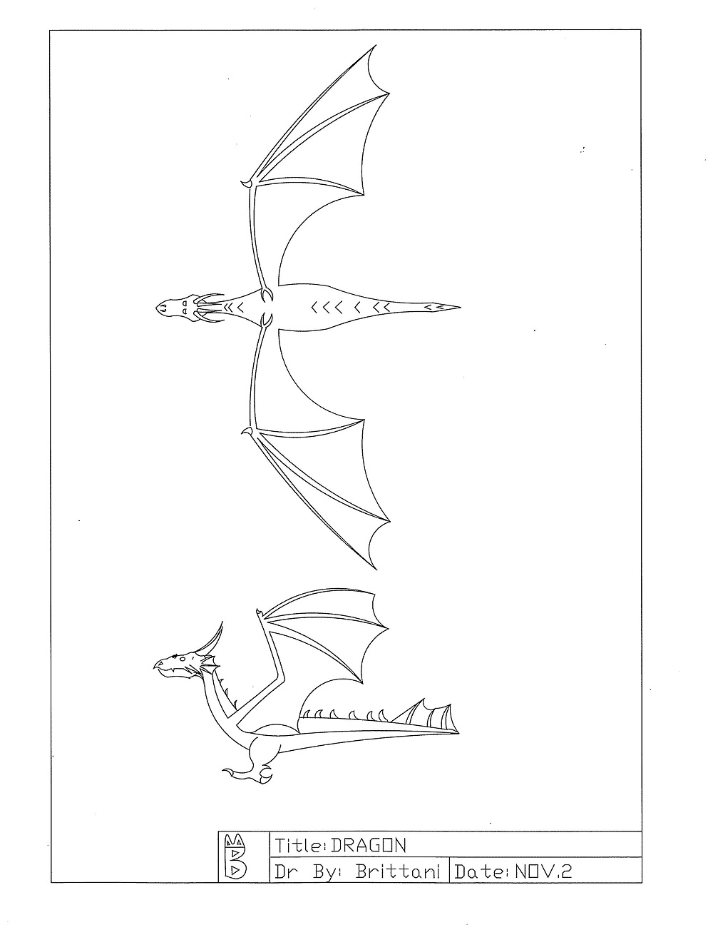
| Hand Sketching is a vital part of Design and Drafting.
Hand sketching is VERY quick and ideal for working out ideas When I fabricate things, I usually sketch my ideas out by hand on paper, or even in chalk on a concrete floor. When the idea and design is a “keeper,” I’ll draw it out in Computer Aided Design (CAD). A large part of this course is brainstorming and design. Developing good sketching skills is vital to your success in this course! Need help sketching something? Ask! I’m more than happy to help. ASSIGNMENT:
|
Top 4
|
||||||||||||||||
OBLIQUE |
|||||||||||||||||
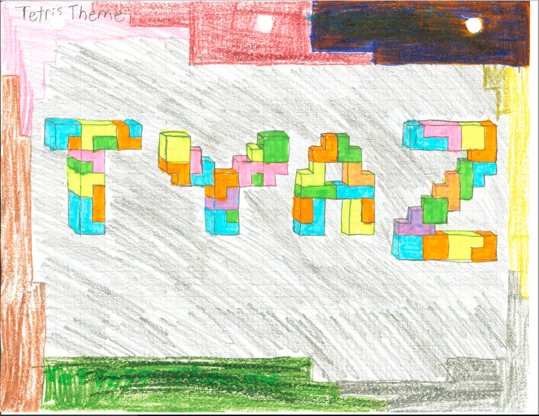
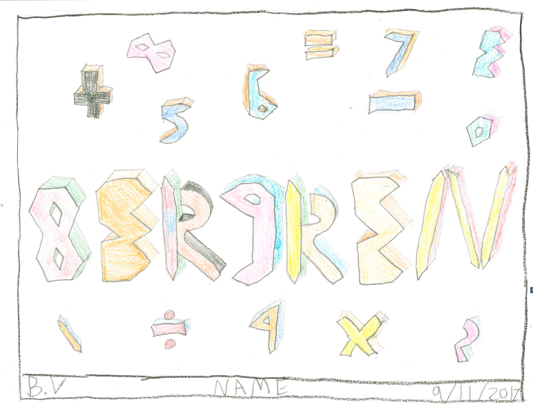
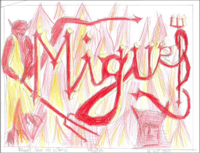
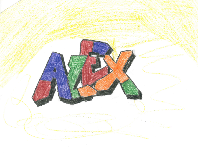
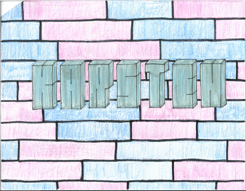
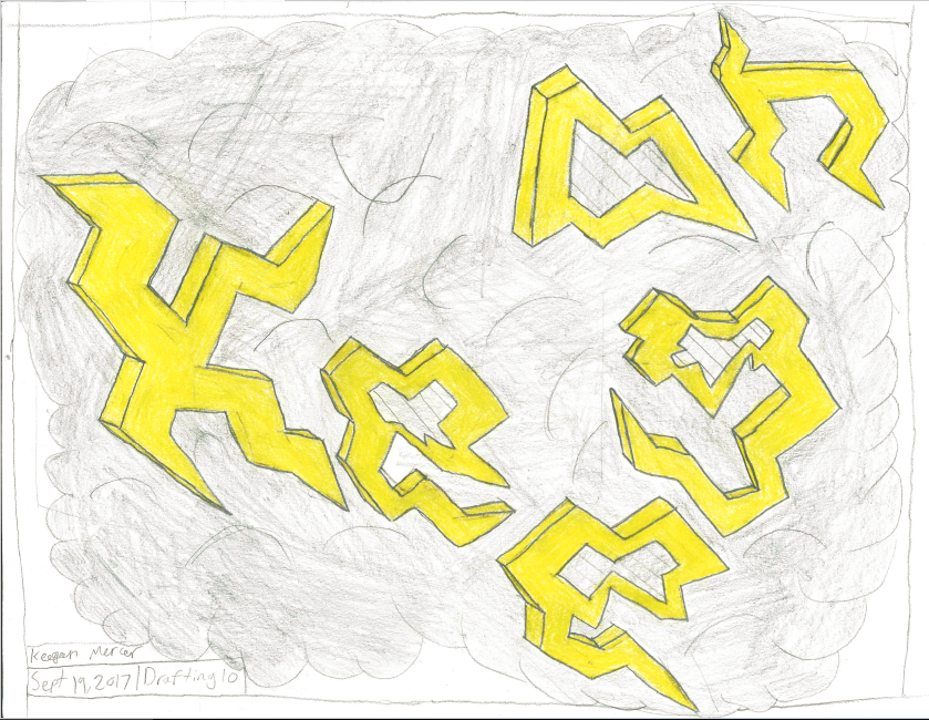
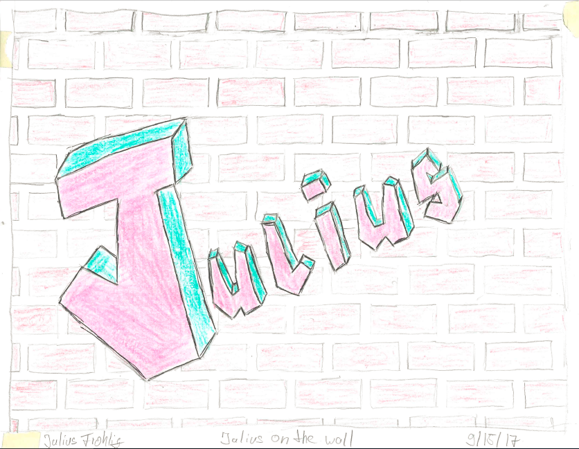
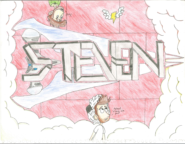
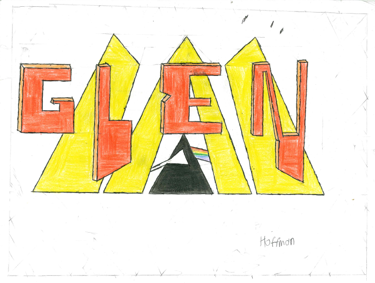
Graffiti Tag |
|||||||||||||||||
| In the previous activity, you sketched how you felt it should look. In Drafting, there are specific “types” of drawings that we use.
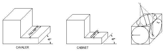
The first “proper” styles of drawing is “OBLIQUE.” I like to think of this as Kindergarten 3D. If you start with a straight-on 2D drawing, add 45° lines to give it some depth and finish it off in 3D, you get a proper Oblique Drawing. These are quite easy to draw. Oblique tends to look somewhat “distorted,” since the lines of depth do not converge on a vanishing point (that is, it doesn’t look like it’s getting smaller the further away it goes). One way to make the drawing look less distorted is to draw the depth half size. Full-depth is called “Oblique Cavalier” and half-depth is called “Oblique Cabinet.” Circles will become ellipses, and are a bit tricky to draw.
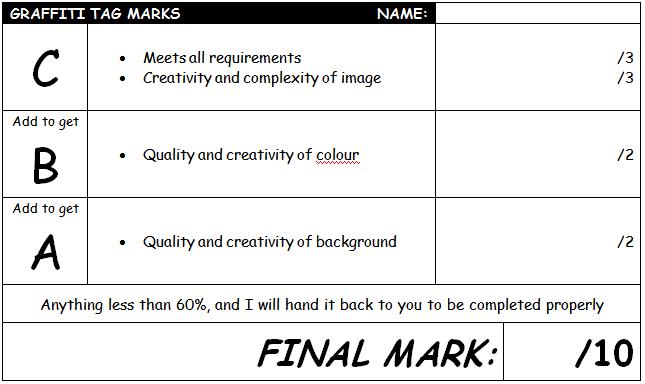
Click for larger image Oblique Drawings are a good choice to show what an object looks like. It is not the best method for production drawings (drawings used to build or fabricate the object). ASSIGNMENT:
Print and mark yourself, then bring your product and mark sheet to your instructor |
 Boring  Awesome Top 10
|
||||||||||||||||
ISOMETRIC |
|||||||||||||||||
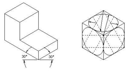
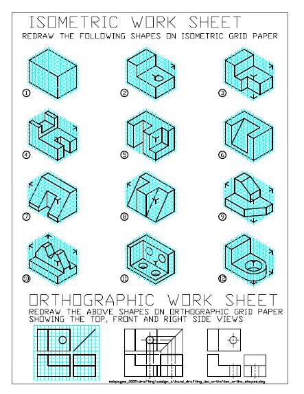
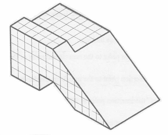
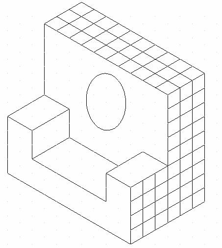
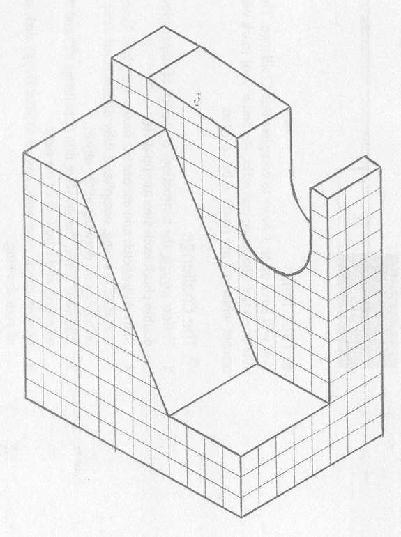
| Isometric Drawing is the second type of pictorial drawing. It is much more realistic looking than Oblique Drawings. An Isometric Drawing looks sort of like an Oblique, except instead of depth coming off a straight-on drawing at 45°, the whole things is sort-of turned 30°
Isometric is still not the best style for Production Drawings, but they are better than Oblique for showing the object are the “distortion” appears to be much less. ASSIGNMENT:
|
 Click for larger image 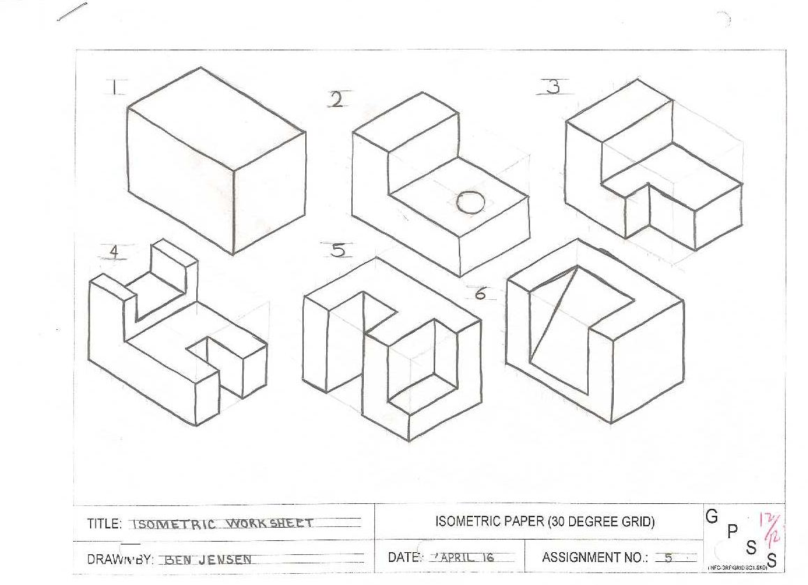 Click for larger image 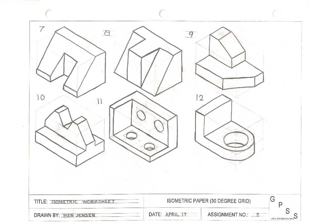 Click for larger image |
||||||||||||||||
THEORY – Equipment |
|||||||||||||||||
| Scales |
|
||||||||||||||||
ORTHOGRAPHIC |
|||||||||||||||||
| Orthographic Drawings are the best for showing all the detail needed to build an object. Almost ALL production drawings are done in Orthographic.
Orthographic Drawings show two or more straight-on views of the object. They do NOT show depth or 3D; every view is straight-on. They usually have a FRONT view, and whatever auxiliary views needed to convey ALL the required Typically, they have three views: FRONT, TOP, & RIGHT SIDE.
These are the most difficult to understand, but once you wrap your head around them, they are pretty easy to draw. It is important to have all your views line up, and the details within the views line up. Make sure the widths and lengths are the SAME on their corresponding views. ASSIGNMENT:
|
Click for larger image 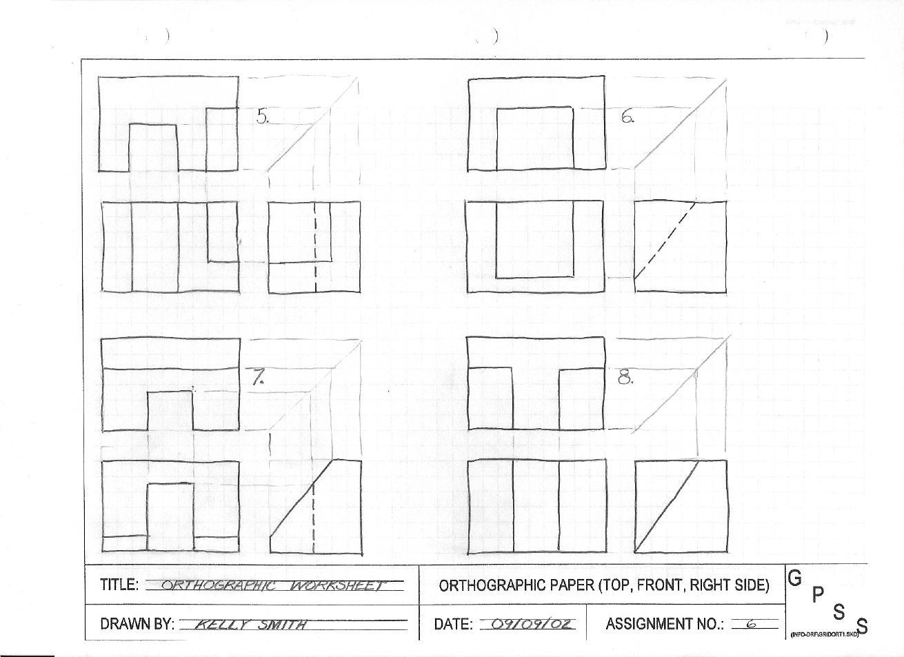 Click for larger image |
||||||||||||||||
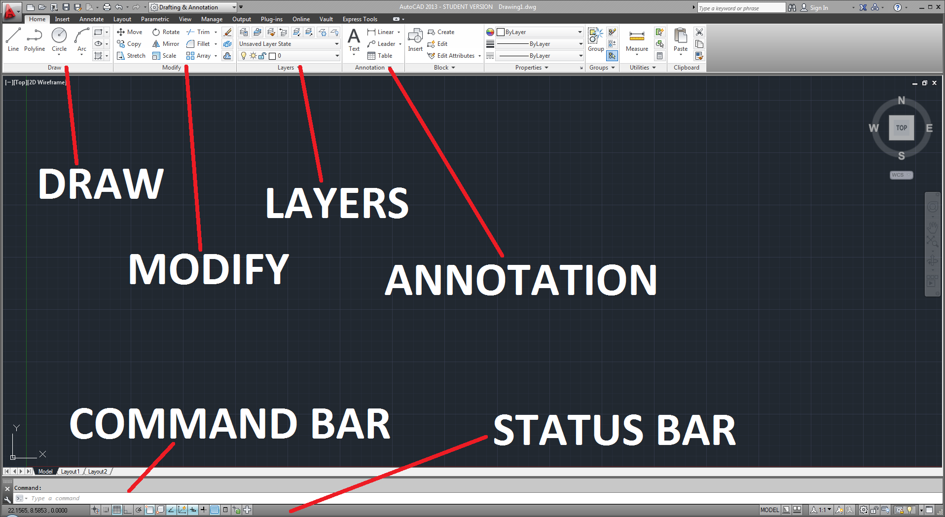
Introduction to AutoCAD |
|||||||||||||||||
| “CAD” stands for Computer Assisted Design. In the bad old days, ALL designs were drawn by hand. While hand drawing is certainly an art, it’s a slow, and dying art.
Today, with computers, designs can be quickly and accurately drawn, and changes can be quickly and easily done (with hand drawings, a significant change might require the entire drawing to be re-drawn!). The current trend is “Solid Modeling,” where components are built on the computer as a 3D object, assembled on the computer, and even tested by the computer before any material is put into production. While there are MANY kinds of CAD software available (we use Fusion360), if you can use ONE, you can use them all – they are all very similar. We will be using AutoCAD, the “industry standard” design software. You can download a copy for yourself for free here: http://students.autodesk.com/. |
|||||||||||||||||
| AutoCAD Basics Intro |
|
 |
|||||||||||||||
| IMPORTANT TIP #1: Explore CAD – It can do more than I can teach you | |||||||||||||||||
| AutoCAD Basics 1 |
|
 |
|||||||||||||||
| IMPORTANT TIP #2: Hit ESCAPE twice to exit a command. “If in doubt, ESCAPE twice out.” | |||||||||||||||||
| AutoCAD Basics 2 |
|
 |
|||||||||||||||
| IMPORTANT TIP #3: Hit SPACE to re-start the last command. Great for repetition. | |||||||||||||||||
| AutoCAD Basics 3 |
|
 |
|||||||||||||||
OSNAPS |
|||||||||||||||||
| So far, you have been using SNAP to create your drawings. SNAP is handy as long as your drawing has line segments that match your snap setting. But, what if you need a line not 50mm, but 51.875? How do you set snap for that?
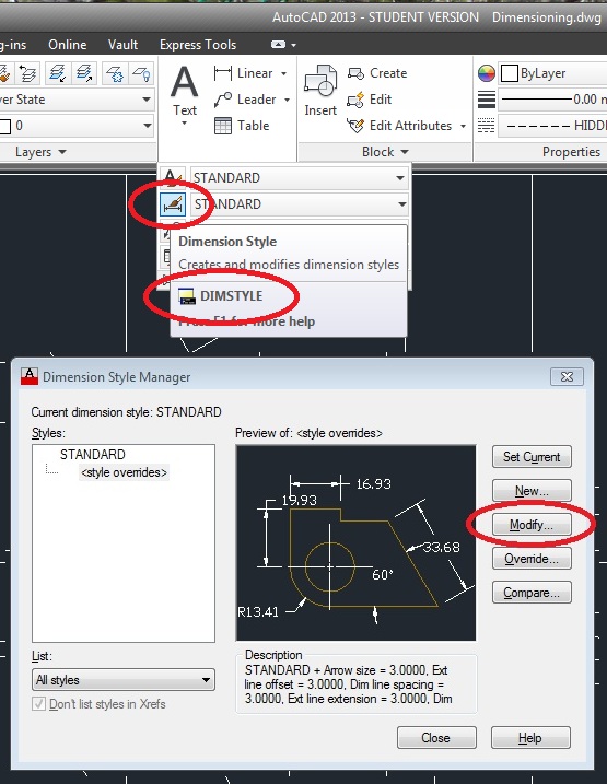
OSNAPS are special snaps that allow you to snap to certain parts of your ENTITY (drawing), instead of GRID. Some OSNAPS are “on” by default. You can open and change the defaults:
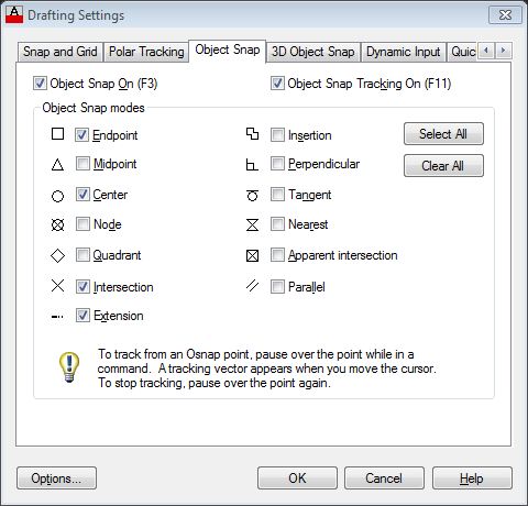 Using OSNAPS makes drawing in CAD much, MUCH MUCH faster and EASIER – from now on: DO NOT USE SNAP; force yourself to OSNAP. IMPORTANT TIP #4:Get used to using OSNAPS – your drawings will go MUCH faster. |
|||||||||||||||||
LAYERS |
|||||||||||||||||
| IMPORTANT TIP #5: GET USED TO USING LAYERS – THEY SPEED THINGS UP DRAMATICALLY
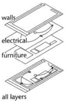
What are Layers?
Layers are like drawing on clear plastic where each layer of plastic is a different layer of drawing When and Why are Layers Used? When drawing in CAD you are always drawing on a layer – it may be the default layer. Each layer has color, linetype, lineweight (thickness), and plot style that can be set You can use layers to organize your drawing into groups of objects such as linetypes (centerlines, object lines, etc.) or in the case of home design you can have layers like walls, electrical components, plumbing, appliances, roof, furniture, etc. You can turn certain layers off (or freeze them) when you no longer need them or when you do not want to print (plot) that layer with the rest 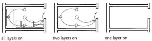 Type LA to enter the Layer Properties Manager – it will pop up on the left side of your screen. Right Click on the right hand pane to create a new layer 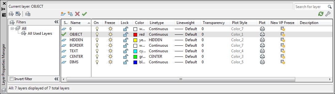 You can also change the linetype and line Color as appropriate You can turn layers on or off, freeze or thaw, lock or make them current 
|
|||||||||||||||||
TITLE BLOCK |
|||||||||||||||||
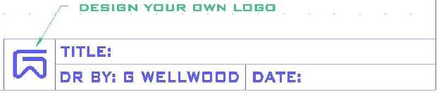
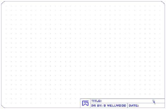
| Title Block | You will be using ENTITY SNAP and LAYERS in this activity
Every drawing you do will need a title block. Instead of drawing a new title block for every drawing, you can draw ONE, and then import it, complete with all your layers, colours, line types, name and everything already loaded. AutoCAD even allows us to add the Drawing Title, Date, and any other information we want into our title block so all the text looks awesome (this is SO easy, and saves us SO much time). ASSIGNMENT: TITLE BLOCK TUTORIAL You will be designing your own awesome LOGO to make your title block uniquely yours! SCALE YOUR TITLE BLOCK TO FIT EACH DRAWING – NEVER SCALE YOUR DRAWING TO FIT THE TITLE BLOCK!! |
|
|||||||||||||||
MASTERING CAD |
|||||||||||||||||
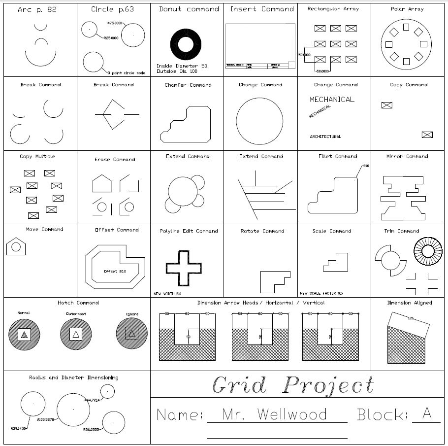
| Grid Project |
|
 |
|||||||||||||||
GETTING FASTER |
|||||||||||||||||
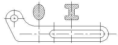
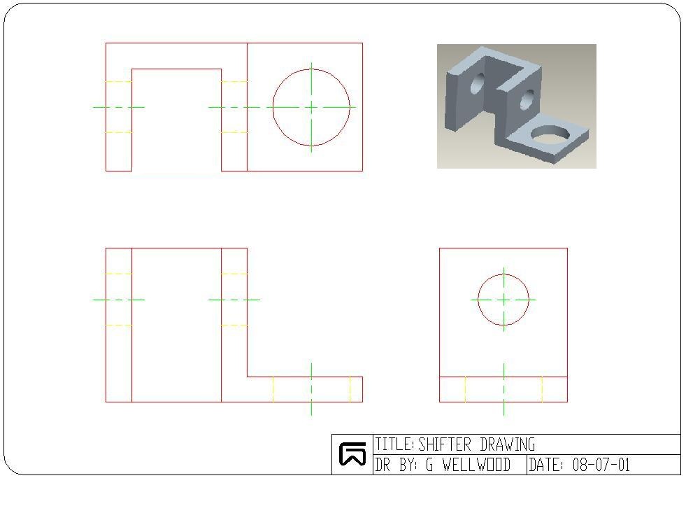
| Shifter Tutorial | This tutorial shows you step-by-step, the quickest, most accurate way to draw an Orthographic Drawing in CAD
Offset will be your friend here, as well as learning some quick-key shortcuts using X,Y co-ordinates Follow the TUTORIAL step-by-step I can do this drawing in less than 10 minutes. Can you? |
 |
|||||||||||||||
| IMPORTANT TIP #6: Use OFFSET and TRIM as much as possible – it speeds things up! | |||||||||||||||||
DESIGN |
|||||||||||||||||
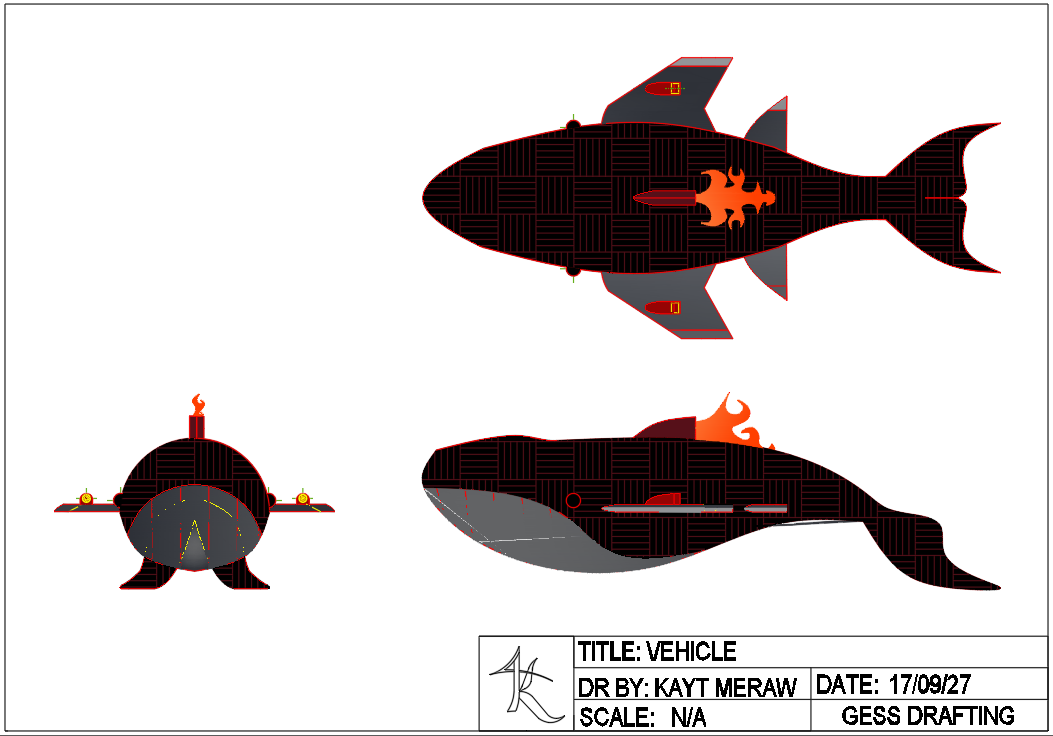
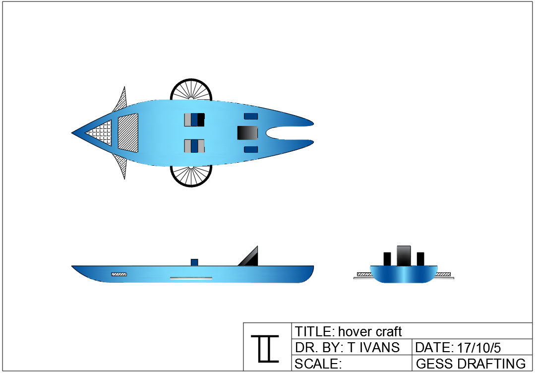
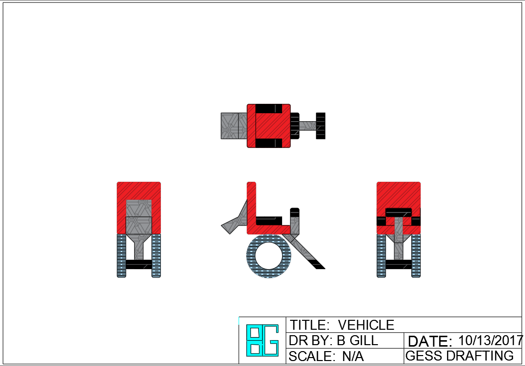
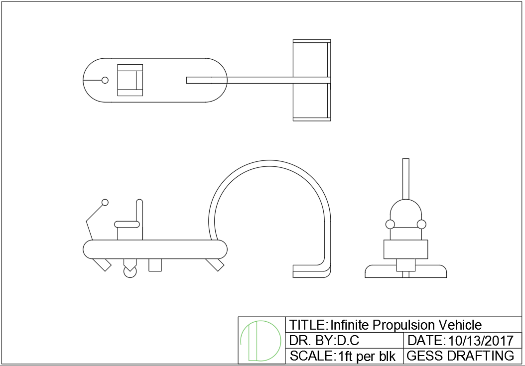
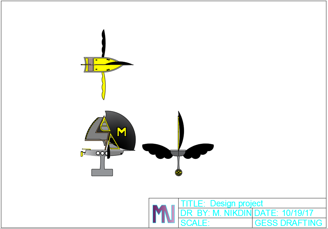
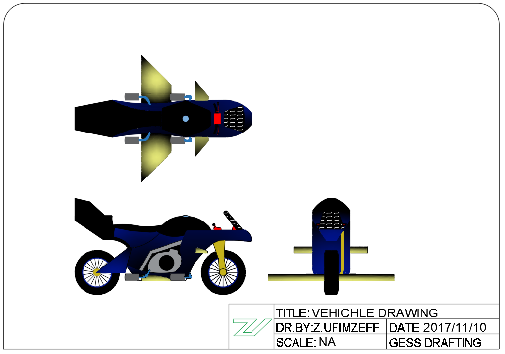
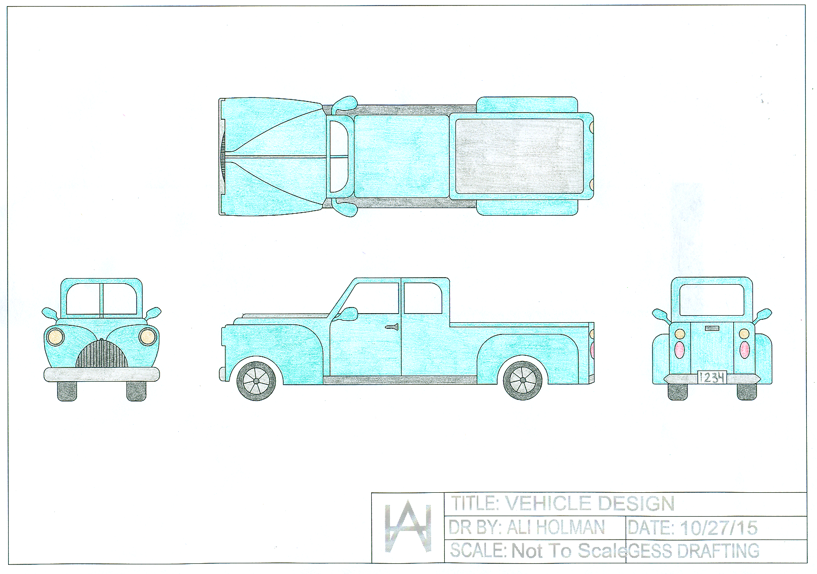
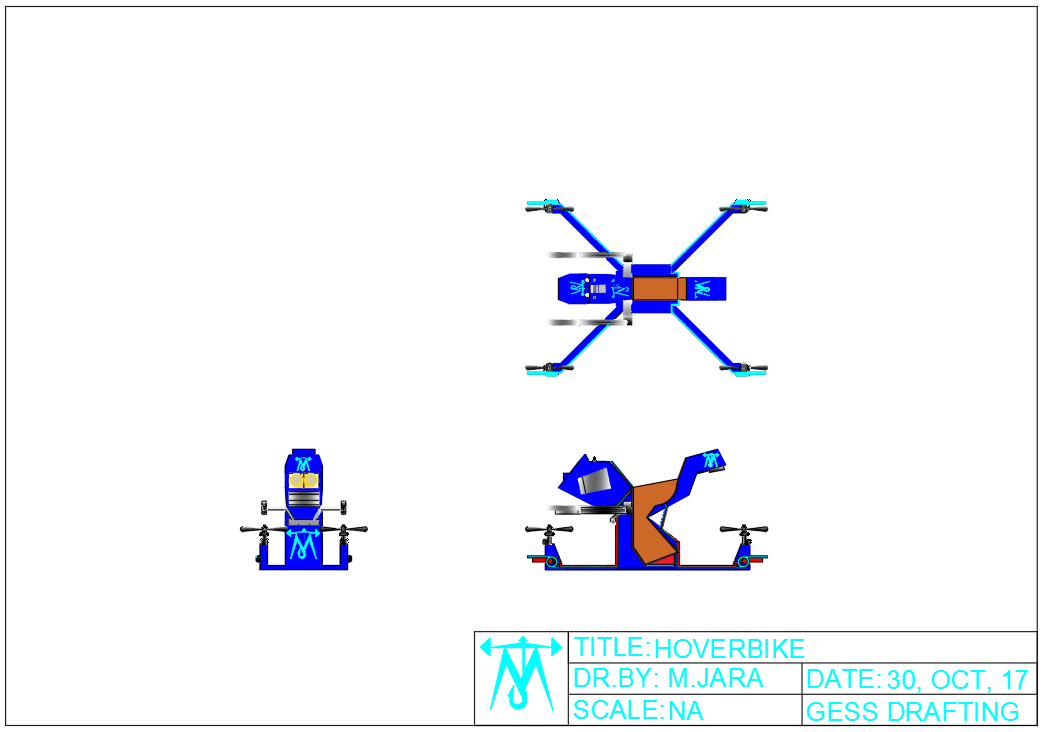
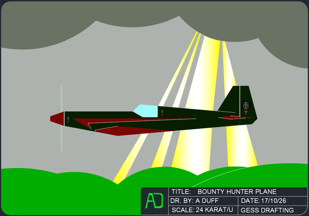
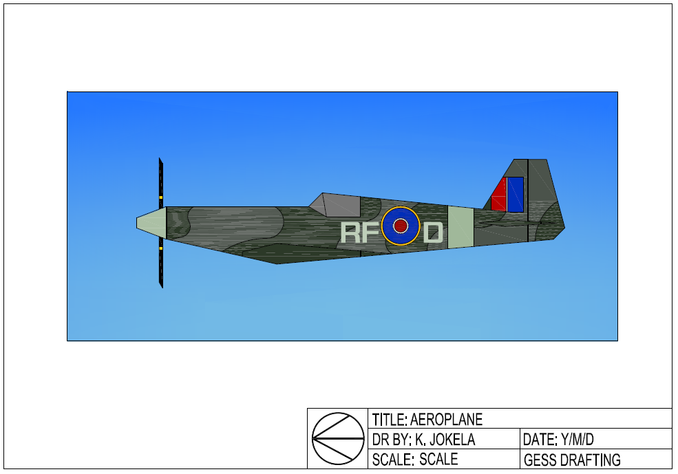
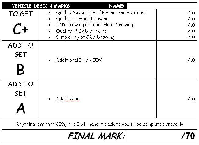
| Vehicle Design | In this activity you will be design your own unique vehicle draw it orthographically
Orthographic Drawings are best suited for complex designs and fabrication as they show the most specific detail You will be designing, drawing and printing a picture of unique vehicle. You may choose from the following:
Your design must show the SIDE and TOP views. Your design MUST be VERY detailed Use magazines, books or the internet to research some designs, but YOU must come up with YOUR OWN idea!
 |
Most Creative
|
|||||||||||||||
DIMENSIONING |
|||||||||||||||||
|
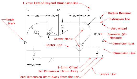
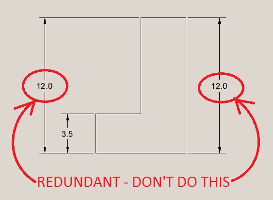
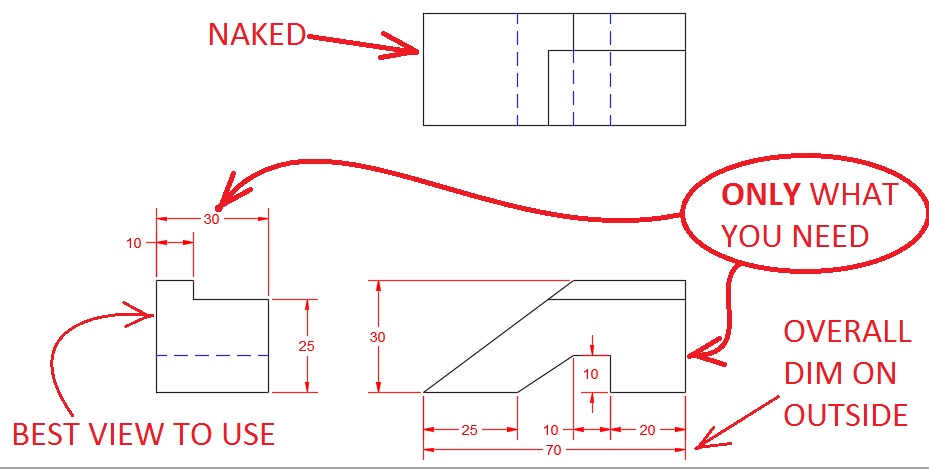
Dimensioning is one of the MOST IMPORTANT parts of Drafting – LEARN THIS! ONLY show the dimensions you NEED to show to BUILD the object – NOTHING MORE DO NOT DIMENSION EVERY SINGLE LINE THAT EXISTS! – Be lazy! Only the work you HAVE to NO REDUNDANT DIMENSIONS (never dimension the same thing twice!) AS MUCH AS YOU CAN on one view, WHATEVER YOU NEED on another view, and the LAST VIEW IS NAKED All Manufacturing and Fabrication industries depend on Drafting. Without Drafting, nothing can be manufactured. The “drawings” that companies use to “Work” from are called “Working Drawings.” A Working Drawing must have enough A Working Drawing must include:
ASK YOURSELF – “Can this object be built without further instructions?” |
|||||||||||||||||
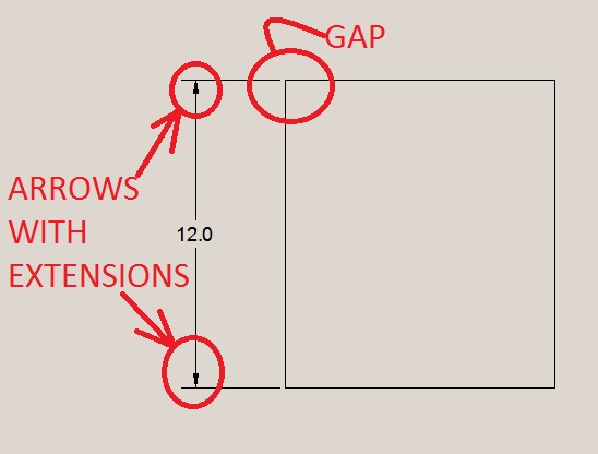
| Dimension lines have ARROWS pointing to EXTENSION LINES
Extension Lines DO NOT touch the object |
 |
||||||||||||||||
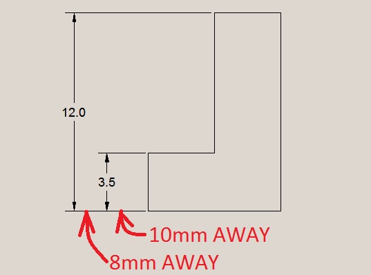
| Dimension lines start 10mm from the object and then 8mm apart from each other
Overall dimensions are OUTSIDE smaller dimensions and SHALL NOT CROSS |
< |
||||||||||||||||
| Do not duplicate dimensions
Do not duplicate dimensions Do not duplicate dimensions Do not duplicate dimensions |
 |
||||||||||||||||
Dimension on the CLEAREST VIEW, usually:
|
 |
||||||||||||||||
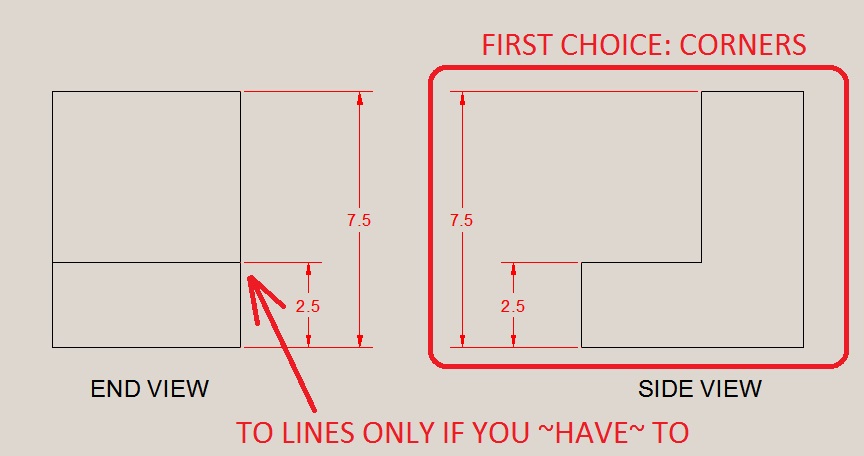
| Dimensions go BETWEEN THE VIEWS
Dimension to CORNERS is better than LINES DO NOT Dimension to hidden lines |
 |
||||||||||||||||
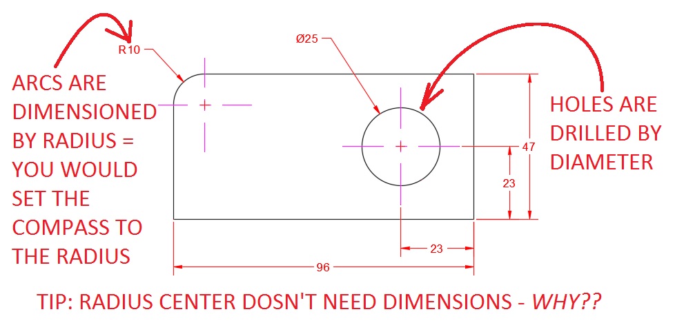
| ARCS are dimensioned by RADIUS (you use a compass to draw them)
HOLES are dimensioned by DIAMETER (you use a drill to cut them) YOU MUST DIMENSION HOLE CENTERS!!! (Where is the hole located??) |
 |
||||||||||||||||
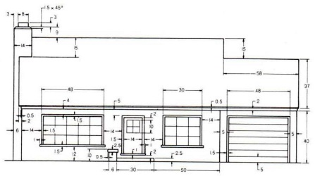
ALL-IN-ONE-EXAMPLE:
|
|||||||||||||||||
Part I
 Show your instructor for marks!
DIMENSIONING DRAWING IIPart II
Show these three drawings to your instructor for marks!IMPORTANT TIP #7: Dimensioning must be CLEAR and EFFICIENT – Make it CLEAR and EFFICIENT This allows you to very specifically and accurately (and quickly!) lay out lines and locations with absolute The CAD world uses the Cartesian Grid System. Remember in Math when you graph, with x,y and 0,0 is at the bottom 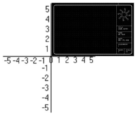 Angles are done using Polar Co-Ordinates. They are measured in the graph starting horizontally right (0°) and 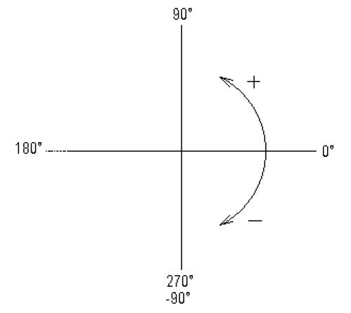
Use these methods of drawing in your assignments from now on – they will really really improve your speed in CAD. |
|||||||||||||||||
CO-ORDINATE ENTRY |
|||||||||||||||||
MAPLE LEAFFollow: TUTORIAL – Maple Leaf and SHOW YOUR INSTRUCTOR FOR MARKS
 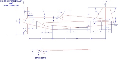 Click for larger image
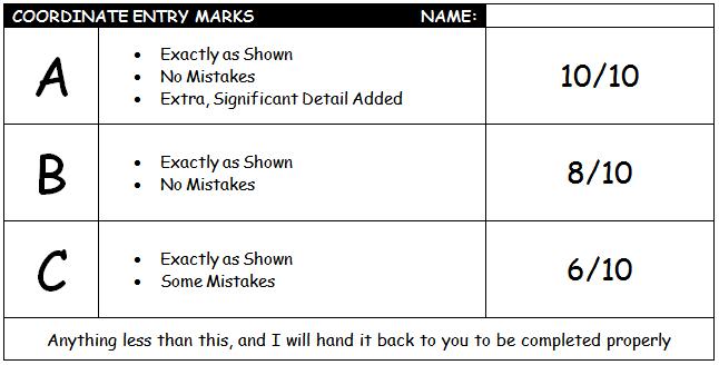 Same mark sheet for both House and Plane – Have your instructor mark this ON SCREEN 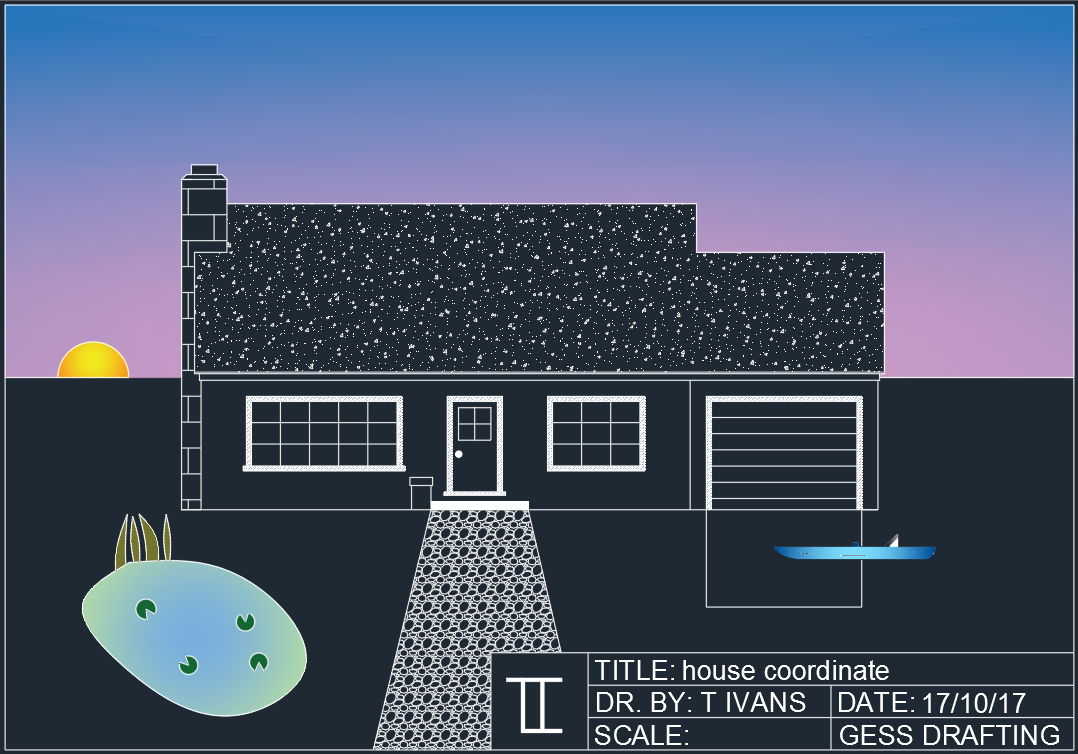 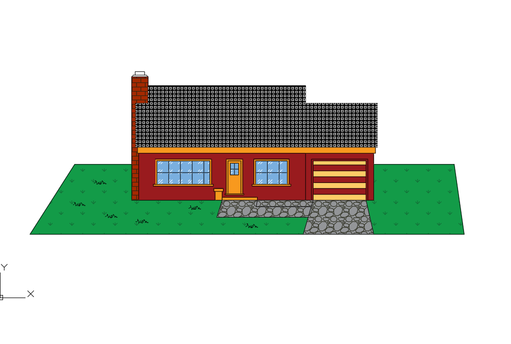 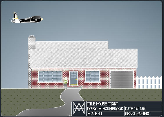 
IMPORTANT TIP #8: Use COORDINATE ENTRY as much as possible – it speeds things up! |
|||||||||||||||||
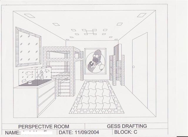
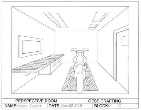
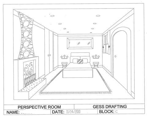
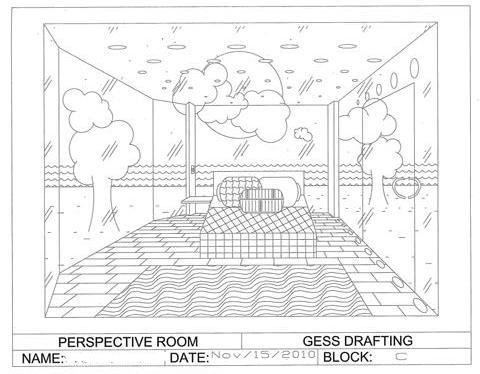
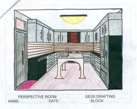
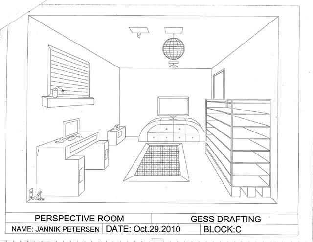
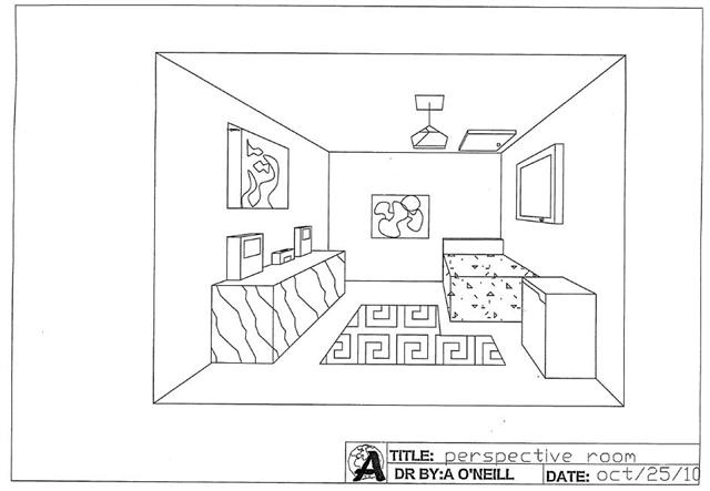
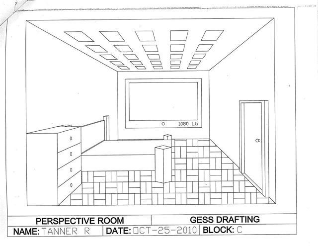
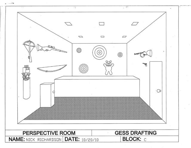
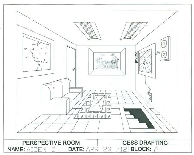
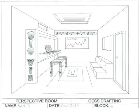
ROOM PERSPECTIVE |
|||||||||||||||||
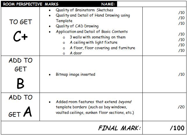
In this activity you design and draw a room using one-point perspective. Perspective Drawings are best suited for presenting ideas and designs as they show the most realistic appearance. These drawings use one or more vanishing points to make objects get smaller the further they are away from us. 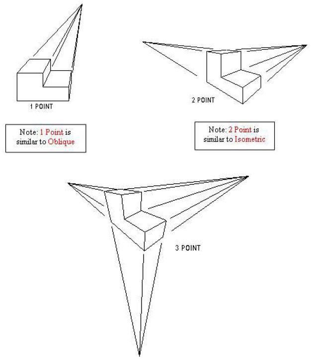
|
|||||||||||||||||
SECTIONING |
|||||||||||||||||
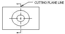
| Sectioning. If an object so complex that a typical “outside view” drawing like you have been doing does not show enough information, or there are so many hidden lines that the drawing no longer makes sense, we want to show what’s going on inside….This is called a Section View.A SECTION VIEW looks like we fired up a chainsaw to show what is going on inside.
A section view starts as a typical drawing, except it is drawn as if a portion has been cut off and removed to make things more visible. A section view must tell the viewer WHERE the cut is taking place and WHICH way to look. This is called the |
|||||||||||||||||
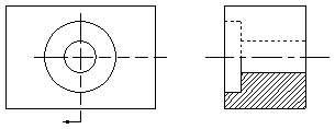
The Cutting Plane Line
Once you set the Cutting Plane Line, you can then “cut off” the material to show what’s inside. |
|
||||||||||||||||
| HOW you make your cut depends on WHAT you need to show.
There are six types of Section Views, used wherever they BEST show the MOST information. |
|||||||||||||||||
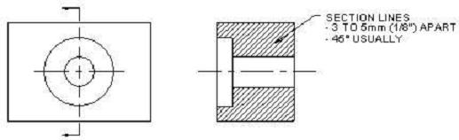
The Full Section
|
 |
||||||||||||||||
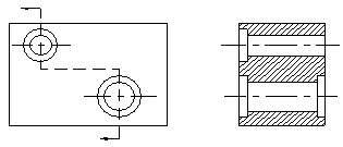
The Offset Section
|
 |
||||||||||||||||
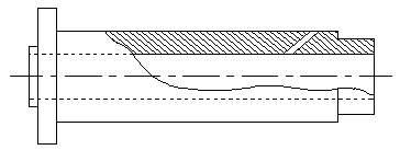
The Half Section
|
|
||||||||||||||||
The Broken Out Section
|
 |
||||||||||||||||
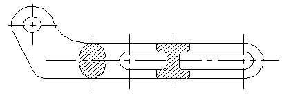
The Revolved Section
|
 |
||||||||||||||||
The Removed Section
|
 |
||||||||||||||||
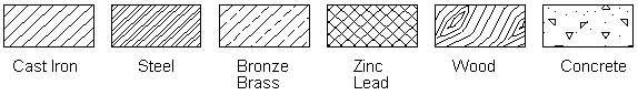
Section SymbolsTo further clarify the object has been sectioned, we need to assign some crosshatching (or “fill”). Different hatch patterns are used depending on what the material is that we are sectioning. Here are some common types of hatch:
|
|||||||||||||||||
Sectioning Activity
 |
|||||||||||||||||
PACKAGING DESIGN |
|||||||||||||||||
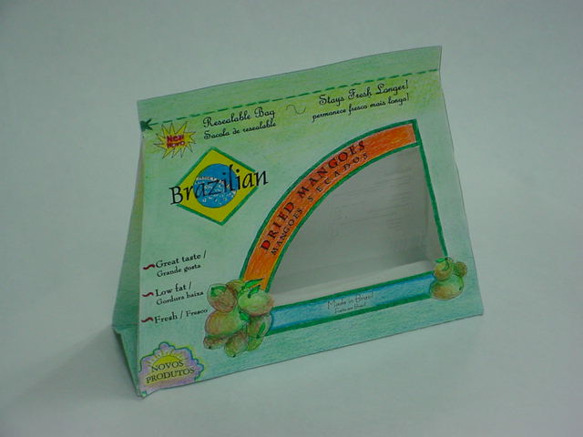
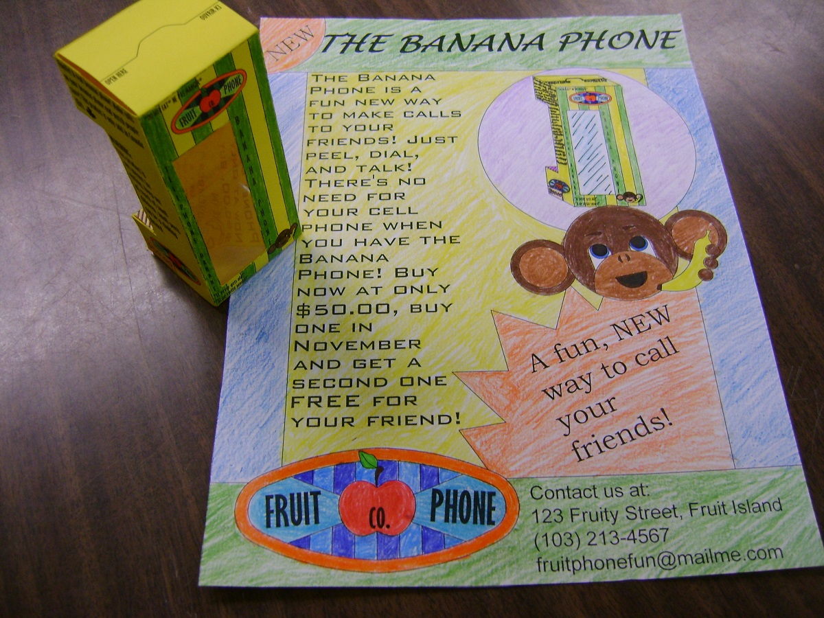
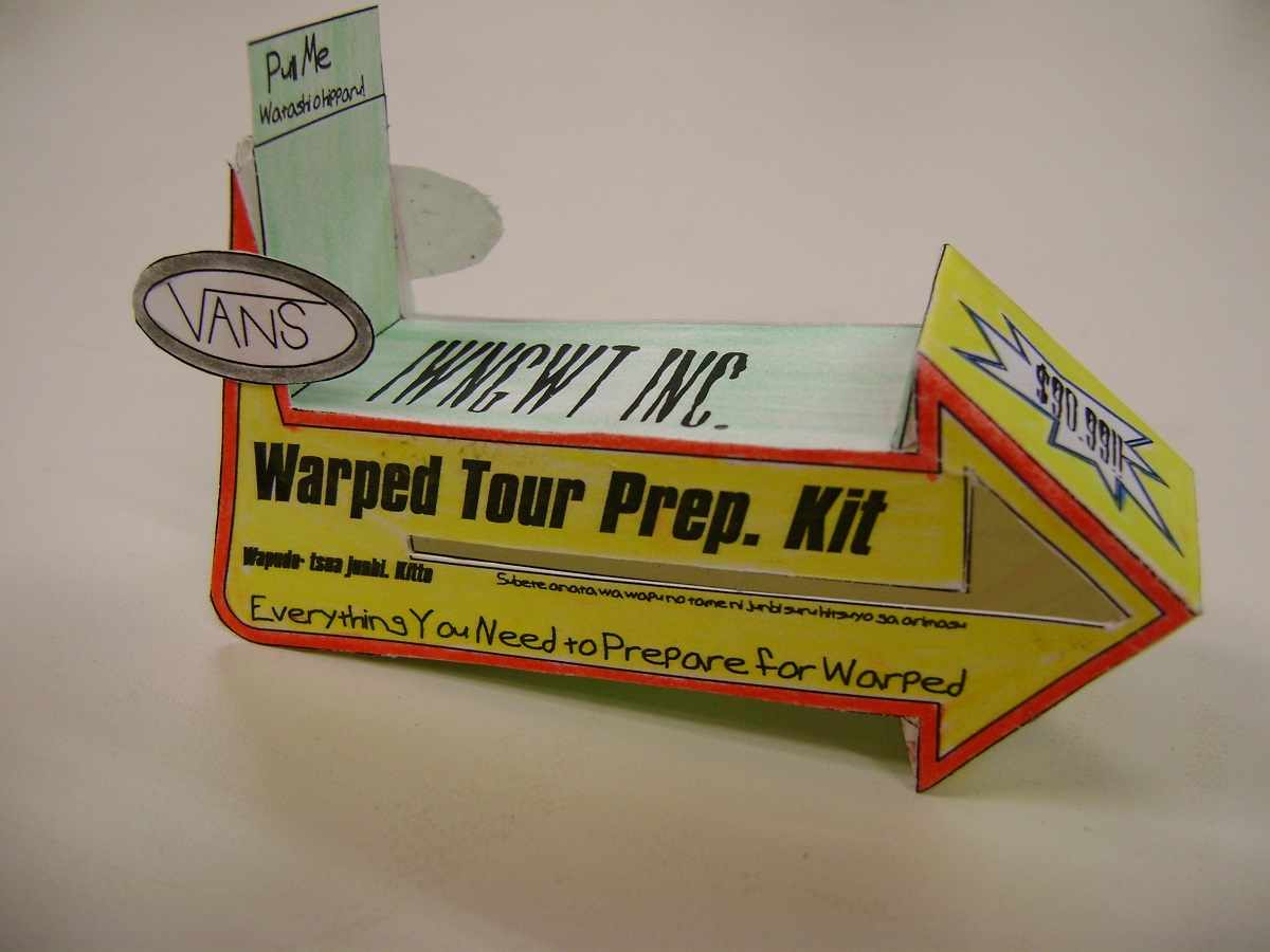
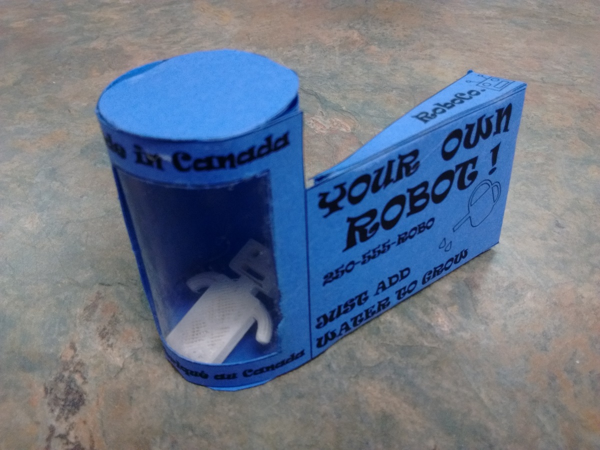
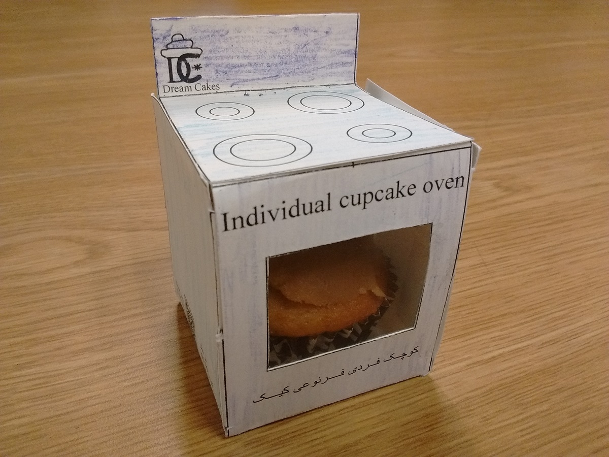
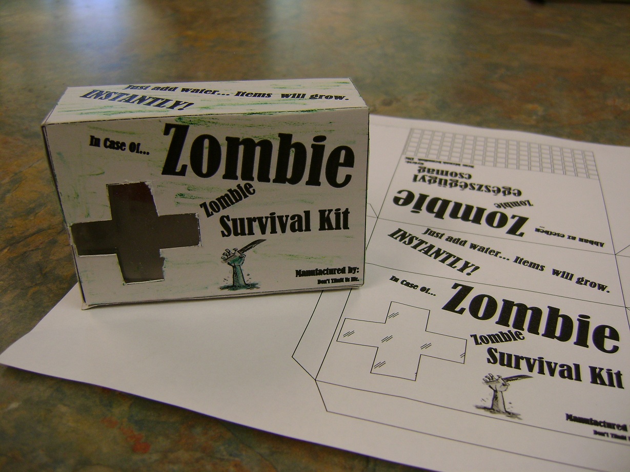
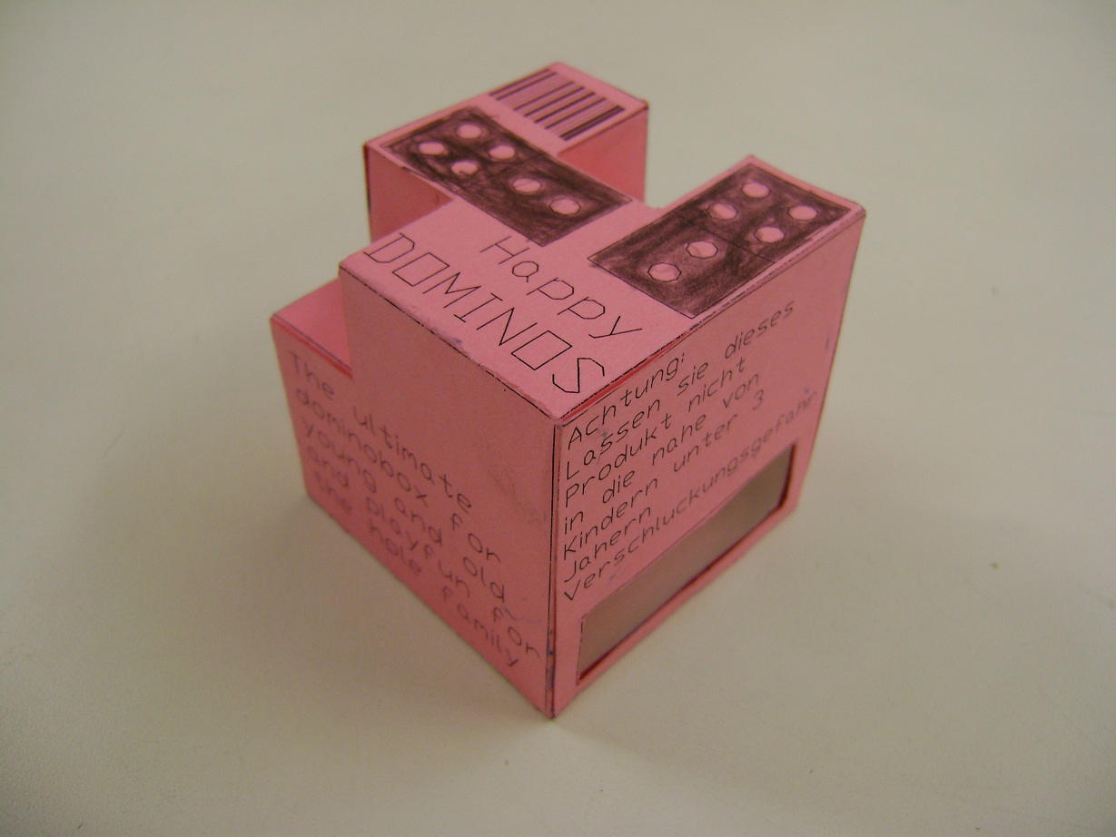
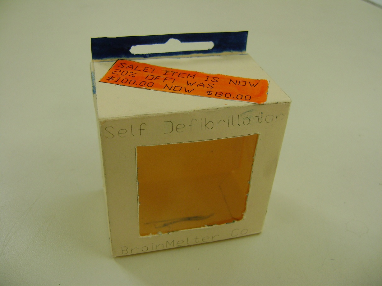
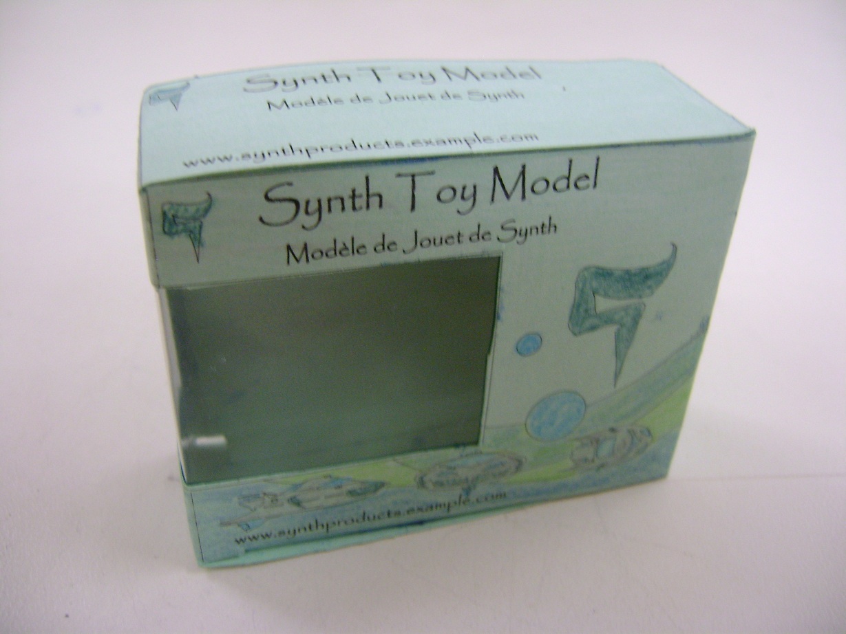
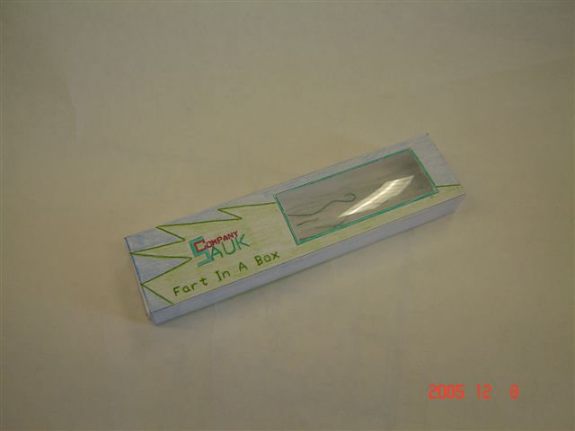
| One area in product marketing that can make or break a product, is the packaging. Packaging enhances the sale of a product. It is also a very big business. Industries hire designers, fabricators and artists to find the perfect balance between artistry and function.
The design “tool” of choice in most cases is a CAD program like the one you are using for this challenge. In this activity you will design, model and market a Product Packaging. What makes this even more of a challenge, is that you must design the package such that it can be printed and folded together from ONE piece of card stock. This kind of design is called a “Stretch Out.”
Your finished Product Packaging must include the following:
Top 20
|
|||||||||||||||||