
[Drivetrain] [Brakes] [Suspension] [Steering] [Electrical] [Emissions]
QUESTIONS – Electrical |
||||
We are going to cover:
This is a big unit – try to work quickly and do not waste time. As always – if something seems unclear, it probably is – so ask me for clarification (then I can make it more clear for others)
|
||||
BASICS |
||||
|
Almost everything in the modern automobile is electrical or electronic. In the bad old days, the only things electric were the lights, the ignition, and the charging system. Today? EVERYTHING is touched by Electronics. A good mechanic will seek to understand electrical. Without a good basic understanding of electrical, YOU ARE HOOPED. CLASSROOM LESSON: MrWELLWOOD’S PICKLE THEORY!
Key Phrase: “Electrical is all about the Intentional and Directed Flow of Electrons to Perform Work.”
The CIRCUITElectricity is about the DIRECTED FLOW of electrons. Electrons need to FLOW through a CIRCUIT. A CIRCUIT is a COMPLETE PATH for ELECTRICITY to travel through. It usually consists of: A source of Electricity (battery – the Battery PUSHES the electrons with VOLTAGE) A path for Electricity (wires – the wires CONDUCT electricity) A load for Electricity (the component – RESISTANCE in the component changes the FLOW of electrons into HEAT or LIGHT or MOTION) The biggest causes for problems in electrical circuits are broken paths, or bad connections.
|
||||
THE SOURCE – WHERE THE ENERGY COMES FROM |
||||
|
The electrons need to come from somewhere. In your house, it comes from your 120 Volt wall socket. In a car, it comes from the 12 Volt battery under the hood. The car battery uses a chemical reaction to produce electrons. As electrons are used up, the battery goes dead. Re-charging the battery renews the chemical reaction. All cars have a method of re-charging the battery while in use. The VOLTAGE of a battery is its ability to PUSH the electrons. Generally, higher voltage can push a lot harder. But the power of a circuit isn’t entirely about the Voltage, or “Push.” It also depends on how QUICKLY the electrons can move with that push. The speed the electrons move at is called CURRENT, and it’s measured in AMPERES or Amps for short. Don’t think a 12V car battery is less than your 18V Cordless Drill battery: A car battery can provide its 12V VERY QUICKLY (the SPEED of electricity is its CURRENT, measured in AMPERES). Quick enough to burn you very badly. An 18V drill battery may provide 6 or 8 Amps of current. The 12V battery in my truck is 900 Amps. My welder at home only puts out 200Amps. STATIC ELECTRICITY can be hundreds or even thousands of volts, but it won’t kill you because it has LITTLE TO NO CURRENT. NEVER wear rings or metal watches around a battery!!!NEVER rest tools or parts on a battery!!!
Voltage is the PUSH to move the electrons (measured in Volts). The higher the Voltage, the higher the PUSH. The SPEED the electrons move is called CURRENT (measured in Amperes). Current is what kills you.
|
||||
THE PATH – HOW THE ENERGY GETS THERE |
||||
|
All electrical circuits in the automobile use two parts to make the path. WIRE: multiple-strands (“stranded”) for flexibility, insulated for protection, and sized according to the amount of electricity it has to carry (lots of electricity = large size wire) CHASSIS: Use the metal chassis to return all the electricity to the negative side of the battery. This cuts down on the amount of wire needed, and like, dude – the metal’s already there. The Negative Side of the circuit, and the chassis, is called “ground” (or “Earth” in the UK).
|
||||
THE LOAD – ENERGY PUT TO USE |
||||
|
The load is what USES the electricity. It could be a starter, a light, a horn, an ignition coil, a stereo or a ground-to-air missile launcher. The load is what puts electricity to work for us. Most loads have a measurable RESISTANCE. Resistance is measured in Ohms. This can be measured with an Ohmmeter. A load with high resistance resists the flow of electricity a lot – the electricity will travel slowly (low current). A load with low resistance allows the electricity to travel through it very fast (high current).
|
||||
LET’S GO OFF ON A TANGENT…. |
||||
|
A basic car stereo shown here has a SOURCE (the deck itself), a CIRCUIT (the wires) and a LOAD (the speakers).
POWER SOURCEThe stereo needs to get its electricity from somewhere – the deck runs off the 12V battery. A wire is run from the battery positive (though usually through the key switch) to the deck. The wire must be large enough that it will not melt from the the flow of electricity (high electrical flow produces heat). To save wire, we will connect the negative connection (called “Ground”) of the deck to the car chassis, and connect the car chassis to the negative post on the battery.
AMPLIFIERSThe deck acts as the SOURCE for the speakers, but the deck can provide only so much electricity. It has limits based on the circuitry inside, and the voltage of the battery. Loud music needs LOTS of current. we need LOTS of electricity to flow. The flow of electricity is called CURRENT. Current is our friend when it comes to power. We want lots of power. We want lots of flow. We don’t have enough, so we want to amplify what we have. We need to add an amplifier. An amplifier takes the SIGNAL from the deck, and adds higher voltage to it. It takes the 12V and through fancy circuitry can raise it to, say, 100V. This will require some pretty hefty wiring. A 1000W amp will need 4ga wire to do this!
SUBWOOFERSBass frequencies are difficult for us to hear, so we must make them louder. We need a BIG speaker that is designed for this called a woofer. Subwoofers are designed to play very low frequencies, especially ones lower than you can hear, but that you can feel. Low frequencies draw a LOT of current, which need a BIG amplifier and BIG wiring. If we don’t use large enough wire, the high current can create enough heat to melt the wire and cause a fire! Subwoofers draw so much power, that sometimes the Battery cannot provide enough voltage fast enough. Adding a Stiffening Capacitor to the system allows unneeded voltage to be stored and drawn quickly when it IS needed. Some stereo shops suggest that a stiffening capacitor isn’t really needed, but that doing “the big three” is. The Big Three: LARGE positive battery cable to the alternator (so the charging system can get current easily to the battery) LARGE negative battery cable to the chassis AND engine block (so the current can return to the battery easily) LARGE positive battery cable to the starter (this would help the starter for sure, but some cars tap into the starter cable to feed everything inside the car)
LOWER RESISTANCEIf one subwoofer is good, two much be better. But there is a right way and a wrong way to hook them up. Loads resist the flow of electricity. This can be measured and is called (oddly enough) Resistance. It is measured in Ohms (?) A typical subwoofer is rated at 4? resistance. If we can replace it with a lower resistance subwoofer, say 2?, the electricity will travel through it faster (higher current). Since the resistance is HALF, the current will travel TWICE as fast – the subwoofer will want to draw TWICE as much current, and (assuming nothing melts or burns to the ground) the amp will provide TWICE the power and the speaker will play TWICE as loud! Cool! While the 4? subwoofer might have received 1000W of power, the 2? subwoofer would now receive 2000W of power. Booyeah! I don’t know of anybody who makes 1? subwoofers. But there is a way to get it through some crazy wiring: SERIES CIRCUITSJust like a TV Series is one show after another, and a Serial Killer works one after another, a Series Circuit has a “Series” of loads, one-after-another. We could take two 2? subwoofers and wire them in series, forcing all the electrons to flow through one subwoofer and then through the next subwoofer. Like two kinks in a garden hose, this would slow down the current considerably. These two subs would act like a single 4? load. If your amp can only handle a 4? load, this is one way to make it survive. But keep in mind that if one sub dies, you get no sound at all.
Two 4? subwoofers in Series = 8? load – half the power, but your amp loves it (easy work) PARALLEL CIRCUITSYou know how the halls are crowded? If you could split yourself in half, or into thirds, or even more, the thinner portions of yourself could zip through the crowded halls way faster. Electricity is going to do the same thing here with multiple paths. One subwoofer has one path for the electrons to travel through. Electricity splitting between two subwoofers (“Parallel”) can split up the electrons so half goes through one, and half goes through the other. Splitting the electrons up like this makes them travel faster; more current. Current is our friend when it comes to power. Two 2? subwoofers wired in parallel like this will act as a 1? load because it’s EASIER for the electricity to get through each subwoofer. Assuming the amplifier above (1000W into 4?) can handle the current without going completely Chernobyl on us, we can have 4000W of power! Sadly, few amps can do this. Few affordable amps, anyway.
Here’s me in a video explaining it:
CIRCUIT PROTECTIONSpeaking of Chernobyl, did you notice the FUSE in the top right of the stereo diagram?
All circuits need some kind of protection for the unexpected. Let’s say while testing your stereo, you accidentally connect the two speaker leads (+ and -) together. The amp would see NO resistance. The amp would try to provide ALL the current it can possibly muster, and draw as much current from the battery as it possibly can. This might be more current than the circuit/wires/amp is designed for. Something will either melt catch fire. Or let’s say you didn’t use a rubber grommet for the wires passing through the firewall (bad, bad, bad move), and the sharp edge from the hole cuts through the amp power cable and connects Battery Positive directly to Ground (the chassis). The battery will try to dump everything it can into that grounded circuit, and you’ll wish you had brought a fire extinguisher. A fuse is designed to be “the weak link.” It is designed to burn open if too much current flows through it.
There are a few tips about fuses:NEVER replace a blown fuse with a higher rated one – FIX THE PROBLEMALWAYS keep the fuse as close to the battery as possible
TROUBLESHOOTINGEvery circuit you have in an automobile will be diagnosed the same way. Every circuit has a SOURCE, a CIRCUIT (PATH), and a LOAD. These are the things you need to investigate: Is the voltage getting to the component (the load)? (check with a voltmeter) Is the component getting a good ground? (check with a voltmeter or ohmmeter) Does the component work? (check resistance, or apply voltage to it) “Intermittent” problems are almost ALWAYS electrical, and almost ALWAYS bad connections or broken wires. “Possessed By The Devil” problems are almost always GROUNDING issues. Without a proper ground, your circuit may ground through OTHER things – resulting in some very weird stuff happening…. Cool Story Bro: To get my Lotus 7 Replica through its inspection to be registered as a new vehicle, I needed to have Daytime Running Lights (DRL). I studied the wiring harness, and determined if I tapped into a certain spot in the wiring, I would have headlights running all the time. I did, and it passed the inspection. What the inspector didn’t discover, was if you hit the high beams, the cooling fan would turn on – the high beams were grounding through the cooling fan circuit.
Voltage Drop TestProbably the best method to test electrical problems is to do a VOLTAGE DROP TEST. Connect a voltmeter ACROSS the COMPONENT or CONNECTION or CONDUCTOR to be tested. Activate the circuit. Any voltage measured is the voltage being used. There should be NO voltage being “lost” in wires, or at connections. ALL the voltage should be being used by the component. If you have 12V at the source, and 9V at the load – where did the rest go? That’s where your problem is!
|
||||
THE BATTERY |
||||
|
You can make a simple battery by using acid and two dissimilar metals. That is all a battery is. You can even make a battery out of a potato, a lemon, or a pickle. Anything with acid in it. An automotive battery is simply a container of acid (Hydrosulphuric acid), with two dissimilar metal plates (sponge lead and lead dioxide) in it. It produces voltage and delivers current through a chemical reaction between the two different metals immersed in the acid. When the chemical reaction is completed, the battery is dead. The acid has become water, the sulfur from the acid has attached to both plates making them the same, and we no longer have a battery. If we put electricity back into the battery we can reverse the electrochemical action (take the sulfur off the plates and back into the water) and recharge the battery.
KEEP YOUR BATTERIES CHARGED It is never good to leave a lead-acid battery dead for any length of time. The sulfur becomes more and more difficult to remove from the plates, the water begins to oxidize the plates, and water may freeze in winter. Regular car batteries cannot handle being deeply drained very often before they become irreversibly damaged. Deep cycle batteries used in RV’s are designed to handle this, and are built differently. But they do not provide enough cranking power to work ideally for starting a car. A car battery is made of six 2.1V cells. A fully charged battery should provide 12.6 volts. If a fully charged battery is only producing 10.5V, one cell is dead (12.6 – 2.1 = 10.5V). Battery Rebuilders can take the dead cell out and insert a good cell, but this is beyond what your average person can do at home.
|
||||
BATTERY SAFETY |
||||
WEAR EYE PROTECTION and NITRILE GLOVES!The Sulfuric acid inside the battery is very corrosive If it gets on your skin it should be flushed with water immediately if it gets in your eyes it should be flushed with a mild solution of baking soda and water immediately and you must see a doctor as soon as possible. Sulfuric acid will eat through clothing, so it is advisable to wear old clothing when handling batteries. Always wear goggles and gloves while servicing the battery. NO SPARKS!Charging the battery separate the water into HYDROGEN and OXYGEN – this is EXCEEDINGLY DANGEROUS. It is extremely important to keep flames and sparks away from the battery.
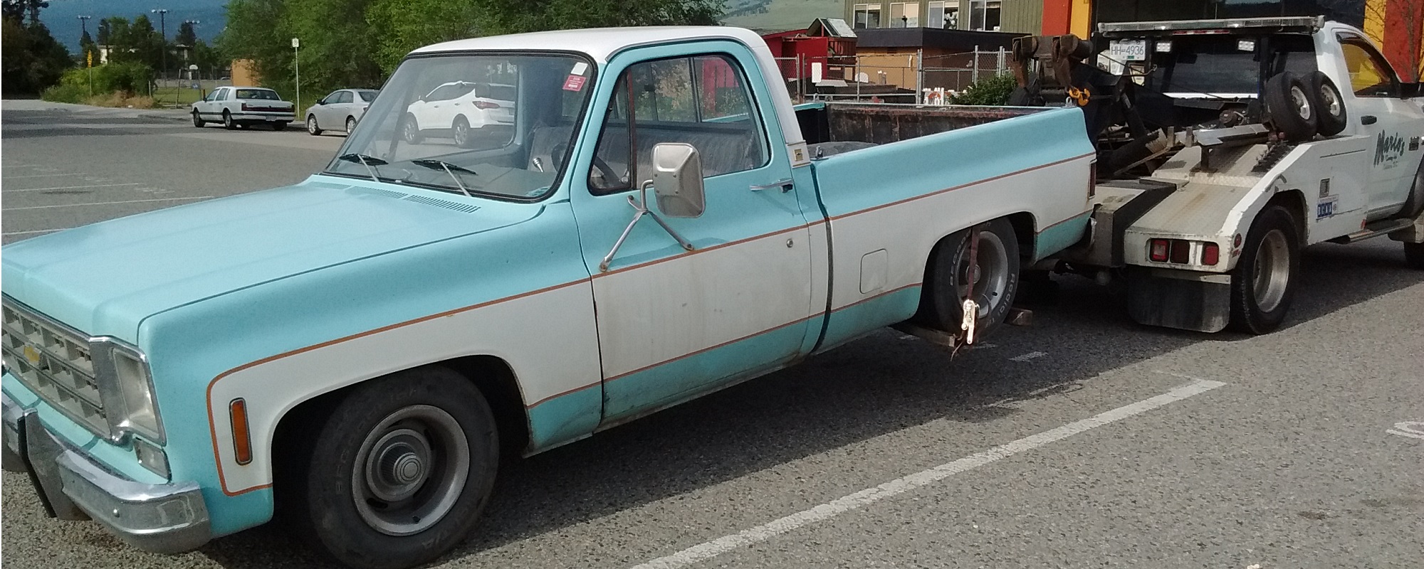
El-Kafrickin-Blammo! When I was an apprentice, I was helping to hook up a freshly installed twin-turbo V8 into a pickup truck. One of the guys took a battery fresh off the charger, and instead of properly connecting the battery clamp, merely twisted the clamp onto the battery post. With the twist of the key to start the engine, there was a tiny spark between the battery post and the battery clamp. This spark ignited the hydrogen around the battery, which ignited in the biggest explosion I had ever experienced up close. The entire top of the battery was gone, as was most of the acid inside. Three guys ran to the sink to rinse the burning acid out of their hair and off their scalp. All of us had ruined clothing. It took me a couple years to become confident around batteries again. |
||||
BATTERY TESTING |
||||
BATTERY HYDROMETERAll 12V batteries have six cells. Each cell produces 2.1V. The six cells are connected in SERIES, so they combine to produce 12.6V. When we re-charge the battery, we put electricity into the hydrosulphuric acid. This electricity actually separates the water (H2O) into Hydrogen and Oxygen. It doesn’t usually return back to the water, but “evaporates.” As the level of acid gets lower due to charging, the battery becomes less effective. In the bad old days, batteries were vented so the hydrogen and oxygen could escape. Over time, the water level had to be topped up with distilled water (NEVER tap water). Today, the battery has special caps that keep everything inside – these (theoretically) do not require any maintenance at all. The electrolyte (acid) in the battery can be tested to see if it’s any good – much like engine coolant can be tested. Electrolyte is drawn from the cell into the Hydrometer Tester to a specific level. A pointer will float and tell you what the Specific Gravity is (the density of the acid – you might remember Specific Gravity from the Periodic Table of Elements). The specific gravity tells us how good the cell is. We’d like all the cells to read the same. This test and the tester is very very similar to the Antifreeze Tester in Cooling Systems. Fully charged is 1.275 Dead is 1.100 Pure water is 1.000
BATTERY LOAD TESTINGToday’s batteries are rated in Cold Cranking Amps (CCA). CCA’s are a way of rating how well a battery can provide current. An average battery today will have a CCA of 500. We can test the output of the battery by sucking current out of it and seeing how well it can continue producing voltage. This is called a Load Test.
We will load the battery to HALF its Cold Cranking Amps (CCA is usually marked on the battery) for no more than 5 seconds (we want to test it, not kill it – and longer loading will burn out our tester. If the voltage drops below 9.6Volts, the battery is dying. Batteries usually last only 5 years before the plates become too sulfated to work properly.
BIGGER IS ALWAYS BETTER I always recommend buying the biggest battery you can fit under the hood of your car. My Lotus 7 Replica is too small fit a full-size battery. I run a lawn-tractor battery in it. The battery has only enough CCA to crank the engine, and if it doesn’t start quickly, the battery is too dead to try again. Never leave the lights on! BATTERY MAINTENANCEEven maintenance free batteries need periodic inspection and cleaning to insure they stay in good working order. Dirty batteries can actually drain themselves through the dirt itself!!.
Use a mixture of baking soda and water and wash the battery and all the metal parts around it. DO NOT allow any of the mixture to get into the battery. Rinse with water. Remove the battery cables from the battery (negative cable ALWAYS first), wire brush the inside of the cable end and the battery post. Reinstall the cables (negative end ALWAYS last). Coat all exposed metal parts( paint or grease can be used) so that the sulfuric acid cannot get on the metal.
|
||||
THE STARTING SYSTEM |
||||
|
The “starting system” does not actually start your car. Doh!
MrWELLWOOD’S LESSON ON STARTERS
A Battery is connected to the key switch The Start Switch is turned to the start position A small amount of current then passes through the Neutral Safety Switch to a Starter Solenoid The Solenoid connects high current directly from the battery to the Starter Motor through thick battery cables. The Starter Motor first engages the FLYWHEEL RING GEAR, and then turns the crankshaft of the engine This causes the piston move to move downward, sucking the Fuel/Air Mixture into the cylinder, where a spark created by the Ignition System will ignite this mixture. If the Compression in the engine is high enough and all this happens at the right time, the engine will start.
HOW THE STARTER MOTOR WORKSThe starter motor is a powerful electric motor which meshes its pinion gear with the ring gear on the flywheel attached to the engine The starter motor then spins the engine over That is ALL the starting system does – turn the engine over – it does NOT make the engine run. If you remember The Square of Electrical Fun from the Ignition System in Level 1, these four are related:
Cover the square you want (for example MOTION), and you need the other three to make it happen. In order to create MOTION from a starter, we need ELECTRICITY going through a COIL OF WIRE. Electricity growing through a coil of wire creates a Magnetic Field. Have this freshly Created Magnetic Field OPPOSE another MAGNETIC FIELD, and we get movement. Basically – have you ever tried to force two magnets against each other against their polarity? Imagine if you could harness that repelling energy. That’s what a Starter does. There are, however, NO MAGNETS in a starter. Even if there were, they wouldn’t be strong enough. Instead, we need to CREATE a Magnetic Field. Actually, we are creating TWO magnetic fields, such that they oppose each other. Just like trying to force two magnets together – the magnetic fields repel each other. One Magnetic Field is created by the FIELD WINDINGS One Magnetic Field is created by the ARMATURE WINDINGS Field Windings:These are the windings inside the starter housing. They surround the Armature, and receive electricity from the battery when the KEY is on START, and the STARTER SOLENOID is engaged. Their sole purpose is to create a magnetic field that opposes the one created at the Armature windings. There is no “magnet” in the starter – a magnetic field is created by running electricity through the Field Windings. Armature Windings:These are the windings inside the rotating armature. The armature contains many separate loops (windings), which are connected to the battery through contact brushes on the commutator. Only the individual windings that contact brushes receive electricity. This creates a magnetic field in the connected coil, which opposes the magnetic field in the Field Windings, and the armature moves. This movement disconnects that one loop and connects the next loop, creating another magnetic field and maintaining movement/momentum of the armature. The sole purpose of the electricity through the Armature Windings is to create a magnetic field. There is no “magnet” in the starter – a magnetic field is created by running electricity through the Armature Windings. Once the two fields oppose each other and begin to rotate, a new set of windings in the armature are connected through the commutator, and these now oppose the field coils. And so on. And so on.
Starters can be tested for how much current they draw while cranking. This is done with the VAT40, which measures the current travelling through the battery cables to the starter. Just crank the engine and measure. I would expect to see around 140 to 250 amps on most cars today.
STARTER SOLENOIDWith 140 to 250 amps going to run the starter, you don’t want that kind of current going to the key switch in the steering column. The heat created could cause a fire. A solenoid is an electrically-controlled mechanical switch (a light switch on the wall is a hand-controlled switch). The Starter solenoid uses the small electrical current from the key switch to connect a large amount of current to the Notice the coils of wire in the drawing on your right. Guess what is created when we MOVE ELECTRICITY through that COIL OF WIRE? Yup. A MAGNETIC FIELD is created. This MAGNETIC FIELD pulls the PLUNGER up, causing the PLUNGER CONTACT DISC to connect the BATTERY TERMINAL (left) to the STARTER TERMINAL (right). Most starters have a solenoid as part of the starter itself (this is typical). In this case, the movement of the solenoid to connect the terminals ALSO pushes the starter drive into the flywheel. The starter drive MUST engage the flywheel teeth BEFORE the starter rotates, or damage will result.
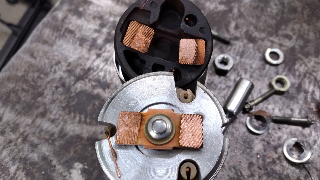
Starter solenoids usually wear out at the contacts inside. Sometimes you can smack it with a hammer to get them to crank once more, and if it works, you’re really on borrowed time. RANDOMLY STRANDED! My ’61 Apache pickup left me stranded every 1 in 100 times. The starter would click, but no cranking. If I got a jump off someone else, their running/charging voltage of 14.6V plus their extra amperage was enough make the connection inside the solenoid, and then it would crank fine 99 more times. I began to suspect the contacts inside the starter solenoid. The solenoid itself is not serviceable, so I cut it open to show you inside – the contacts looked like they were no longer a crisp clean electrical connection, but a damaged, burnt, inconsistent connection:
A new starter was only $98.
|
||||
THE CHARGING SYSTEM |
||||
|
The ALTERNATOR generates and delivers electrical power to the battery and the rest of the vehicles electrical system. The VOLTAGE REGULATOR looks at the state of charge of the battery, and tells the alternator to either produce voltage or not. The FUSIBLE LINK protects the entire car from an electrical problem. It burns out, rather than the entire car burning out. The CHARGE INDICATOR (either a gauge or a light) informs the driver if there is a problem. A car will not drive for very long if it is running only on the battery.
ALTERNATORWe need the alternator to provide ELECTRICITY. Hello Square of Electrical Fun. We meet again….
We want to create ELECTRICITY. To do this, we will MOVE a MAGNETIC FIELD past a COIL OF WIRE. Just like the STARTER, we are going to create this MAGNETIC FIELDS by MOVING ELECTRICITY through a COIL OF WIRE. Wait a minute – are you saying we need to HAVE electricity in order to MAKE electricity? Yes, yes I am. In business: “You need to spend money to make money.” We need to HAVE electricity to MAKE a magnetic field so that we can CREATE electricity with a magnetic field. I know. Just trust me.
MrWELLWOOD’S LESSON ON ALTERNATORS:
Before about 1964 we used a GENERATOR. It used a MOVING (spinning) COIL OF WIRE past a MAGNETIC FIELD to produce ELECTRICITY for us. The strength of output depended on the strength of the magnetic field, and the rotating output coil (being small) didn’t create a lot of electricity. A generator produces DC (Direct Current), the same kind as a battery produces. The Generator was replaced by the ALTERNATOR which produces AC (Alternating current) much more efficiently. In an alternator, the OUTPUT is now stationary (called the STATOR), and the magnetic field rotates (called the ROTOR). The two main parts of the Alternator are the Rotor (it rotates) and the Stator (it’s stationary).
ROTOR:The center rotating part of the alternator which is driven by a belt It receives ELECTRICITY from the voltage regulator and its sole purpose is to become a spinning magnetic field (ELECTRICITY MOVING through a COIL OF WIRE and produces a MAGNETIC FIELD) The strength of this MAGNETIC FIELD, and thus the output of the alternator, is determined by the strength of the current going through it. This is called FIELD CURRENT, and is what we vary to make it charge or not charge. Since the rotor needs to spin, and yet needs electricity, electricity is fed to the FIELD WINDINGS of the ROTOR through brushes contacting slip rings on the shaft. These brushes wear out over time, but are easily replaced. Replacing brushes requires disassembly (it’s very easy to do). IMPORTANT: use a wire to hold the brushes down for reassembly or you will DESTROY the brushes and/or the brush holder. Just like the kids who are not actually reading this will do, but I’m not bitter. All alternators have a hole in the backside just for this purpose. Call me over right ow and convince me you are actually reading this.
STATOR:The stationary outer COIL OF WIRE (windings) of the alternator (this COIL OF WIRE receives the MOVING MAGNETIC FIELD from the ROTOR). ELECTRICITY is then induced in the windings. The Stator is the output of the alternator. This output is Alternating Current (AC), which cannot charge a battery at all (drain/charge/drain/charge – what a waste of time). In order to charge a battery, AC needs to be converted into DC (Direct Current) to be usable.
Rectifier Diodes:One-way doors for electricity that take the bottom half of an AC Sine-wave and flip it to a positive signal. This gives us a ripple voltage which isn’t very smooth for our electrical system. An alternator has THREE sets of overlapping windings in the stator to give us three phase output. This smooths up the output voltage considerably. There are six diodes in an alternator that are used to rectify three-phase AC into DC. A capacitor (a storage container for electricity) is used to absorb the voltage peaks and fill the voltage valleys to provide a dead smooth output voltage.
VOLTAGE REGULATORThe alternator is designed to provide 14.5 Volts. When the battery is low (less than 13.5V) the alternator’s higher voltage will push electrons into the battery to charge it. If the battery is really low, LOTS of current will flow. When the battery is fully charged (14.5V), the battery voltage and the alternator voltage will be the same and the alternator cannot push more electricity into the battery. Current will stop flowing. While the charging system may be able to provide 14.5V of electricity, it may not be able to provide enough (or any) current. When testing alternators, both voltage and amperage outputs are checked. Each alternator has a certain amperage rating. A VAT40 is used to load the charging system down (through a carbon pile) and see what the charging system can produce. Since the battery is a part of the charging system, a dying battery can produce false readings when testing the alternator output. For this reason, the battery should always be serviced and tested FIRST.
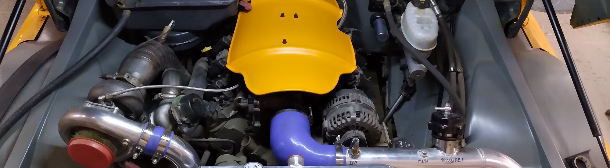
RANDOMLY STRANDED! Years ago I converted my Squarebody to fuel injection. To tune it, I go for a long drive, through a whole bunch of operational ranges, speeds, loads, etc., datalogging what the engine sees and how it responds to the tuning. Problem: The alternator puts out 45 Amps.
Can you see the problem? In finances, spending more than you bring in is called “bankrupt.” When the battery no longer had enough to up with the draw, it just plain quit. Looking back at the datalog, I could see the battery voltage slowly decrease through the whole drive.
A new starter was only $98.
|
||||