
[Drivetrain] [Brakes] [Suspension] [Steering] [Electrical] [Emissions]
QUESTIONS – BrakesBooklet Last Updated: 25/11/21 |
||
We are going to look at:
This is a big unit – so try to work quickly and don’t waste your time. As always – if something seems unclear, it probably is – so ask me for clarification (then I can make it more clear for others) |
||
BRAKES |
||
DESCRIPTION(To all you Physics guys in the class, all brakes do is turn your Kinetic Energy (mass at speed) into Heat. If it cannot turn it into heat, you don’t slow down.) The modern automotive brake system has been refined for over 100 years and has become extremely dependable and efficient. The typical brake system consists of disc brakes in front and either disc or drum brakes in the rear connected by a system of tubes and hoses that link the brake at each wheel to the master cylinder. Other systems that are connected with the brake system include the parking brakes, power brake booster and the anti-lock system.
DRUM BRAKESIn the bad old days, almost all cars and trucks came with drum brakes all around. Drum brakes work by having two curved brake SHOES sitting inside a DRUM. The drum is fixed to the wheel and axle so that it can rotate, and the brake shoes can press against the inside of the rotating drum, providing friction to make it stop. Drum brakes can stop really well, but they cannot withstand a lot of heat from stopping. Brakes work by using friction to convert the motion of the vehicle (Kinetic Energy) into Heat Energy.
Drum brakes have a cool advantage of being self-energizing. When the forward-facing primary shoe (shown on the left) contacts the counter-clockwise-rotating drum, the friction causes the shoe to want to rotate with it. Because the primary shoe is linked to the rearward-facing secondary shoe (shown on the right), its motion helps to apply the secondary shoe HARDER. Watch the bottom part of this image to see it moving more easily:
Notice the primary shoe is smaller (left). It doesn’t do much work – it just gets hits the rotating drum and gets shoved into the secondary shoe. Notice the secondary shoe is larger (right). It does the work here – it is pushed into the drum by hydraulic pressure (via copper on top) AND the “wanting-to-rotate-with-the-drum” primary show (via silver link on bottom).
DISC BRAKESPrior to the 1970’s, only exotic cars had disc brakes. By the 1970’s almost everything had disc brakes on the front. Today many more cars have put disc brakes on the rear as well. Disc brakes use two flat brake PADS that sit against the flat outer surface of a ROTOR. The rotor is fixed to the wheel and axle so that it can rotate, and the pad can press against the sides of the rotating rotor, providing friction to make it stop. Disc brakes require more effort to apply, but can withstand a lot more heat and are even self-cleaning. This process is similar to a bicycle brake where two rubber pads rub against the wheel rim creating friction.
APPLICATIONEarly braking systems were entirely mechanical – they used long rods and levers and linkages to apply braking force from your brake pedal all the way to the wheels. As steering and suspensions improved, the linkages could not do the job very well, and all brake systems switched to hydraulics, which uses flexible high-pressure hoses to connect components.
Let’s follow the basic brake system from start to finish:
|
||
PEDAL ASSEMBLY |
||
|
The brake pedal assembly must be very rigid to withstand any flexing. The pedal usually has a ratio of about 6:1 so 50lbs of force from your foot provides 300lbs (50×6=300) of force to the master cylinder.
|
||
MASTER CYLINDER |
||
|
The Master Cylinder receives the force from the pedal assembly, and converts that force into hydraulic pressure by pressurizing a liquid. For all intents and purposes, a liquid is incompressible and thus exerts that pressure equally in all directions. This makes it easy to transfer through rigid tubes and flexible hoses to get where it needs to go. The greatest advantage of using hydraulics is that it is very easy to increase force. Blaise Pascal discovered that when a liquid in an enclosed container is pressurized, that pressure is distributed equally throughout the system. If the pressure is in pounds per square inch, we can increase force by increasing surface area.
Take the bottle jack example below. Let’s say I apply 10 pounds of FORCE to the pumping piston. This is not a large amount of force. If the piston is one square inch, I will be producing 10 pounds per square inch (psi) of PRESSURE to the fluid in the system. This pressure is distributed equally. Let’s say the Power Piston is 10 square inches in area. Every square inch of that piston will receive 10psi PRESSURE. Since there are 10 square inches, the piston will be able to produce 100 pounds of FORCE. There is a cost – nothing is free. I have to move fluid for this to work. In order to gain force, it ends up costing me travel. I will move the Pumping Piston an inch and the Power Piston only will move 1/10th of an inch because it is 10 times bigger.
Pressure is measured in Pounds Per Square Inch (Pressure [psi]) = (Force [lbs]) ÷ (Area [square inch]) (Force) = (Pressure) x (Area) (Area) = (Force) ÷ (Pressure) If pressure is increased, force goes up. If area is increased, force goes up. If pressure is increased, area must be decreased to keep the force constant
A typical master cylinder has about a 7/8″ piston (0.6 square inches) – this would convert your 300lb force at the pedal to about 500psi (pounds per square inch) of hydraulic pressure. Back in the bad old days the master cylinder had only one piston, and the brake line Tee’d off to all four wheels. The problem with this is if there was even one leak, you would lose ALL your brakes! Because of this, all vehicles since 1966 come with a TANDEM MASTER CYLINDER. This has two pistons (one behind the other) which allows you to have at least half your braking should a leak develop. If primary piston has a leak, the piston will sink until it bottoms against the secondary piston, and build up pressure in the secondary side. If the secondary piston has a leak, the primary piston will push fluid AND the secondary piston down until the secondary piston bottoms, and then build pressure on the primary side. You would end up with a low brake pedal either way, but at least you still have brakes.
Traditionally the Tandem Master Brake System split the brakes front/back. In the advent of Front Wheel Drive (FWD), with the majority of the vehicle’s weight over the front wheels, all FWD cars are split diagonally (that is, one half is the RF and LR wheel, and the other half is the LF and RR wheel). This allows you to still have a big front brake to help stop you – the rear brakes do next to squat on a FWD car.
WHEN INSPECTING: A streak of rust running from the back of the master cylinder down the power brake booster indicates the rear seal in the master is worn out. A brake pedal that slowly sinks to the floor under light pressure indicates the piston seals have worn out. Master cylinders often can be rebuilt.
Master cylinders have become very reliable and rarely malfunction; however, the most common problem that they experience is an internal leak. This will cause the brake pedal to slowly sink to the floor when your foot applies steady pressure. Letting go of the pedal and immediately stepping on it again brings the pedal back to normal height. |
||
BRAKE LINES |
||
|
Brake lines come in two flavours: Solid and Flexible. Solid lines are used virtually everywhere in the vehicle where there is no movement. From the chassis to the wheel assemblies, a special high-pressure flexible line must be used. There must be a flexible line so the suspension can move up and down and the wheels can turn left and right. Brake lines usually use special high-pressure flared fittings. There are a few different flare styles used, and they are not interchangeable.
Rubber brake lines do not last forever – inspect them regularly for cracks, tears, and swelling (indicating an internal failure) – they are easily replaced.
|
||
DRUM BRAKE ASSEMBLY |
||
|
The Drum Brake assembly receives the hydraulic pressure from the Master Cylinder. A typical drum brake wheel cylinder piston might be 1-1/4″ diameter (1.23 square inches), turning the 500psi hydraulic pressure to about 613 lbs of force. The Drum Brake Assembly consists of the following parts:
Backing PlateThe backing plate is what holds everything together It attaches to the axle and forms a solid surface for the wheel cylinder, brake shoes and assorted hardware It rarely causes any problems. Inspect it for rust, and for wear where the brake shoes ride against it.
WHEN DOING A DRUM BRAKE JOB: Put a dollop of Never-Sieze on the raised bumps of the backing plate that the brake shoes ride against.
Wheel CylinderThe wheel cylinder consists of a cylinder that has two pistons, one on each side Each piston has a rubber seal and a shaft that connects the piston with a brake shoe When brake pressure is applied, the pistons are forced out pushing the shoes into contact with the drum Wheel cylinders must be rebuilt or replaced if they show signs of leaking
WHEN DOING A DRUM BRAKE JOB: Peel back the rubber boots just enough to see if the pistons are leaking. If anything more than a drop comes out, they need to be replaced Smack one shoe, and see if the shoe moves the piston through the wheel cylinder to move the other shoe. This indicates that the pistons are not stuck or seized. If the piston is not free-moving, the wheel cylinder is seized and must be replaced.
Brake ShoesBrake shoes consist of a steel shoe with the friction material or lining riveted or bonded to it. The linings eventually wear out and must be replaced. If the linings are allowed to wear through to the bare metal shoe, they will cause severe damage to the brake drum.
WHEN INSPECTING BRAKES: When the friction material is as thick as the backing plate, the brakes are worn out. WHEN DOING A DRUM BRAKE JOB: New brake shoes must be adjusted properly when assembling them. This is as simple as test-fitting the drum on, and checking for some drag on the brakes – you should feel some resistance as you try to rotate the drum. If there is no resistance, you need to turn the self-adjuster a bit until the brakes slightly drag. What do you think the pedal would feel like if the self-adjusters were not self-adjusting, and the friction material is significantly worn?
Brake DrumBrake drums are made of iron and have a machined surface on the inside where the shoes make contact Just as with disc rotors, brake drums will show signs of wear as the brake linings seat themselves against the machined surface of the drum When new shoes are installed, the brake drum should be machined smooth Brake drums have a maximum diameter specification that is stamped on the outside of the drum. When a drum is machined, it must never exceed that measurement. If the surface cannot be machined within that limit, the drum must be replaced.
Return SpringsReturn springs pull the brake shoes back to their rest position after the pressure is released from the wheel cylinder. If the springs are weak and do not return the shoes all the way, it will cause premature lining wear because the linings will remain in contact with the drum. A good technician will examine the springs during a brake job and recommend their replacement if they show signs of fatigue. On certain vehicles, the technician may recommend replacing them even if they look good as inexpensive insurance.
Self Adjusting SystemThe parts of a self adjusting system should be clean and move freely to insure that the brakes maintain their adjustment over the life of the linings. If the self adjusters stop working, you will notice that you will have to step down further and further on the brake pedal before you feel the brakes begin to engage. Since the emergency brake applies the rear brake drums, you will also notice the e-brake only grips at the top, or not at all – Adjust the brakes FIRST, this usually fixes it 95% of the time. When a technician performs a brake job, aside from checking the return springs, he will also clean and lubricate the self adjusting parts.
WHEN DOING A DRUM BRAKE JOB: Always disassemble the self-adjuster mechanism, wire-wheel the rust off, and liberally coat with Never-Sieze. This is the most problematic part of drum brakes.
Drum Brakes are “Self-Energizing.” As the brakes are applied to a rotating drum, the primary shoe (the forward shoe) contacts the friction surface of the drum, it grips the drum and uses the rotation of the drum to apply the secondary shoe (the rear shoe) even harder. Because of the Self-Energizing feature, drum brakes work really well. …Up until they overheat and fade.
WHEN DOING A DRUM BRAKE JOB: The Primary Shoe is smaller and goes on the front. The Secondary Shoe is larger, and goes on the rear. Installing them backwards makes it stop really well in reverse, but not forward.
|
||
DISC BRAKE ASSEMBLY |
||
|
The disc brake is the best brake we have found so far. Disc brakes are used to stop everything from cars to locomotives and jumbo jets. Disc brakes wear longer, are less affected by water, are self adjusting, self cleaning, less prone to grabbing or pulling and stop better than any other system around. While drum brakes require springs to pull the shoes back off the drum, disc brake calipers have an O-Ring that has a square cross-section – the o-ring seals against the piston to keep fluid inside, but also flexes as the piston moves to apply the brakes. Then pressure is released, the square shape of the seal flexes back, pulling the piston and pad off just a wee bit off the rotor. While drum brakes need to be periodically adjusted, disc brake calipers merely push the piston out further as the pads wear. The square O-ring pulls the piston the same wee amount, maintaining correct clearance. Super simple.
They consist of the following components:
Caliper & SupportThere are two main types of calipers: Single piston floating calipers and four piston fixed calipers. There are other configurations but these are the most popular. Calipers must be rebuilt or replaced if they show signs of leaking brake fluid or of the pistons sticking inside.
Single Piston Floating CalipersThese are the most popular and also least costly to manufacture and service. This type of caliper “floats” or moves in a track in its support so that it can center itself over the rotor. As you apply brake pressure, the hydraulic fluid pushes in two directions. It forces the piston against the inner pad which in turn pushes against the rotor. It also pushes the caliper away from the piston, pressing the opposite side of the caliper against the other side of the rotor. The caliper is locked into its track by sliders that must be lubricated with high temperature “never seize.” If they stick and prevent the caliper from sliding, your braking will be cut in half because only the piston-side pad will work (A clue: the piston-side pad will wear out much faster).
WHEN DOING A DISC BRAKE JOB: It’s a good idea to see how easily the pistons return inside the caliper. If they cannot be easily pushed with a small c-clamp, there is probably crud and/or corrosion inside that will make the piston stick (you should have changed your brake fluid more frequently!). Sticking pistons usually stick “on” and stay on once you hit the brakes. Also, make sure the caliper SLIDERS move freely. Often they need to be disassembled, wire-wheeled and coated with Never-Sieze. A stuck caliper slider will cause only ONE brake pad (the one against the PISTON) to wear on a floating caliper system (if the caliper doesn’t “float,” the outside (non-piston) pad will never be applied).
WHEN DOING A REAR DISC BRAKE JOB: Many rear disc brakes ALSO apply the parking brake. Parking brakes are applied MANUALLY, usually by a cable. Part of how this works makes the piston sort of “unscrew” from the caliper as the brakes wear. You CANNOT push the piston back in – it must be threaded back in. To do this, you may need the Disc Brake Cube. One of the pairs of bumps on there will work for you. The square hole is 3/8″, and will fit your ratchet/extension.
Four Piston Fixed CalipersThese are mounted rigidly to the support and are not allowed to move. Instead, there are two pistons on each side that press the pads against the rotor. Four piston calipers have a better feel and are more efficient, but are more expensive to produce and cost more to service. This type of caliper is usually found on heavy-duty, luxury and high performance cars.
A typical four-piston fixed caliper
Brake PadsThere are two brake pads on each caliper. They are constructed of a metal “shoe” with the lining riveted or bonded to it. The pads are mounted in the caliper, one on each side of the rotor.
HEALTH RISK: Brake friction materials used to be made primarily of Asbestos because of it handles heat REALLY well and is QUIET. However, due to health risks (contracting Asbestosis), Asbestos has been outlawed, so new materials are now being used. Brake pads wear out with use and must be replaced periodically. There are many types and qualities of pads available. The differences have to do with brake life (how long the new pads will last) and noise (how quiet they are when you step on the brake). Harder linings (like Metallic, or Ceramic) tend to last longer and stop better under heavy use but they may produce an irritating squeal when they are applied. They may also eat the rotors a lot faster. Brake pads should be checked for wear periodically. If the lining wears down to the metal brake shoe, then you will have “Metal-to-Metal” causing severe damage and loss of braking efficiency. I have a look at my brakes every time I swap winter/summer tires.
Some brake pads come with a “brake squealer” that will emit a squealing noise when the pads are worn to a point where they should be changed. It sounds terrible. This noise will usually be heard when your foot is off the brake and disappear when you step on the brake. If you hear this noise, have your brakes checked as soon as possible. Some cars have an electrical sensor IN the brake pads, which put a light on the dash to warn you – again: deal with this as soon as possible.
WHEN INSPECTING: If the friction material is as thick as the brake pad backing plate, they are worn out. I once had a set of competition brake pads made for a car I raced. They made the friction material a little too thick, and I could not fit them inside the calipers. It felt really wrong to clamp the brand new pads onto the milling machine and cut off a few thousand miles of braking material off….
RotorThe disc rotor is made of iron with highly machined surfaces where the brake pads contact it. Just as the brake pads wear out over time, the rotor also undergoes some wear, usually in the form of ridges and groves where the brake pad rubs against it. This wear pattern exactly matches the wear pattern of the pads as they seat themselves to the rotor.
When the pads are replaced, the rotor must be machined smooth to allow the new pads to have an even contact surface to work with. Only a small amount of material can be machined off of a rotor before it becomes unusable and must be replaced. A minimum thickness measurement is stamped on every rotor and the technician doing the brake job will measure the rotor before and after machining it to make sure it doesn’t go below the legal minimum. If a rotor is cut below the minimum, it will not be able to handle the high heat that brakes normally generate. This will cause the brakes to “fade,” greatly reducing their effectiveness to a point where you may not be able to stop! Even still, a rotor may “warp” from the high heat of braking, making the brakes pulsate or “shake” when you step on them. A warped rotor can usually be machined smooth again (called “turning a rotor”), but if it’s too thin it must be replaced.
Note to myself for our new brake lathe: https://www.youtube.com/watch?v=OCrm61xlQO8
|
||
BRAKE FLUID |
||
|
Brake fluid is a special oil that has specific properties:
It must withstand cold temperatures without thickening It must withstand high temperatures without boiling (If the brake fluid should boil, you get air bubbles in the fluid = spongy pedal and the car will be hard to stop).
Brake fluid must meet standards that are set by the Department of Transportation (DOT). The current standard is DOT-3 which has a boiling point of 460º F. But check your owners manual to see what your vehicle manufacturer recommends.
The brake fluid reservoir is on top of the master cylinder. Most cars today have a transparent reservoir so that you can see the level without opening the cover. As brake pads wear, the brake caliper pistons have to travel further – this causes the brake fluid level to go down. If the level drops noticeably over a short period of time or goes down to about two thirds full, have your brakes checked as soon as possible.
NEVER leave brake fluid exposed to air. Keep the reservoir covered except for the amount of time you need to fill it. Exposure to air will cause the fluid to absorb moisture out of the air which will make it boil more easily. BOILED BRAKE FLEID = SPONGEY PEDAL NEVER use fluid with air bubbles in it. Air can compress, which causes a spongey pedal and severely reduced braking efficiency. If air is suspected, then the system must be bled to remove the air. There are “bleeder screws” at each wheel cylinder and caliper for this purpose. Brake fluid doesn’t last forever. It should be REPLACED every TWO YEARS. Few people ever do. NEVER PUT ANYTHING BUT APPROVED BRAKE FLUID IN YOUR BRAKES. ANYTHING ELSE CAN CAUSE SUDDEN BRAKE FAILURE! Any other type of oil or other fluid will react with the brake fluid and very quickly destroy the rubber seals in the brake system. A student a number of years ago accidentally put engine oil in the brake system instead of brake fluid. The rubber seals in the brake system were not compatible and began to swell like one of those toy dinosaurs in an egg that you put in water for a week. When we took the master cylinder cover off, the rubber seal in the cap popped out twice its normal size! The ENTIRE brake system had to be rebuilt.
|
||
OTHER COMPONENTS |
||
Metering ValveThis valve is normally found on Disc/Drum cars. Disc brake caliper pistons are retracted by a square o-ring and consequently, the brake pads ride so close to the rotor that they operate almost instantly. Drum brake shoes, however, are retracted by springs. When the brakes are applied, braking force must first overcome the rear brake spring pressure before the shoes even start to move. In the mean time, the front brakes are already applying. The Metering Valve “slows down” the application of brake pressure to the front calipers until sufficient pressure has been built up in the rear.
Brake Warning Light SwitchThis is done usually one of two ways:
Pressure Differential ValveThis valve is usually mounted just below the master cylinder and is responsible for turning the brake warning light on when it detects a malfunction. It measures the pressure from the two sections of the master cylinder (front and rear, for example) and compares them. If there is a difference in pressure (say, half the car has been sheared off), the piston moves off-center by the higher pressure, triggers a warning light, and may even seal off the leaking half.
Low Fluid IndicatorThis is merely a float inside the master cylinder controlling a switch. When the float drops below a certain level, a brake warning light is turned on, indicating a fault with the brake system.
Proportioning ValveThis valve is mounted between the master cylinder and the rear wheels. They are designed to adjust the pressure between the front and rear brakes depending on how hard you are stopping. The harder you stop, the more of the vehicle’s weight is transferred to the front wheels, and off of the back wheels. This could cause the back wheels to lock, causing a dangerous spin. These valves are designed to direct less pressure to the rear the harder you stop. This minimizes the chance of premature lockup at the rear wheels. You do the same thing when you brake your bicycle – you balance front and rear braking pressure with the brake levers depending on what you are doing and fast you are stopping.
Many pickups have a Load-Sensing Proportioning Valve – it has a simple valve that senses when the box is loaded (the rear of the truck is lower than normal), and allows more braking force to the rear. I lowered a pickup once that had one of these valves – with a 5″ drop, the rear brakes thought I was carrying a Winnebago and gave me enough rear braking to lock the rear wheels in light braking (death – instant spin braking in a turn). I had to relocate the valve lever 5″ lower to make it happy again.
Combination ValveThe Combination valve is simply a Metering Valve, Proportioning Valve and a Pressure Differential Valve combined into one unit.
|
||
PARKING BRAKES |
||
|
The parking brake (or emergency brake) is a mechanical (separate from the hydraulic system) method of applying the brakes. It usually only applies to the rear brakes, and is used to hold the vehicle parked, as well as attempt to stop the vehicle should the entire hydraulic system have failed. Steel cables are connected to either a hand lever or a foot pedal and physically apply the rear brakes. On drum brakes, the cable pulls on a lever mounted in the rear brake and is directly connected to the brake shoes. Disc brakes on the rear wheels add additional complication for parking brake systems. There are two ways to do this: The first type uses the existing rear wheel caliper and add a lever attached to a mechanical corkscrew device inside the caliper piston. When the parking brake cable pulls on the lever, this corkscrew device pushes the piston against the pads, thereby bypassing the hydraulic system to stop the vehicle. This type is common with single piston floating calipers. The other system uses a complete mechanical drum brake unit mounted inside the rear rotor. The brake shoes on this system are connected to a lever that is pulled by the parking brake cable to activate the brakes. The brake “drum” is actually the inside part of the rear brake rotor. On cars with automatic transmissions, most people rarely use the parking brake – this is a bad idea. If the e-brake is not used, the cables and levers that operate it can seize, preventing it from working or once applied, preventing it from being released. Many drum brake systems are automatically adjusted by using the e-brake. If the e-brake isn’t used, the brakes don’t get adjusted as they wear.
|
||
POWER BRAKES |
||
|
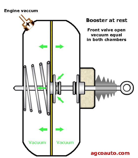
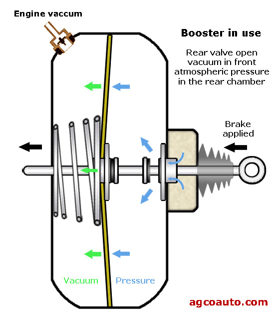
The brake power booster uses atmospheric pressure and engine vacuum to provide additional braking force. In order for the power assist to work, the engine must be running. A large round drum is mounted on the firewall directly behind the master cylinder. A link from the pedal assembly goes into the power booster, and a link from the power booster goes to the master cylinder. Inside the power booster, there is a rubber-sealed diaphragm that separates the atmospheric side (the brake pedal side) from the engine vacuum side. When the brake pedal is pressed, a small valve is opened, allowing atmospheric pressure to enter, an push against the diaphragm (trying to collapse the engine vacuum). This pressure, against the surface area of the booster diaphragm, adds considerable force. The caveat in the system is the engine must be running. If the engine quits, you lose the vacuum to make the system work. You will still have brakes and can still stop the car, but it will take a lot more force to do so.
As a safety precaution, there is a check valve in the vacuum line which allows the booster to store some vacuum. This is there to give you about three brake applications even if the engine quits running. You will know when the valve is leaking when your foot is on the brakes and you shut the engine off – the loss of vacuum makes the brake pedal instantly rise.
|
||
ANTI-LOCK BRAKE SYSTEM |
||
|
Skidding the tires does not stop fast. Skidding tires cannot steer around an obstacle. Having the tires just on the verge of skidding stops fast. A good driver can modulate the bake application (by pumping the brake pedal) to be just on the verge on locking and skidding. Most of us are not good drivers. Anti-Lock Brakes (ABS) can help that. ABS is not intended to make your car stop sooner (gasp! Say it isn’t so!). It is intended to allow you to steer around obstacles and avoid the collision. A skidding tire does not stop, but a skidding tire also does not steer. Anti-lock brake systems solve this lockup problem by looking at wheel speeds and rapidly pumping the brakes of whatever wheel is locking up.
Only the wheel that is locked will be pumped, while full braking pressure stays available to the other wheels. This allows you to stop in the shortest amount of time while maintaining full steering control even if one or more wheels are on shear ice coated with soapy water and a layer of grease. This “pumping” of the brakes occurs at ten or more times a second, far faster then a human can pump the brakes manually. If you step on the brakes hard enough to engage the anti-lock system, you may feel a strong vibration in the brake pedal. This is a normal condition and indicates that the system is working, however, it can be disconcerting to some people who don’t expect it. If your vehicle has anti-lock brakes, read your owner’s manual to find out more about it. The system consists of an electronic control unit, a hydraulic actuator, and wheel speed sensors at each wheel. If the control unit detects a malfunction in the system, it will light an ABS warning light to let you know that there is a problem. If there is a problem, and the anti-lock system will not function but, the brakes will otherwise function normally.
One time, after doing reverse donuts in my wife’s car, the ABS light came on, and the ABS system stopped working. I checked the computer trouble codes, and it said the right front ABS sensor was dead. These sensors were $250, and I didn’t want to pay that – I wanted to make SURE that sensor was, in fact, dead. I hooked up my trusty Oscilloscope, and discovered that the sensor was in fact sending a Sine Wave signal. Somehow the signal was not getting to the computer.
|
||