
POWER ADDERS!
[Automatics] [Differentials] [Engine Performance] [Boost & Nitrous] [Lifting & Lowering] [Balancing & Blueprinting]
QUESTIONS – Boost & N2O |
|
| [ NITROUS ] [ SUPERCHARGERS ] [ TURBOCHARGERS ] | |
NITROUS OXIDE |
|
History |
|
|
No thanks to “Fast And Furious,” Nitrous Oxide is NOT called “NOS” (Naahs). “NOS” is a manufacturer of Nitrous Oxide Systems, called (oddly enough) “Nitrous Oxide Systems.” “Nitrous Oxide” is usually just abbreviated to “Nitrous” (not “NAAHS”, you poser). Nitrous is nothing new. It was first experimented with by chemist Joseph Priestly in 1775 who apparently enjoyed inhaling it with his friends. Nitrous’ nickname is “Laughing Gas.” It became used in dentistry as an anesthetic around 1840 as it is fast acting and takes the “edge” off of pain (Ambulance ride: I found it made my voice deeper). It was originally used as an engine performance enhancement in WWII Germany to assist the Luftwaffe fly at very high altitudes. Nitrous became a significant additive in drag racing through the 1960’s to now, and is a popular easy way to add power from small to catastrophic amounts. Racing grade Nitrous has trace amounts of Sulfur added to discourage more “recreational” pursuits. Other names: “Spray,” “Squeeze,” “Gas,” “Laughing Gas,” “Juice,” etc..
|
|
Chemistry |
|
|
Nitrous Oxide is N2O = two parts Nitrogen, one part Oxygen. And no thanks to “Fast and Furious,” Nitrous Oxide does not burn. Our atmosphere is made up of (approximately) 78% Nitrogen and 21% Oxygen. If Nitrous were flammable, don’t you think if you struck a match, the entire globe would be obliterated? It is their chemical bonding that supplies an extra molecule of oxygen into the mixture, released during the heat of compression. More oxygen equals a more rapid combustion. If you have ever used a cutting torch, you know that the basic flame heats the metal, but pressing the cutting lever on the handle adds pure oxygen to the flame, which instantly blows a molten hole through solid steel. Nitrous can (and will) do the same thing to your engine – it intensifies the combustion. Nitrous is 57% more oxygen than earth’s atmosphere – you have to give it more fuel to burn.
|
|
Components |
|
CylinderNitrous Oxide is stored in a pressurized cylinder at 600-800 psi as a liquid. Some people have used old fire extinguishers as a Nitrous tank, but most filling stations today will not fill anything but the proper cylinder. Pressurized cylinders are usually tested every ten years for safety and proper pressure relief valve operation (valves are usually replaced). For the best and most consistent effect, the tank pressure should be kept constant, preferably 800psi. Unfortunately, as the Nitrous is used, a couple things work against us: If you pressurize a gas or a liquid, you raise its boiling point If you raise the boiling point enough, it will change state (gas becomes liquid, liquid becomes solid) If you release the pressure, a liquid (for instance) will instantly boil (Propane becomes a liquid when it is pressurized in the cylinder, but comes out as a gas when you open the valve, because it is boiling inside the tank when un-pressurized) A liquid rapidly changing state in this manner will draw heat out of the surrounding air (that’s why you see frost building around heavily-used propane tanks, or why spray bombs get cold when you use them a lot) Frost building around a tank cools the tank and its contents Cooled contents of a tank will decrease cylinder pressure Reduced cylinder pressure = reduced Nitrous delivered = less power output Some people try to get around the loss of pressure by keeping the tank at a constant temperature with (essentially) an electric blanket. You need to be careful with this. The tank should vent any excess pressure, and it should be vented outside the car. Not inside.
Most motor vehicle acts require certain standards to be met in the transport of pressurized cylinders, including storage, securement, ventilation and exterior signage. Nitrous kits do not generally meet these legal requirements. Supply LinesNitrous is usually delivered to the motor via a stainless-steel braided high pressure hose. These are often referred to as AN-lines. AN stands for Army/Navy, and you see them in all race cars, airplanes, and space equipment. The hose must be properly secured to the vehicle, and must not chafe against any sharp edges. Hoses that pass through bulkheads of the passenger compartment must be sealed to prevent fumes from entering the passenger area. Additional fuel required for the Nitrous can be tapped into the existing fuel line, but is best delivered from its own separate fuel pump, filter, and lines.
SolenoidsThe Solenoids are electrically-controlled mechanical valves that open and close to control the flow of Nitrous and Fuel (each with their own solenoid) to enter the engine.
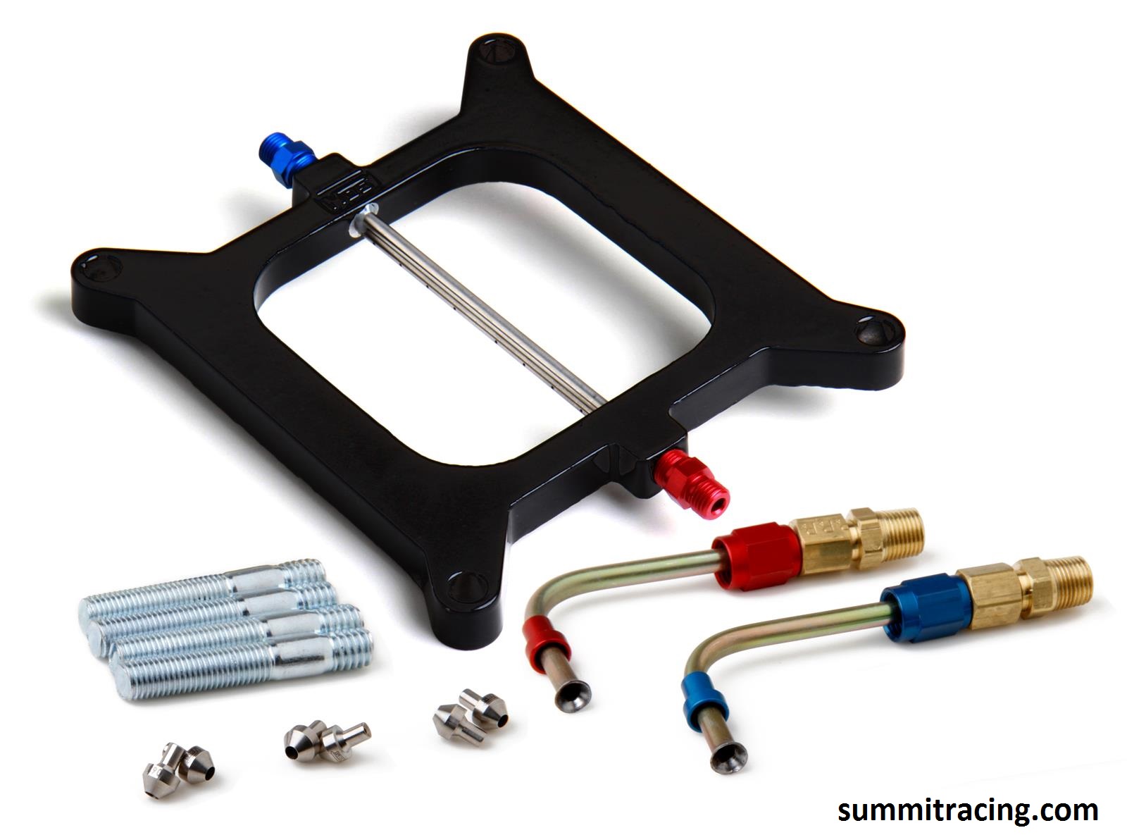
Nozzles & JetsNozzles are required to distribute the Nitrous and fuel into the air stream. Traditionally they were merely a tube with holes in it that was placed in the air stream; one for fuel, one for nitrous. With a critical need to ensure the Nitrous is well mixed with the fuel, “Fogger” nozzles became popular.
Different Jet sizes are available to flow more or less nitrous and/or fuel. This is where it is not a good idea to be greedy. These jets are essentially the same as you would find in an old carburetor. Most Nitrous kits will come with some reasonable jet sizes, and you can quickly and easily change them to delightfully unreasonable size.
SwitchesYou need two switches. One to “Arm” the system (so your grandma doesn’t accidentally hit the Nitrous on the way to her knitting circle), and one to apply the Nitrous. Many people like to hide the switches for Nitrous so nobody knows they have it. The switches for nitrous should be “Normally Open Momentary Contact” switches. That means they don’t connect until you hit them, and they shut off when you let go. This way when you release the button, the system shuts off. Nitrous will produce the most power when the engine is at wide open throttle. Because of this, I am a big fan of running the Nitrous switch off the actual throttle itself, right at the throttlebody or carburetor, so it will only turn on when your foot is to the floor. One less thing to think about.
|
|
Requirements |
|
|
There are a number of things your vehicle MUST have to be most effective running Nitrous: Engine: Make sure the engine is in good shape, and run good oil. Leaking intake valves can allow Nitrous in the intake system to be ignited (Kaboom!). Quality engine oil is needed due to the increased load on the bearings from combustion. Ring gaps should be increased with large amounts of spray so the rings don’t expand too much, butt together, and break the ring lands of the piston. Fuel: The fuel system must be 100%, and you need to provide MORE fuel. You must be able to supply constant fuel, with no air bubbles or possibility of going lean. Lean, even for an instant, is instant no-warning death for your engine. Some people install “purge” systems to make sure there are no bubbles (and to intimidate others). Running Premium, high-octane fuel is required. Ignition: The ignition system must be 100%. You must be able to supply high quality spark at exactly the right time. Pre-ignition or detonation, even just a wee bit, will instantly destroy your engine. Timing: Ignition timing should be bumped back a few degrees. There is going to be a lot more cylinder pressure, you’re not going to want it exploding by itself or at the wrong time. Spark Plugs: Should be one or two steps colder than the manufacturer’s recommendations. This reduces the chance the spark plug becoming a “hot spot,” pre-igniting the air/fuel, and the resultant engine damaging detonation. This also means the plugs are more likely to foul in everyday driving. Plug gaps should be about 10% smaller to make it easier to spark; less likely to misfire. A misfire in the cylinder allows unburned Nitrous into the exhaust. If it ignites in the exhaust, you will experience the backfire to end all backfires: It can blow the pipes clean off the car. Cooling: Running a cooler thermostat (say, 160° instead of 190°) also reduces the chance of detonation. Internal Mods: If you’re smart, you’d build you engine with heavy duty forged pistons, forged rods, and a forged crankshaft, and open the piston ring gaps wider to handle the increased combustion temperatures.
|
|
SUPERCHARGERS |
|
History |
|
There is a saying: “There’s no replacement for displacement.”Except there actually is. It’s called BOOST.While the easiest way to make more power it to get a bigger engine, a close second is to just stuff MORE air into our existing engine. If my 2L engine can be fed 4L of air, it should make the same power as a 4L engine! All we need is a method of forcing the air into the engine. Francis Roots invented a twin-rotor air pump in 1860. In 1900, Gottlieb Daimler (founding father of Daimler-Benz) used one on one of his engines. Superchargers became more common on the racecars of the 1920’s. They were, however, expensive and not very reliable. The 1920 “Blower” Bentley may have given the supercharger the name “Blower,” while some believe its name came from what it did to the rest of your motor. Supercharging was used through WWII on aircraft to assist in flying at high-altitude. It had continued use in automobiles through the 1950’s to the 1980’s, but usually as an aftermarket add-on. By the mid 1980’s manufacturers began playing with Forced Induction again. Notably Chrysler with turbochargers, but Toyota and Ford (and others) offered supercharged models from the factory. Today, GM, BMW, Audi, Ford and many others have supercharged vehicles available.
|
|
Types |
|
|
There are three types of superchargers in common use today, each with their own advantages and disadvantages: Roots:The original. Two rotors with two or more lobes rotate in a housing. The rotors are driven directly by the crankshaft by either belts or gears. Air is drawn in along the outer spaces of the lobes. Pressure is built inside the manifold itself (not the blower), as more being stuffed in than the engine actually displaces. This is called a “Positive Displacement” supercharger. These superchargers have a relatively narrow range of efficiency, and it’s not very efficient at that (30-40%). If they spin too slow, they do not build boost (inefficient). If they spin too fast they create too much heat (inefficient). The rotors do not always seal well against the housing (inefficient), and they are difficult to lubricate (inefficient). The most familiar Roots-Type Supercharger is the GM 6-71, often called the “Jimmy.” It is originally used on two stroke diesel engines just to get air into the engine. It’s numerical designation “6-71” means that it can feed a 6 cylinder engine, whose cylinders are 71 cubic inches in size. That means in one revolution, the blower will displace 426 cubic inches of air (6 x 71). Spin that blower twice as fast as the crankshaft, and you could stuff 852 cubic inches of air into a 426 Hemi. Since atmospheric pressure is 14.7psi at sea level, this setup would provide 14.7psi of boost (in a perfect world), and the engine would produce twice the horsepower as it would have naturally aspirated (in a perfect world). Since the air stuffed into the engine is going to be a multiplier of the engine displacement, a roots type supercharger will produce boost very linearly (it really depends on what rpm range its efficiency is at). eg: 2000rpm = 6psi, 4000rpm = 6psi, 6000rpm = 6psi (though little to no boost at idle because they aren’t super well sealed inside). Roots type blowers tend to have a noisy “gear whine” from the rotor gears (though some say that’s actually the belt making the noise??) as well as the spinning rotors.
Centrifugal:Kind of like half a turbocharger (looks like a hair dryer), driven by a belt. Paxton is one of the original manufacturers of this supercharger, having installed them as early as 1937 on Flathead Ford V8’s. Through the 50’s and 60’s, the Paxton Supercharger found its way onto Studebakers, Packards, and even a factory option on the 1957 Ford Thunderbird. Carroll Shelby (of Shelby Cobra fame) had them installed on a number of GT-350’s, and they were also a dealer option on Mustangs from 1965 to 1972. While there are other manufacturers, Paxton is considered the “original.” Essentially a spinning impeller driven by the crankshaft, mounted inside a scroll housing. It is far more efficient than the roots type supercharger (close to 75%), and produces boost exponentially. Eg: 2000rpm = 2psi, 4000rpm = 4psi, 6000rpm = 16psi. Centrifugal superchargers build boost internally, by the high speed air from the impeller passing through the housing. The air entering the cylinders is already pressurized.
SCREW:Instead of pumping air around the outside of the rotors as in the Roots, the Screw draws air in one end and forces it through the supercharger, compressing it as it goes. While it does act as a positive displacement supercharger, it actually builds pressure inside the supercharger itself. It also is generally quieter than a Roots Blower in operation (it does have a very unique whine), and best of all, it is very efficient!
|
|
Selection |
|
|
The document linked below works you through the selection of a supercharger for a 302 V8 engine. It is fairly detailed in the math involved, but does not use very complex math. It is basically a plug in the numbers formula. Read (but DO NOT DO) this page to get an idea on what is involved. You will calculate for a turbo later: THEORY – Selecting a Supercharger |
|
AS WITH NITROUS…. |
|
|
You still need to REDUCE Spark Timing with boost (generally 1° per 1psi of boost) You still need to provide ENOUGH fuel If you don’t provide enough fuel, the engine will eat the pistons as fuel instead You still need to provide STRONG spark You still should INCREASE the piston ring gap. Your stock engine management system will not cut it. |
|
TURBOCHARGERS |
|
History |
|
NOTE: LATER IN THE WORKSHEET, YOU ARE GOING TO NEED THIS WEB PAGE (Selecting a Turbocharger)A turbocharger is a turbine-style of air pump that is driven by the exiting exhaust of the engine, rather than directly by the crankshaft as is a supercharger. As such, a properly sized turbocharger can reach maximum boost very early on in the rpm range, whereas a supercharger will feel just like a naturally-aspirated engine, only larger. Unfortunately, because the turbo is driven by the exiting exhaust, there is a delay (called “lag”) in the building of boost where we stomp on the gas: throttle is opened, air and fuel is consumed, compressed, burned, and then exited before the turbo even begins to spin faster. Engine under load = maximum exhaust = full boost as set by waste gate Engine cruising = minimum exhaust = no boost; turbo “coasts” doing nothing Turbochargers are also usually significantly more efficient than a typical supercharger (the screw type being a close second to the turbocharger). The Turbocharger was a development of Alfred Buchi who patented the design for engine use in 1905 and were originally used on Diesel engines. They were first used on a gas engine in a V12 Liberty aircraft around 1918 to assist in high-altitude flight. While widely popular in motor racing, the turbocharger wasn’t offered in a production car until the Oldsmobile Cutlass Jetfire and the Chevrolet Corvair Monza Spyder, both in 1962. GM dropped the turbocharger after a few short years. Europe began using the turbocharger in the 1970’s, while North America didn’t really start playing with it until the 1980’s in an effort to produce power while maintaining reasonable fuel economy and emissions. Chrysler, notably, began turbocharging virtually everything they sold from 1984 on, producing phenomenal amounts of power. In 1986, Hot Rod Magazine pitted the (then new) turbocharged Dodge Omni GLH-S against a 1966 Shelby Mustang GT-350. The Mustang lost. In every test. Turbos have very much become popular again since the early 2000’s, in both the aftermarket world as well as the almost all manufacturers still trying to meet power/fuel-economy/emission goals.
One of the down sides of turbocharging, is “lag.” Because the turbo runs off the exhaust, you don’t make boost until you have enough exhaust to spin it. You step on the gas to pass a car, more air and fuel go in, gets burned, goes out the exhaust, spins the turbine which spins the compressor which forced in MORE air and THEN off you go. There are ways to reduce lag, but it’s usually there to a certain extent. MUCH worse the larger the turbo you go. Small turbos spool (get up to speed) quickly, but are limited for top-end power. Large turbos take a while to spool up, but when they do – hang on! The VSRacing 7875 on the 6.0L in my ’61 Chevy Apache Pickup spools like a lightswitch – it just feels like a LARGE engine. In the time it takes for the transmission to downshift, I’m on boost – I’ve had to learn how to “lean into the throttle” instead of “stabbing it” (instant tire smoke). Absolute giggles on the street.
|
|
Components |
|
|
There are three fundamental parts to a turbocharger: Compressor The inlet side of the turbo. Sized to provide the boost and air flow required for engine performance. Center Housing: Lubricated by engine oil, it supports the turbine shaft. Ball-bearing centres help the turbo to “spool up” (build boost) faster. More expensive centers may have water-cooling as well. (INTERESTING VIDEO: THE TRUTH About Ball Bearing vs Journal Bearing Turbochargers!) Turbine: The exhaust side of the turbo. Driven by exiting exhaust gasses, the hotter and greater the exhaust, the faster the turbine will spin. The turbine is directly connected to the compressor, which then forces more air into the engine.
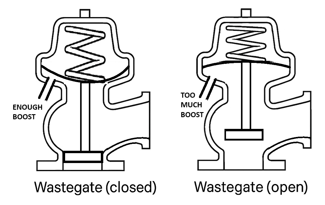
Other components that make the turbocharger system effective:Waste GateA bypass valve in or near the exhaust turbine to reduce boost by bypassing exhaust gasses before it gets to the turbine itself. They have a specifically sized spring that holds a “bypass” in the exhaust before the turbo closed. Boost pressure (and to a certain extent exhaust backpressure) works against the spring to open the bypass allowing exhaust to bypass the turbo, thus limiting boost. Integral wastegates have a finite amount of flow (they only flow so much). Once you start running higher boost than the wastegate can flow, you get “boost creep” (boost continues to climb, even if you don’t want it to). Wastegates can come in different sizes. Too big is better than too small. PLACEMENT is KEY – you want the exhaust to flow to WANT to exit through the wastegate. If the exhaust flow prioritizes the Turbo, you will have a harder time controlling boost, and may get “boost creep” – that is, the system can’t control the boost, and boost keeps climbing and climbing.
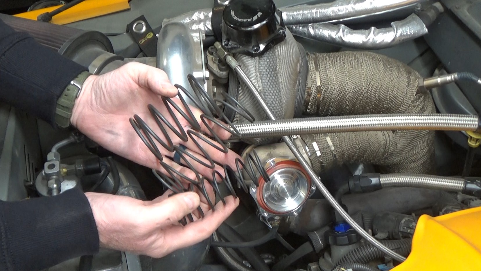
MAKING MORE BOOST: You can change the spring in the wastegate. My wastegate in my ’61 Apache came with three unmarked springs. I am reasonably sure they are all around 5psi each. Stacking two springs would give me 10psi boost. All three would give me 15psi.
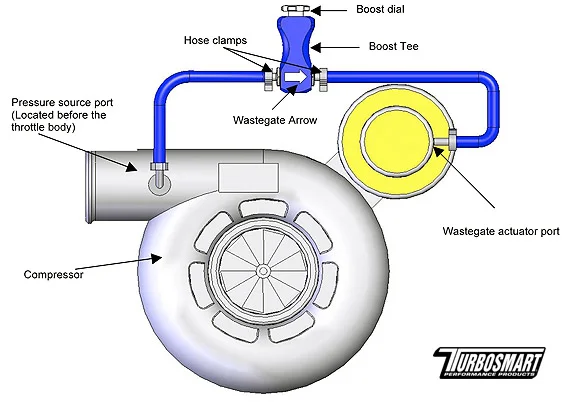
But what if I want even more? Let’s say a waste gate spring is set to open at 5psi of boost pressure… if you bleed off 3psi of boost on the way to the wastegate, then you actually have to make 8psi (5psi + 3psi) before the waste gate opens. This is good fun! This can bite you though, if you turn up the boost too high – more boost results in more exhaust pressure, which may start to push open the wastegate at higher RPMs, resulting in a drop in boost. Don’t try to run boost higher than double the spring rate. Try to run spring near the boost you want, and only “tweak” it with a controller: 1. MANUAL BOOST CONTROLLER: A “Boost Tee” (you can make your own, called a “Grainger Valve”) makes boost pressure have to overcome a wee spring inside before it goes to the waste gate (some designs just use a controlled air bleed to bleed off pressure). That means that the wastegate does not see ANY of the boost pressure until it is overcomes the wee internal spring, and it ONLY sees the boost that gets past the spring. Bleed off 3psi and you need to make an extra 3psi before the wastegate opens. Easy, easy, easy way to get more boost from a turbo.
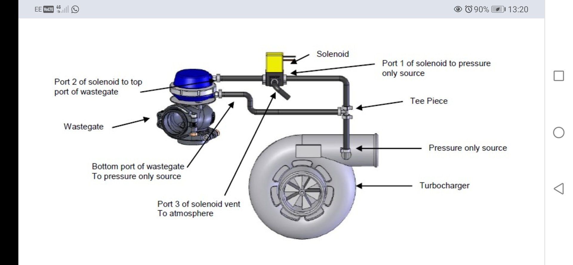
2. ELECTRONIC BOOST CONTROLLER A more precise method of controlling/maintaining boost uses a solenoid to add air pressure to the TOP of the wastegate solenoid which ADDS to the waste gate spring, creating more boost. Usually electronically controlled, it can be very very precise and consistent. While there are a variety of ways to actually plumb this, here is just one:
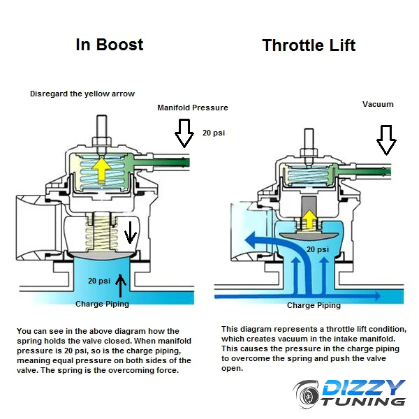
Blow Off Valve (BOV)Problem: closing the throttle under boost doesn’t immediately stop the boost – the backed up pressurized air gets chopped up by the compressor wheel and hurt the turbo! You can protect things by blowing off that boost when the throttle is closed: A valve upstream of (ahead of) the throttle plate that quickly bleeds off pressure spikes when the throttle is abruptly closed and you are under boost. Stalling the flow of air with a closed throttle makes the compressor wheel “break” the column of air, which springs back against the turbo where it gets broken again. This repeated (and diminishing) cutting sound is the “choo-choo-choo-choo” you hear. This is very hard on the bearings in the turbo. It sounds sweet, but is not good. CHOO-CHOO-CHOO-CHOO! A Blow-Off Valve is basically a device that plugs a hole in the intake piping before the throttle. The plug is held down and held closed by a spring that is strong enough to stay down and stay closed when the engine is running normally. Above the spring is ported directly to intake manifold vacuum so that both high engine vacuum AND high boost to push open the plug to vent the boost to atmosphere.
When the intake system gets backed up with boost, the BOV prevents damage to the turbocharger bearings by bleeding off the pressure. These can bleed noisily to atmosphere (Awesome!), or back into the inlet side of the turbocharger (Boring!). It is nothing more than a pressure relief valve that opens when it senses the vacuum of a closed throttle and boost in the charge piping. FFFFSSSSSHHHHHHHHH! By-Pass Valve (BPV)EFI systems running a MAF (Mass Air Flow meter) must have the blow off valve feed back into the inlet side of the turbocharger (after the air flow meter) or the fuel metering will be wrong – the ECU reads how much air the engine ingests according to MAF and fuels accordingly; the ECU won’t know we blew off that air (BOV style). If you blow the air back into the turbo but after the MAF, according to the ECU, that air never left and the turbo will not draw more air through the MAF and the engine will not provide too much fuel. Do you HAVE to run a BPV? No. But it’s better if you do. Hmmm…. I wonder… if you just blow it to atmosphere and let the engine over-fuel…. would you get flames out the tailpipes? If it blows to atmosphere, it’s a Blow Off Valve. If it pipes it back in, it is really more of a By-Pass-Valve.
|
|
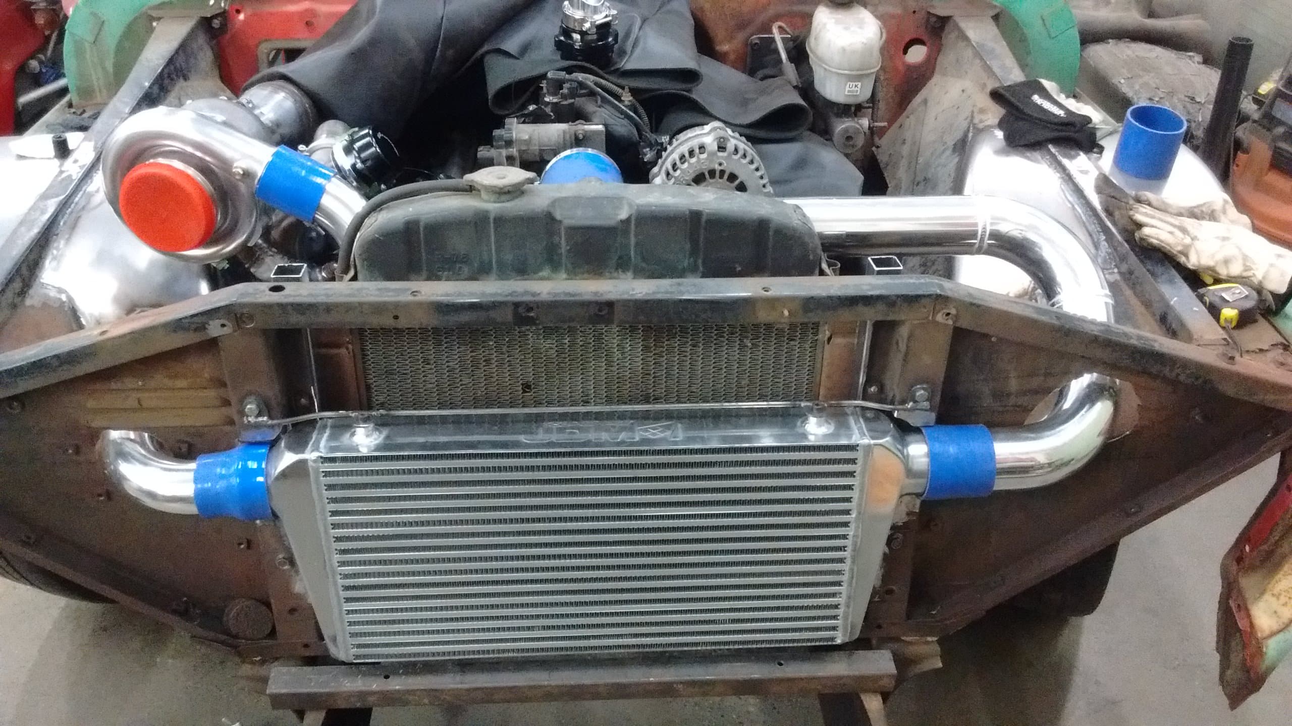
IntercoolerDo you remember radiators from Cooling System in Level 1? Do you remember that it has tanks on either end to receive and send the coolant? And that inside there are wee tubes to send coolant through wee fins to draw all the heat out of the coolant and into air? Same. An intercooler is just like a radiator, but for cooling the incoming air charge. Boost is sent into an end tank which then goes through a whole bunch of tubes, fins, and collect in another end tank. Not always found in a supercharged system (though they should be used), they help cool the incoming compressed air charge down significantly. They are often air-to-air (moving air takes the heat away), but some are air-to-water (the unit is sealed, and uses water to take the heat away to a remote mini-radiator). Intercoolers reduce overall boost slightly because they are, in effect, a restriction in the airstream. Air-to-water intercoolers are more efficient, however they add an extra level of complexity. ALL intercoolers will cost you some flow/boost. The more internal tubes, the better it cools – but tubes reduce flow, which cuts into boost. You lose 0.5psi for every 90° bend the air has to go around. I lost 3psi boost through the intercooler and piping on my ’61 Chevy Pickup. I had my wastegate connected to the turbo outlet (as recommended), not the intake manifold, and while the wastegate opened at 5psi, only 2psi was actually making it to the engine! If I crank the boost up higher to make up for the intercooler loss, I lose even more boost at higher rpm’s because more boost = more volume = more intercooler loss. It is surprising just how quickly 5psi becomes boring. As of this writing, I’m at 9.5psi (and I built the engine for 22psi: 900hp!) Intercooler size and effectiveness can be calculated, and their effect on temperature (our enemy) incorporated into our calculations. Cool air is DENSE air, and cooling the air with an intercooler allows us to flow MORE air into the motor while running less boost (as there is less of a “heat” problem working against us). Generally speaking, try to fit the BIGGEST, THICKEST intercooler you can fit. Cut things to fit the biggest intercooler you can.
Water (or Water/Meth) InjectionA method of cooling the incoming air charge by spraying a fine mist of water (or water/methanol) into the air stream. You’d think this would be detrimental – I mean, wouldn’t water sprayed into the engine make it rust? Or be incompressible and break something? No – sprayed into hot pressurized air, it evaporates almost instantly, which absorbs heat out of the air stream, thus cooling it down. Inside the engine it is SO hot, that is isn’t ever going to stay moisture. And we’re not really spraying that much water into the air stream. The water/meth evaporates almost immediately, taking with it some heat. It actually significantly cools the incoming air charge. This is used to help reduce detonation. While you would think that adding water would reduce power, the cooler intake charge (and the reduced chance of detonation) more than makes up for it. A higher quantity of Methanol in the mix can aid in performance too, it’s essentially a high-octane fuel. Recommended as you approach 15psi boost. Some folks even use Washer fluid. I’m using a Snow Stage 1 Methanol injection kit, spraying blue -40°C washer fluid at 7psi and up. In the datalogs you can actually see the intake air temps drop when the meth comes on. You use a larger spray nozzle with higher horsepower and boost levels.
|
|
Selecting a Turbo |
|
|
When selecting a Turbocharger (or even a supercharge), we look at desired power, pressure ratio, temperature gain, and density ratio. Since a turbocharger builds up based on engine load (exhaust flow) not rpm, we really need to look at at least three different rpm points and find a compressor that suits: Start of peak torque (say, 3500rpm) End of peak torque (say, 5500rpm) Redline (say, 7500rpm) Turbochargers are “mapped” according to what they can flow. Within a certain range they are efficient and produce a minimum of heat. Running a turbocharger outside of its “map” can result in producing too much heat (you’re spinning it too fast), or the turbo going into “Surge,” or “Choke.” Surge: kinda where the turbo does “The Hippy Shake-Shake” where the turbo moves more air than the engine can take, and the boost starts backing up into the turbo, slowing it down or stalling it. (This IS the “choo-choo” sound!) ie: the turbo is too big Choke: the turbo itself becomes a restriction, where the engine actually needs more air than the turbo can provide. ie: the turbo is too small A/R Ratio: This is the ratio between the exhaust input Area (A) and the radius (distance) of the centerline of the turbo to the opening (R). A small A/R (ie: 0.82) is a smaller opening, making the turbo spool faster and be more responsive, resulting in more torque, whereas a larger A/R (ie: 1.21) will spool slower and be less responsive but will breathe better and increase high speed power. I recommend a small A/R ratio for street vehicles
|
|
Compressor Maps |
|
|
A compressor map provides enough information to help you properly select a turbocharger. It is very important that your turbo is properly sized or it may not work safely or effectively, if at all. Keep in mind you may have to do some conversions to read the map you have, as there are many different units for air volume used. Check out this map. It uses Pressure Ratio and Air Flow to find efficiency. If you look at a Pressure Ratio of 1.60, and an Air Flow of 25lbs/min, it ends up smack dab in the sweet spot of the turbo. If at all possible, you want to be in the center of the graph at all three rpm (boost/flow) points. While you can begin to venture a bit outside, you MAY NOT let the turbo run outside the Surge Limit on the left. This is death for the turbo.
One other thing, our flow calculations are in CFM, but some compressor maps are in lbs/min. You will need to convert this (multiply CFM by 0.069). If we use the data from our Supercharger example, we found that to produce 320 horsepower from a boring old 302 Ford, we needed a Pressure Ratio of 1.87 and 718cfm of Air Flow: Pressure Ratio = 1.87 Air Flow = 718cfm (50lb/min) Looking at the compressor map for the T04 turbocharger (RED dot, below), we find that the turbo is way too small for a 302 engine, as it would be running below 60% efficiency, and thus producing a lot of heat instead of boost.
If we run TWO of these turbos on a 302 (368cfm each, 25lbs/min, GREEN dot above) at the same Pressure Ratio, two turbos would work, but would be a touch on large side. We could go back and reduce the Pressure Ratio, which would also reduce the Flow Rate, to get the turbo to work more efficiently on the 302. You may be interested to know, that 718cfm from a turbo into a 302 would produce 575hp – turbos are so much more efficient than a supercharger. To choose a turbo for YOUR vehicle,
|
|
MAKING IT WORK |
|
|
Whether you’re boosting or spraying, you gotta make it live. Adding power to an engine is kind of like being a Meth Addict: It’s hard on your body Overdoses can kill If you’re moving more air, you need to increase the amount of fuel. Since the combustion chamber is DENSELY charged, combustion will happen more quickly, so you need to reduce the amount of spark timing to avoid detonation (where the fuel explodes uncontrollably rather than burns). FuelFour things you should do to increase fuel delivery to your boosted engine are: Increase the size (and/or number) of Fuel Pump: Especially when running E85, which almost doubles the amount of fuel volume you will burn. If you want 1000hp, you’re going to need a fuel pump (or fuel pumps) that can flow 1000+hp of fuel. (I’m running a Dodge Hellcat fuel pump in my boosted ’61 Chevy) Increase fuel pressure as boost increases: Theoretically more fuel is going to get pushed out when the injector opens. This is might usable up to about 9psi boost, but likely will still not flow enough fuel. Often times an increase in pressure does NOT increase the volume of fuel as much as you want. Boost-Controlled Fuel Pressure Regulators are available, which increase fuel pressure as boost pressure increases (30psi fuel pressure cannot spray anything against 30psi of boost, the boost will push the fuel back into the pump). (I added a boost-referenced fuel pressure regulator to my boosted ’61 Chevy) Increase fuel injector size: Certainly provides more fuel per injector opening, but a large injector may be hard for the computer to cycle slow enough for a quality idle (too rich – too much fuel coming out at idle). Many injectors are interchangeable, so you just need to find the right size injector in the injector shape you need. You DO have to tell the computer what size the injectors are, or it will just be rich everywhere. (I “de-capped” the injectors in my boosted ’61 Chevy – changes the flow from 24lbs/hr to 73lbs/hr) Increase Injector Pulse Width: The injector is just opened longer. Usually the ECU does this for you. This is effective until the injector is 100% open and there still is not enough fuel. This requires additional circuitry or a reprogrammed ECU. You really should not exceed 90% duty cycle, and 80% or less is better. While I built the engine in my boosted ’61 Chevy to handle 22psi boost, the computer can only understand 2-Bar MAP, that’s a paltry 14.7psi boost or 800hp, and so disappointing it’s hardly worth mentioning. Less common, but sometimes done: Increase the number of injectors: Ideally controlled by a separate controller, or by an alternate or reprogrammed ECU. I have seen an extra set of injectors activated at boost, so you can still run the factory injectors for idle and off-boost. IgnitionThe three effective methods of allowing the ignition system to work effectively on a boosted engine are: Voltage: Most modern ignition systems have enough juice to ignite a supercharged engine up to around 6 to 8psi. Above that a much higher voltage ignition system is in order. Spark Plug Gap: Enough boost can “blow out” the spark, so most folks decrease the plug gap to make it easier to spark. 14psi and under, around 0.028″ gap 15psi to 20psi, around 0.025″ gap Above 20psi around 0.020″ gap Heat Range: Spark plugs one or two heat ranges colder will reduce the chance of pre-ignition, reducing the chance of a hot spark plug accidentally igniting the mixture at the wrong time and causing damage. Ignition Timing: Must be reduced as boost increases. There are aftermarket stand-alone or add-on systems that do this, and modern factory ECUs can often be re-programmed. Typically you want retard (take away) 1° of spark timing for every 1psi of boost, but you can’t retard the total timing too much or the cylinder will get too hot (fire chasing the piston and heating the cylinders) and things melt. If, however, you don’t retard the timing enough and the mixture begins to burn on its own (without the spark), cylinder pressures can get too high and Detonation can occur = broken pistons and bent rods.
Ring GapsYou really need to open up the ring gaps if you want to run silly boost. Piston rings expand under the high heat of making power, and they expand more when you are using a power-adder like a blower or a turbo or nitrous. If the rings expand enough to butt together, they “buckle” and break the piston. Up to 15psi 0.0055″ per inch of bore (that’s 0.022″ for 4″ bore) 15 to 30psi 0.007″ per inch of bore Above 30psi 0.008″ per inch of bore
|
|
WHAT WOULD WELLWOOD DO?(WWWD?) |
|
|
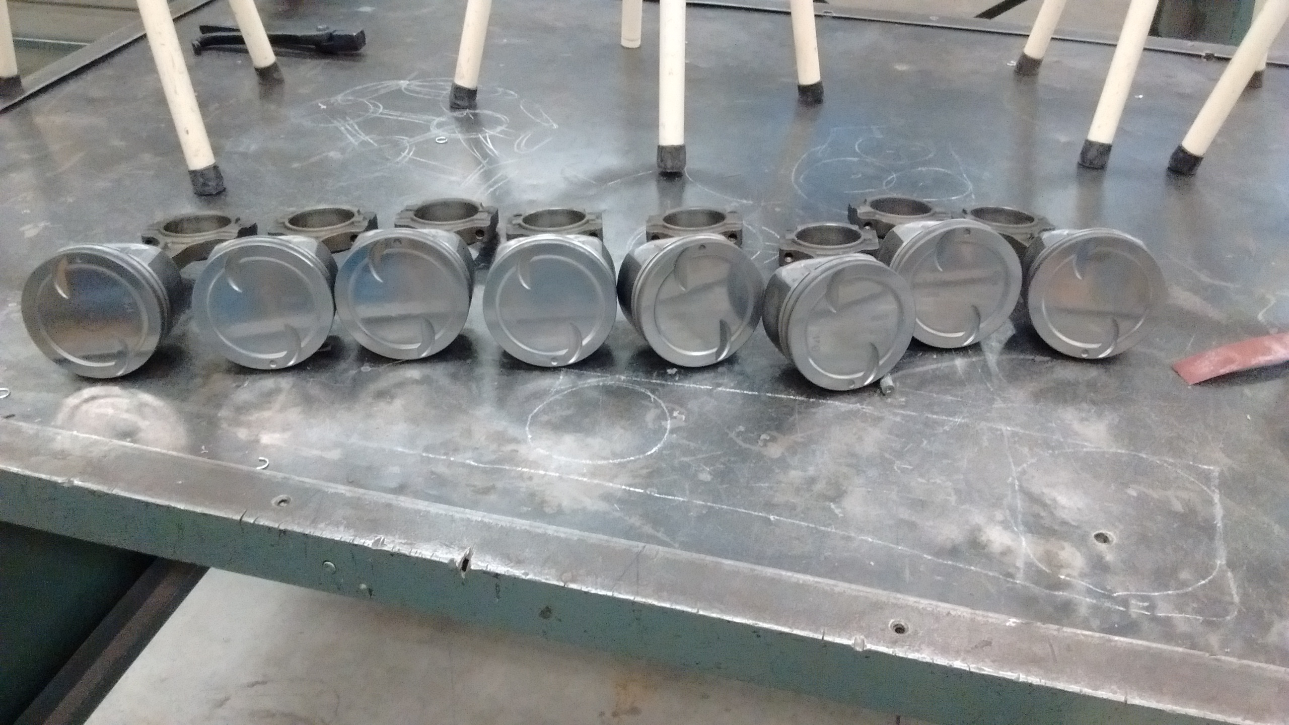
This Section Currently “In Development” I built a turbocharged 6.0L Chevy LS motor for the 61 Apache. The goal is 650 horsepower at the wheels (but I fueled to to 1000hp at the crank because “inevitable;” power is like Crystal Meth – you never get that same high again). Things I have done so far: ARP Head Studs – much better clamping force for the head gaskets than using bolts (factory bolts are “torque-to-yield” and are not reusable). LS9 Head Gaskets – these are from the factory supercharged motor in the Corvette; they are designed for boost. Ring Gaps Increased – 0.007″ per inch of bore. These are opened up significantly so they do not butt together when they heat up from my intended 22psi of boost. This will also increase blow-by in non-boost conditions, but magic always comes with a price. Factory spec ring gap: 0.014″, Now: 0.026″ top, and 0.028″ second. Polished Combustion Chambers – all potential sharp edges removed for zero chance of hot-spots causing detonation.
Polished Piston Tops – all potential sharp edges removed for zero chance of hot-spots causing detonation.
Colder Spark Plugs – reduces the chance of a hot running plug causing detonation. Smaller Spark Plug Gap – easier to ignite under boost. Factory spark plug gap: 0.040″, I’m running 0.024″ Stronger Valve Springs – factory valve springs are less effective (less strong) at closing the valves against high boost. Also, boost means you’re still making power at high RPM. These springs are good to at least 7000rpm De-Capped Injectors – This removes the factory spray diffuser and increases the injector flow over 250%. Some tuners are totally against doing this, but I’ll tell you it does work. This should be enough for 1000hp at 85% injector duty cycle. 3-Bar MAP Sensor – Factory MAP sensor cannot read more than atmospheric pressure (1-Bar/100KPa/14.7psi), so you need a sensor that can. If I go over 2-Bar at all (14.7psi boost), I’ll wish I went 3-bar. Go big or go home. A 3-Bar MAP sensor could allow you to run 30psi boost, potentially 1100hp+ in my case. Addendum: My PCM OS cannot go more than 2-bar/14.7psi boost; I should have bought just a 2-bar MAP for better resolution) Tune – Factory ECU hacked to manage the engine at full boost, with bigger injectors. More fuel added on boost, spark advance taken out on boost. Keeping the factory tune off-boost so I can mooch off all the engineering GM did for the base engine. Beefed Up Heavy-Duty Transmission – if you don’t break traction, you’ll break something else. Ford 9″ rear axle – Almost indestructible; if you don’t break traction, you’ll break something else. Limited Slip Differential – Because this truck would otherwise be severely “traction-limited.” Methanol Injection – Because sometimes doing a little Meth is actually good (it lowers intake air temperature, and increases octane). Think of it as “safety” for the engine. My kit will start spraying windshield washer fluid into the airstream starting at 7psi boost. You can physically see the IAT drop 15° under boost.
|
|
WHICH ONE IS BEST??? |
|
|
Depends what you want. Good video comparing Roots Blower, Screw Blower, Centrifugal Blower, and Turbos:
Which one do YOU want?? |
|