[ Start ] [ Index ] [ Parts List ]
Finishing Details
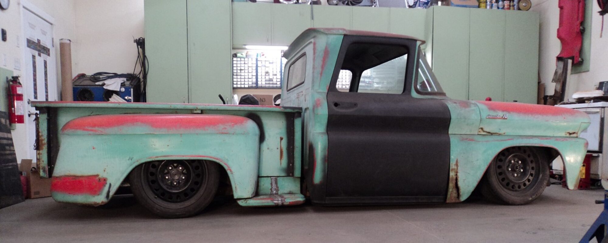
With it running and driving, we work on making it the most enjoyable. And reliable.
Way back, I added extra slots in the dash to fit two 5.25 coaxial speakers.
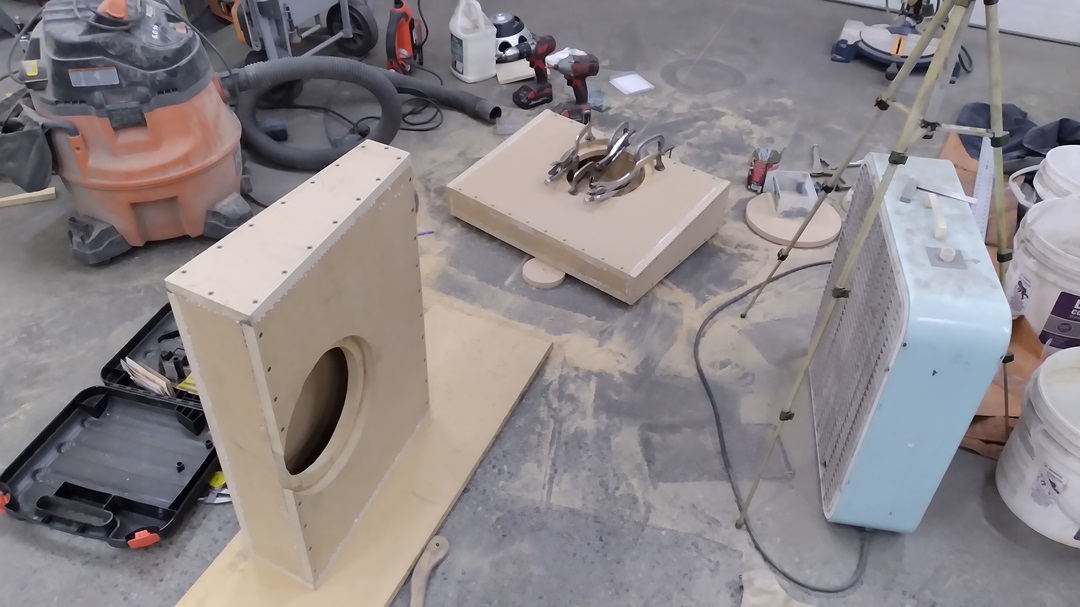
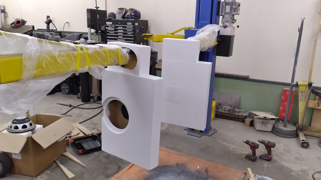
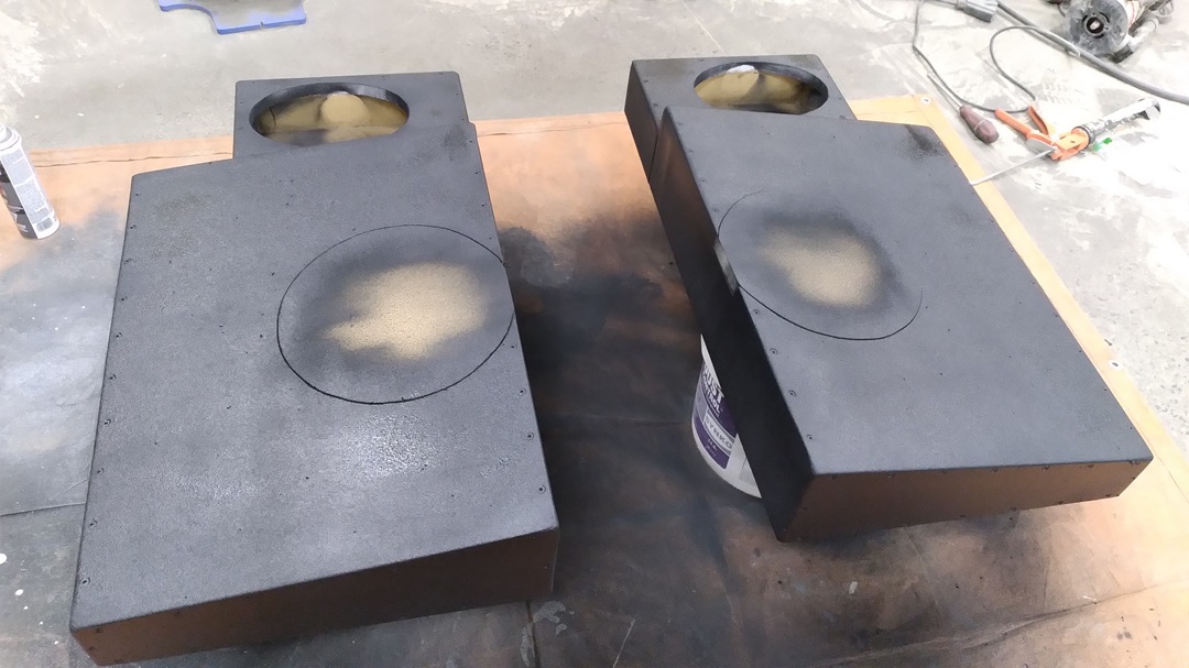
Not much in the way of low/mid frequencies. So…. SPEAKER BOXES!
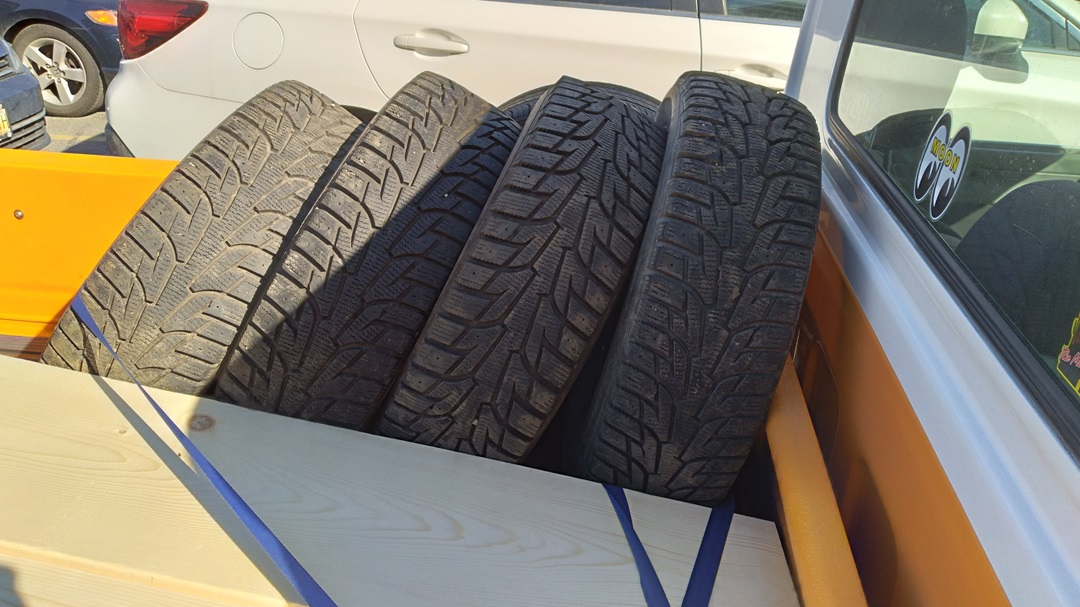
Trip to Home Depot for some garden boxes, and picked up a set of used tires to bring my son’s ’68 Catalina home.
Second tank of gas so far this year. Up to 9psi boost now. Oh my giggity goo! Fun fun fun.
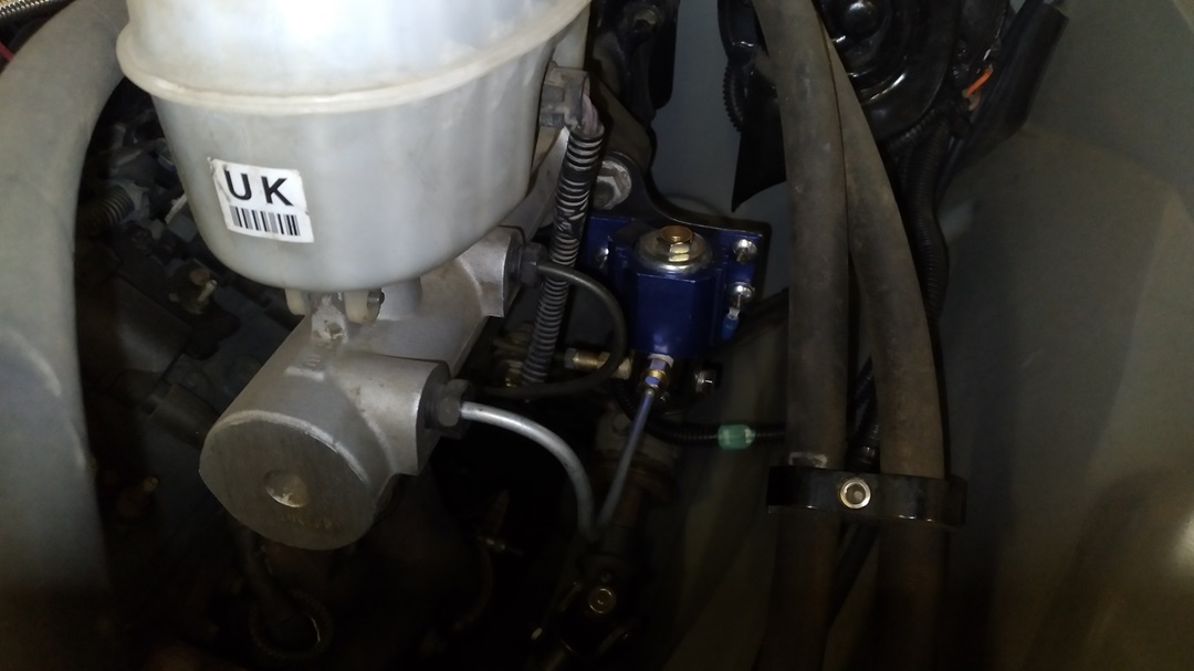
And the linelock popped, puking brake fluid on the exhaust:
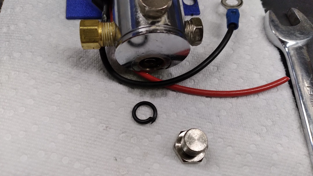
EPDM o-rings are brake-fluid-friendly and can be found on Amazon, so a new o-ring and a reassembly and we’re good to go.
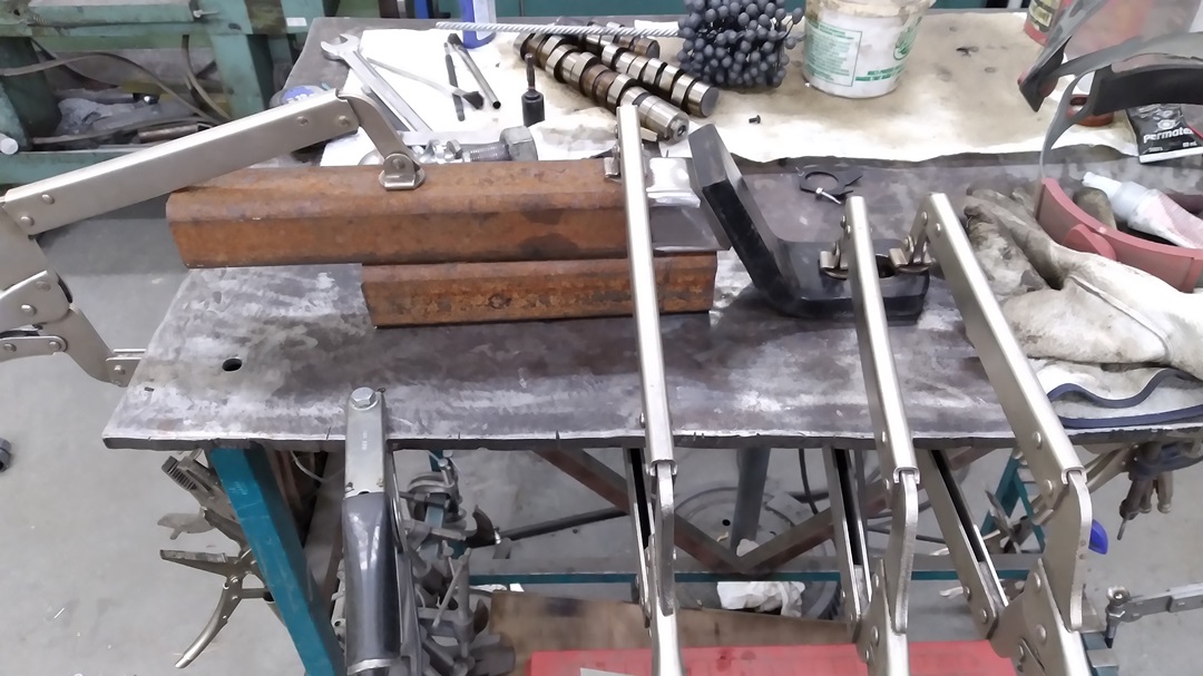
I bought a trailer, since I sold my last one with the matching truck. It needs some love, but more importantly I need the right length ball hitch. In this case, that’s 14″ to clear the sexy bumper.
Mocked up for welding:
And now that I’m making one, I see that they are actually available online….
I also bought the cheapest catch can on Amazon, because I’m pushing oil out of the engine under boost.
Turns out, it’s also the smallest catch can.
Not really a problem, and it actually works out good, because I altered it to act as a zero-maintenance oil-separator and drain the oil back into the crankcase.
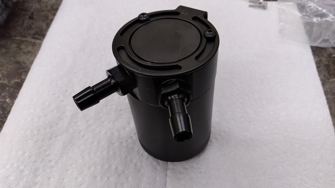
I plugged the right side port and drilled out the threaded drain on the bottom and welded a -10AN bung so the can is filled from the bottom. I also welded a -10AN bung on the left side port which I also ported internally. This is mounted using one of the heater box screws, a bracket, and a hose clamp. Then I made up new AN breather lines.
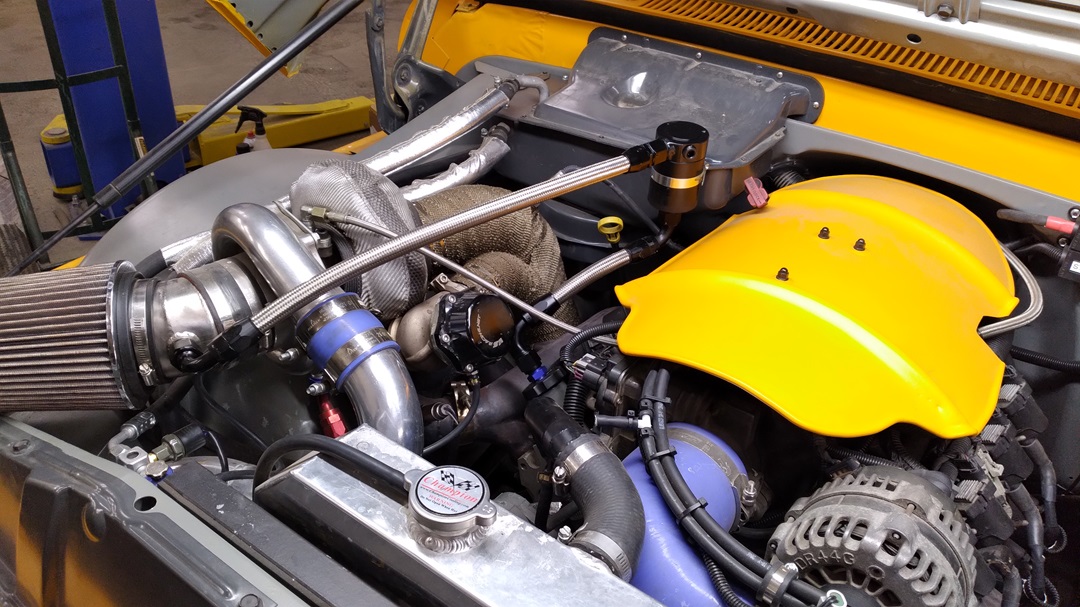
Operationally:
- “Blow By” gets sucked into the intake manifold at the back of the driver’s valve cover.
- In order for that air to move, fresh filtered air comes from pre-turbo, through the catch can, and into the oil fill cap on the driver’s side.
- Under BOOST, a one-way check valve at the intake manifold stops the crankcase from being pressurized.
- Crankcase pressure escapes through the -10AN line out the oil cap to the catch can, oil is collected, and theoretically just “blow by” is fed to the turbo and back into the motor.
- Off-boost, collected oil drains back into the engine.
In theory, at least.
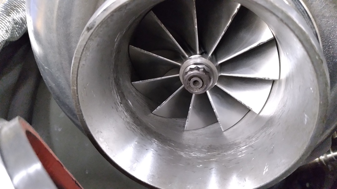
SOMETHING WENT BANG!
And some poop came out.
Turns out the engine sucked apart the Edelbrock air filter, the metal cap inside went into the turbo, and I’m hoping didn’t do too much damage….
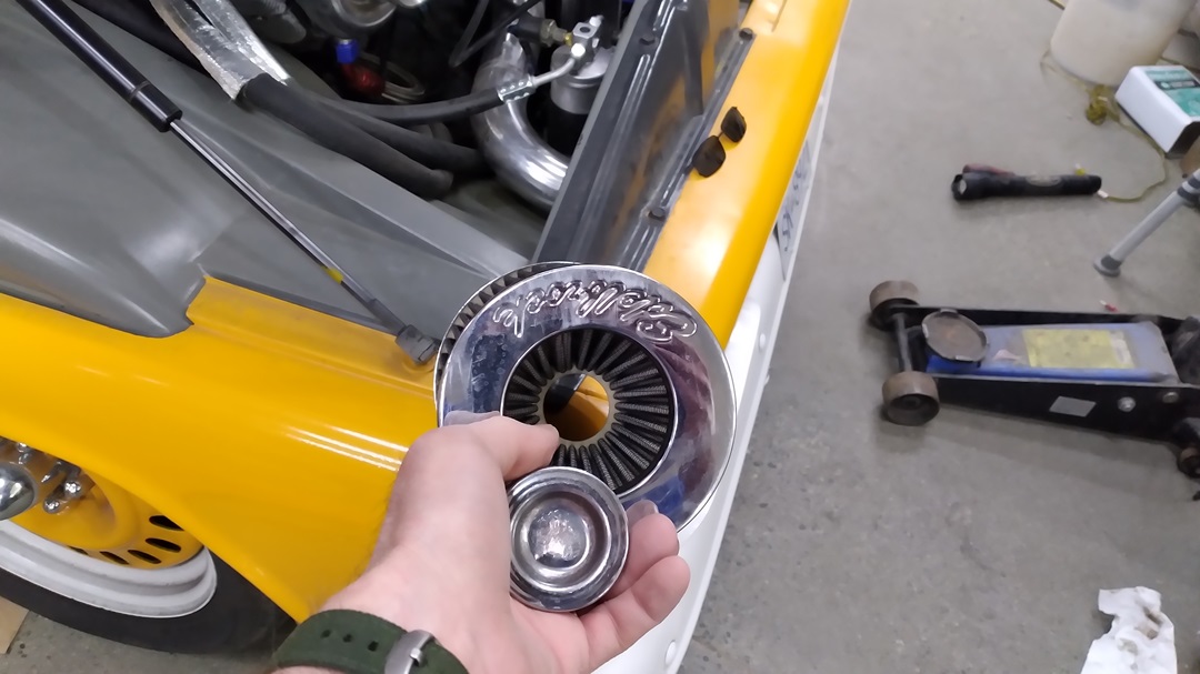
Off to LordCo tomorrow to see if I can get a K&N that DOES NOT have a suckoffable cap inside.
New K&N filter installed, off Amazon, with a solid rubber end cap.
This just in: 13.75mpg (US), 20L/100km – as long as I stay under 10inHg and never accelerate. At. All.
I fueled up with Chevron 94 yesterday. I’ve been tuning on 91, but run 94 for a bit more safety. We have no E85 here. 94 was $2.049/L. That’s $7.76 A GALLON
$7.76 A GALLON!!
You can see why I have a Hyundai Accent now, eh?
This is an LQ4, pushing a brick. A brick in the shape of a parachute. A 2003 Silverado with a 6.0 is rated at 10mpg city, 11mpg highway.
I’m doing REALLY good, now that I see that.
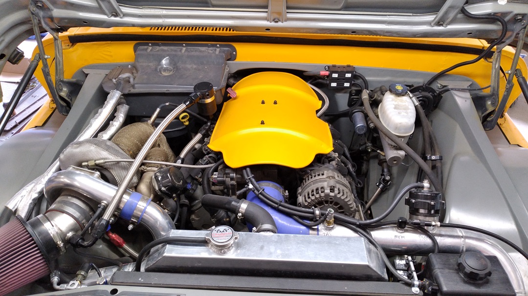
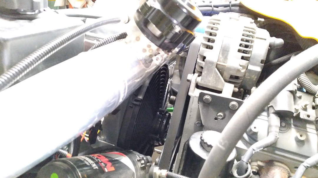
COOLING ISSUES
On the highway, it’s fine, but in traffic, in the summer, at 38°C, with the AC on, it’s not.
The rad core is 22×19″ in size and rated for 700hp. I have one $100 17″ American Volt electric fan, zip-tied directly to the radiator. This cools ONLY a 17″ circle minus the hub of the fan area, inadequate when standing still. The fan is rated at 130W, which should pull about 11Amps of current.
I ordered a $360 “Be Cool” 16″ fan that is actually make by Spall, which draws 26Amps.
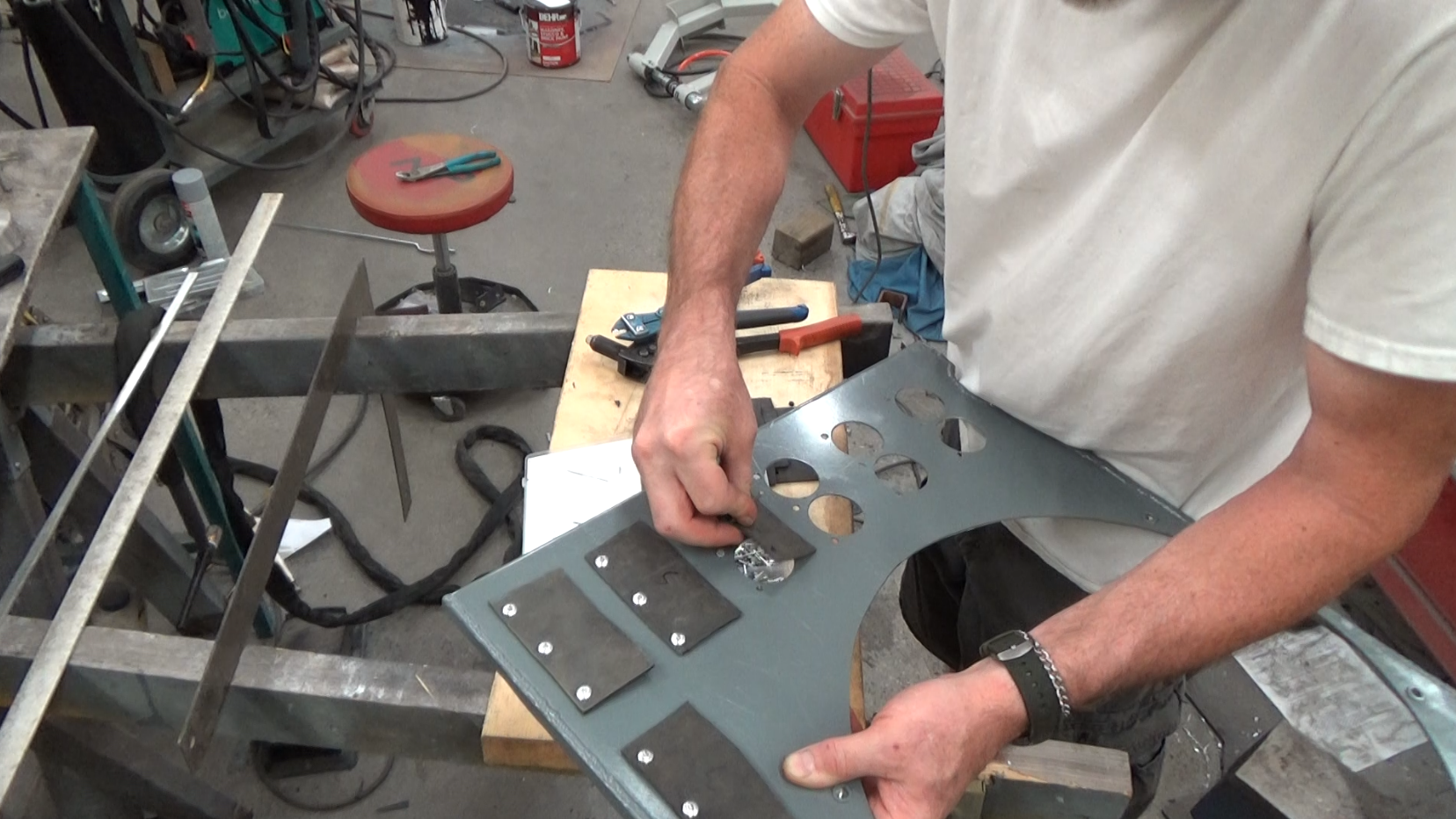
Excitingly, the blade and hub protrude past the mount, necessitating a raised mounting. If I’m going to raise it at all, I’m going to build a shroud. A shroud should encompass the entire core so the fan can draw air past the entire core. Which I fabricated.
On the other hand, fully shrouding a rad reduces the amount of air that can pass through the rad at speed. To fix this, I made nine 2″x4″ rubber flappers from a commercial truck tube, which “flap via three (each) 3/16″ pop rivets pulled NOT tight, so thay can move. These each cover a pair of 1-5/8” holes in the shroud. In theory, when the fan is pulling, these flaps are sucked closed, and when the car is at speed, air pressure forces the flaps open.
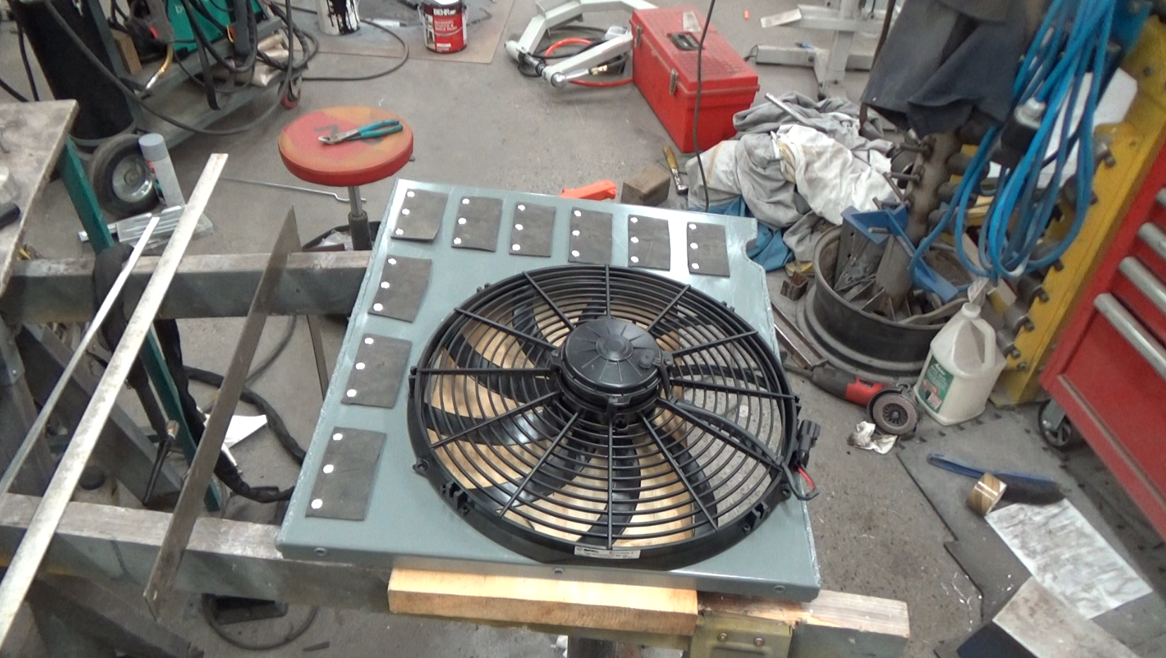
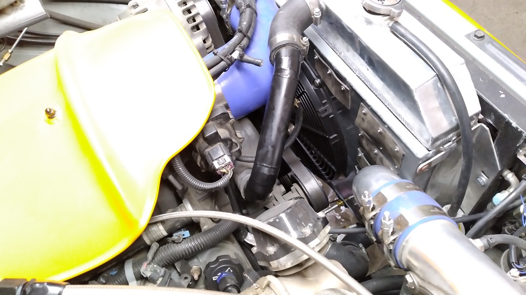
And boy does the completed unit almost fit for reassembly.
The result?
Needs more love….
In the video above, I go into more detail on the operation of the LS cooling system. It could be that the “old school” me is expecting lower operating temperatures, but these “new fangled” engines operate at higher temperatures.
In a nutshell:
SBC has the thermostat at the output, controlling the maximum operating temperature. Temperature sender is in the hottest point – the cylinder head.
LS has the thermostat at the input, maintaining a consistent operating temperature. Temperature sender is still in the hottest point – the cylinder head.
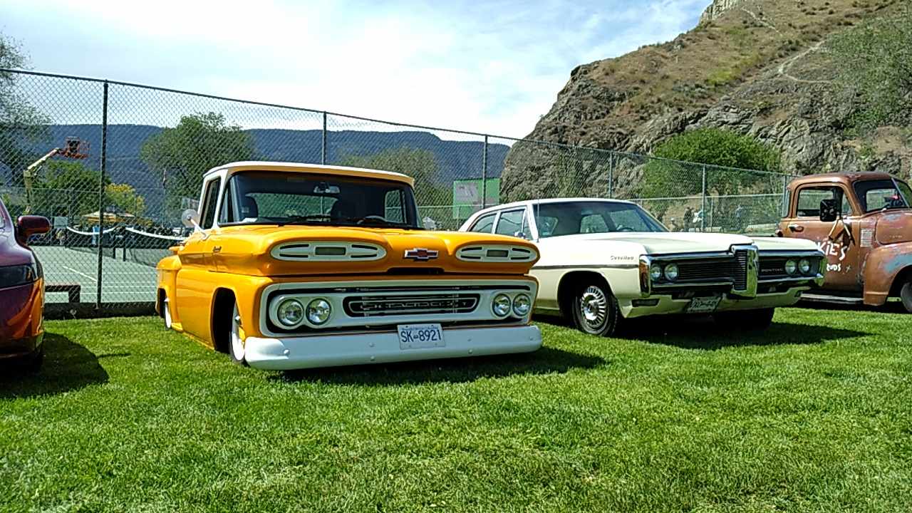
Knox Mountain Hill Climb Car Show with my son’s ’68 Pontiac Catalina:
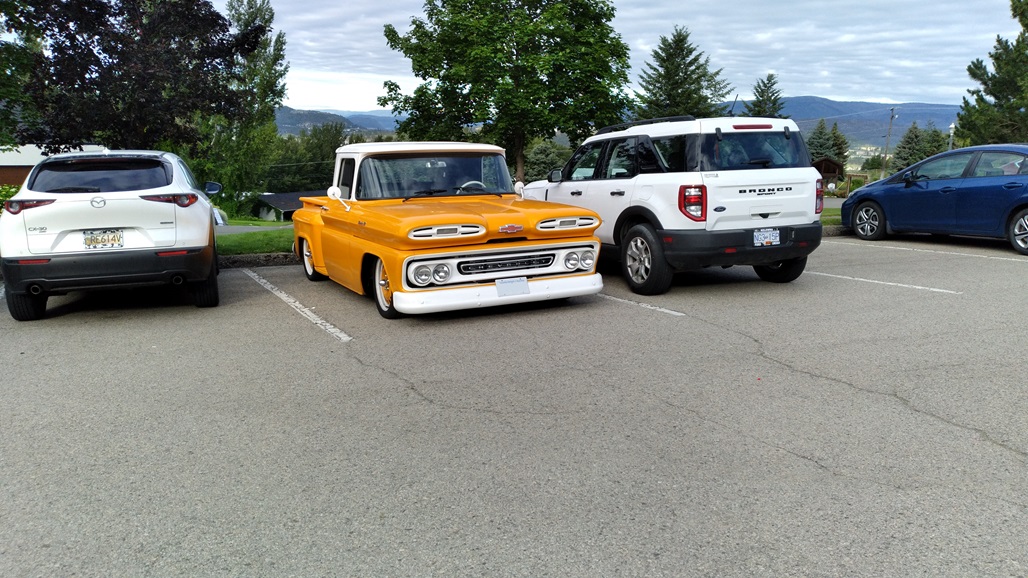
At our year-end staff meeting, cool in a sea of bland:
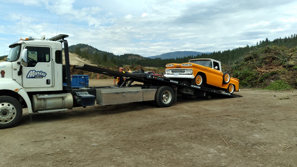
Mario’s Towing picking up the truck when the fuel pump wiring caught fire inside the gas tank:
Waiting for Mario’s Towing again to come pick my one-wheel trailer:

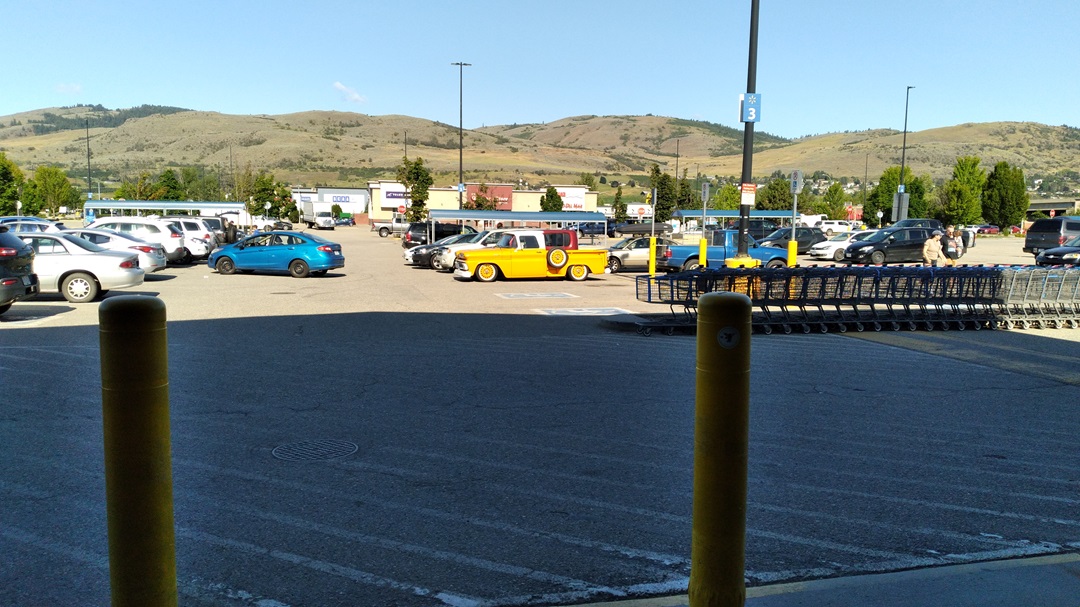
Shopping at Wal-Mart in Vernon:
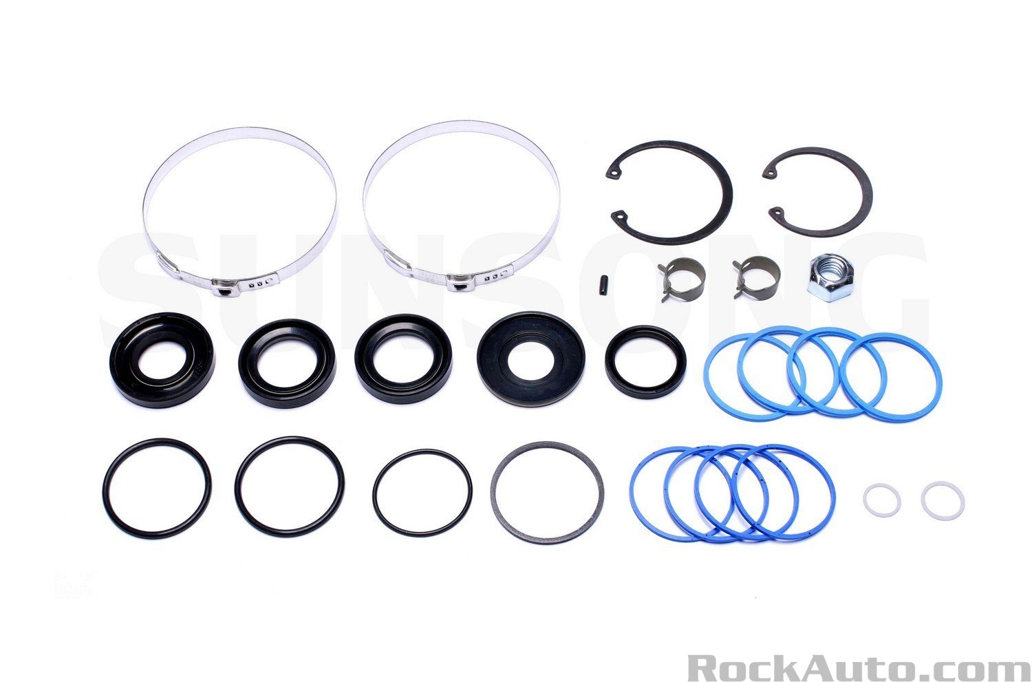
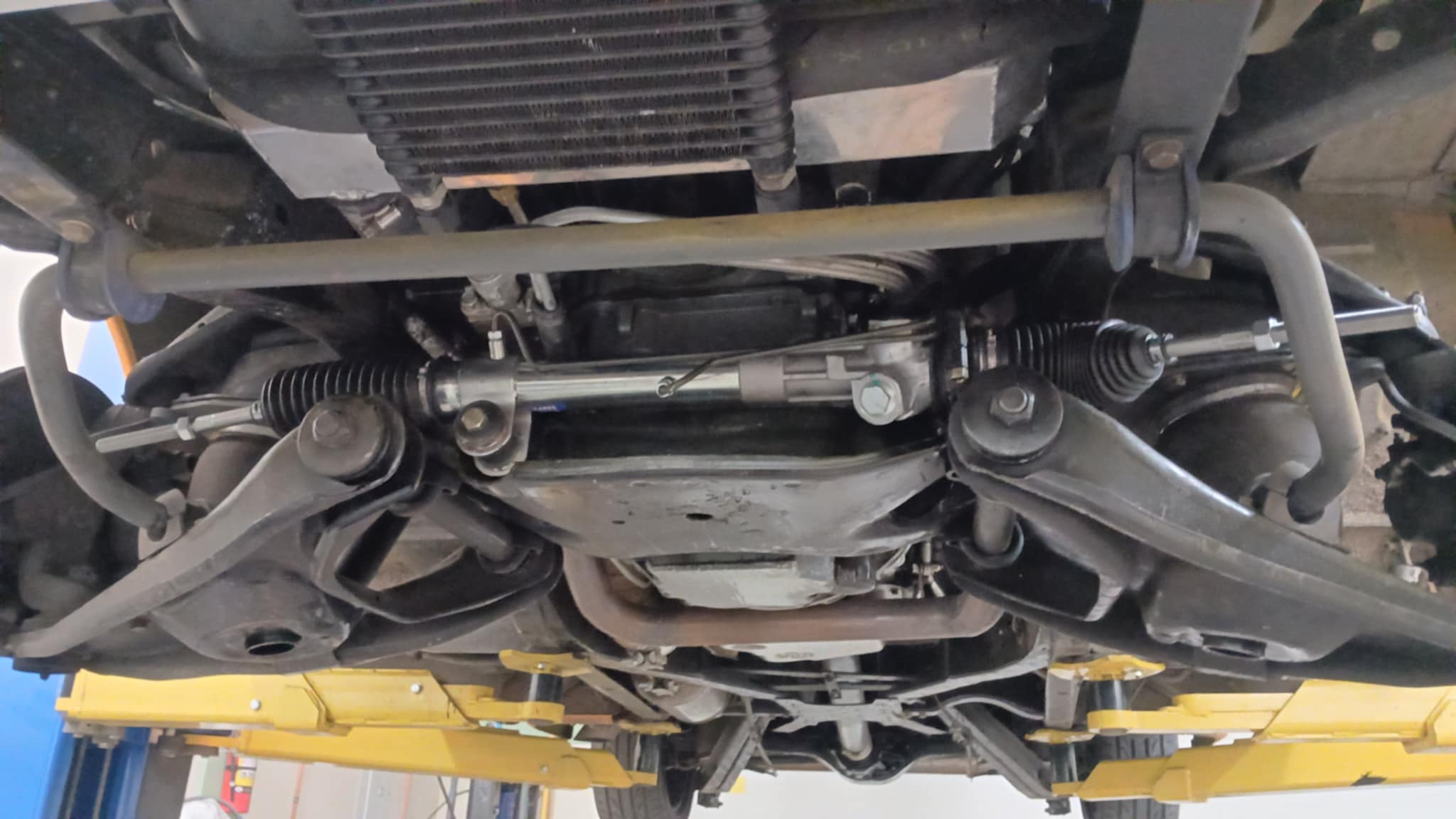
I ordered a rebuild kit for the steering rack as it is leaking (junkyard gamble). This was a failed attempt.
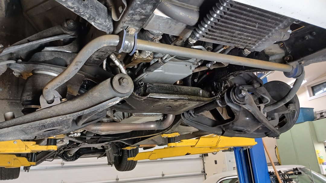
Rack out:
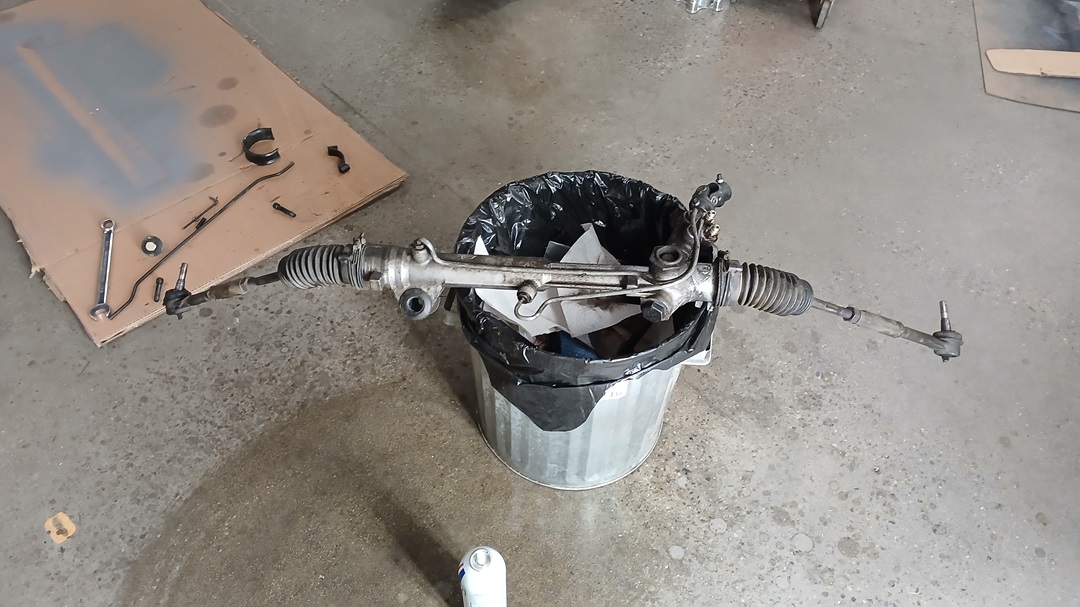
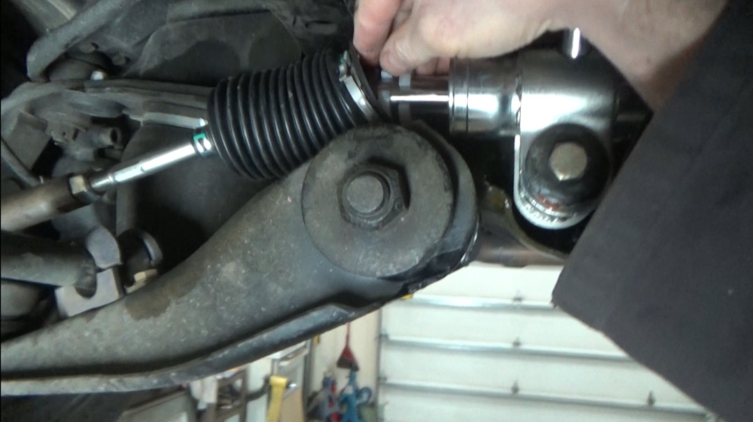
I may have damaged a bushing surface in the rack trying to unsuccessfully remove the center seal deep inside, so I bought a brand new Lares Mustang GT quick ratio steering rack from Rock Auto.
Zero leaks (yay!) but DANG is the turning radius even worse! This truck already turned like the Queen Mary (the ocean liner, not the Royal Monarch), but now it turns like the Titanic heading towards an iceberg.
I woke up screaming in the middle of the night with a thought….
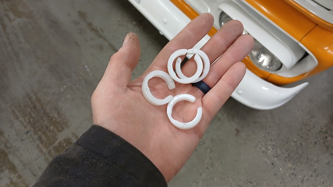
It turns out Ford puts these limiters inside which reduces the actual movement of the rack. Removing them turned my “quick-ratio” 2.5-turn lock-to-lock steering rack into a 3.0 turn rack. Just like I had. I feel cheated. But at least it turns.
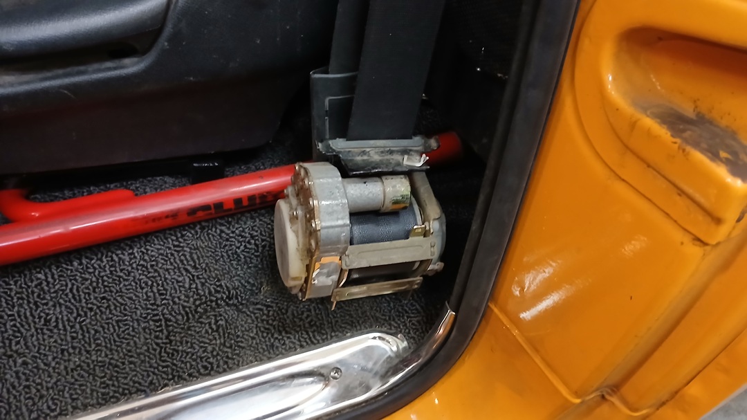
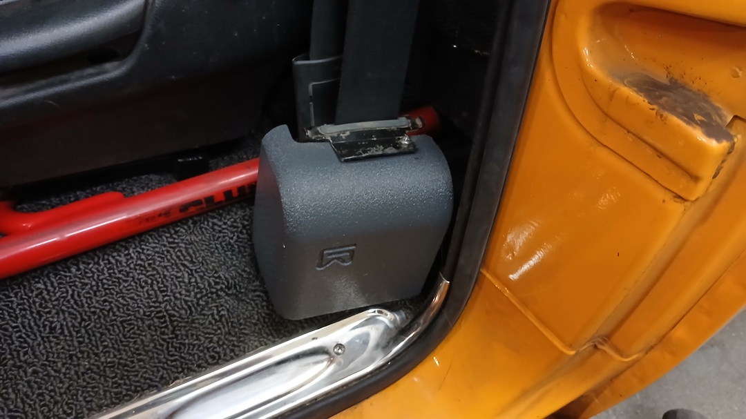
Finally got around to making seatbelt retractor covers. Honda Civic seat belts are usually tucked into the B-pillar. Here, they’re out in the open.
Found a neat feature on my 3D printer called Fuzz, which allows you to create a slightly textured surface, which looks a whole lot less like “fresh off someone’s home 3D Printer. I like it.
Old and busted:
New hotness:
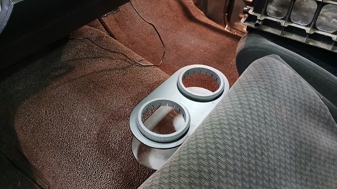
Added some 3D-Printed “cupholdermakersmallerinators,” because I apparently was a bit greedy in CNC-Plasma cutting my cup holder:
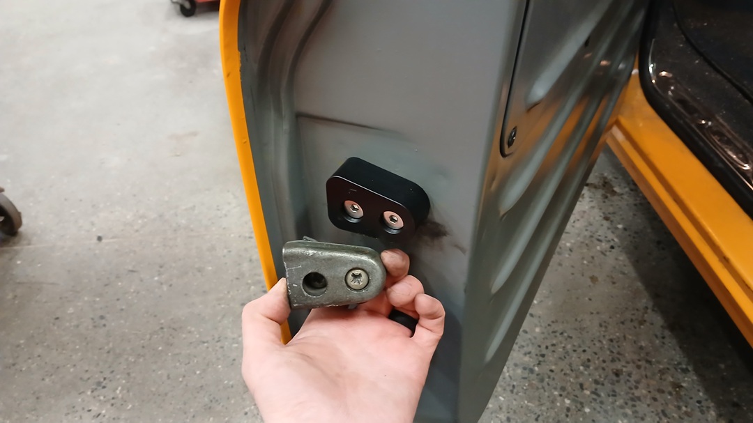
I also beat on the door seal flange and got the doors to close a bit better. Including removing the “sleeve” at the bottom joining the seal ends.
Replaced the faintly Dying Goose “whonk” horn with a new Flamm “Freeway Blaster” 133dB horn. Hid it behind the passenger side cowl fill panel. WAY better.
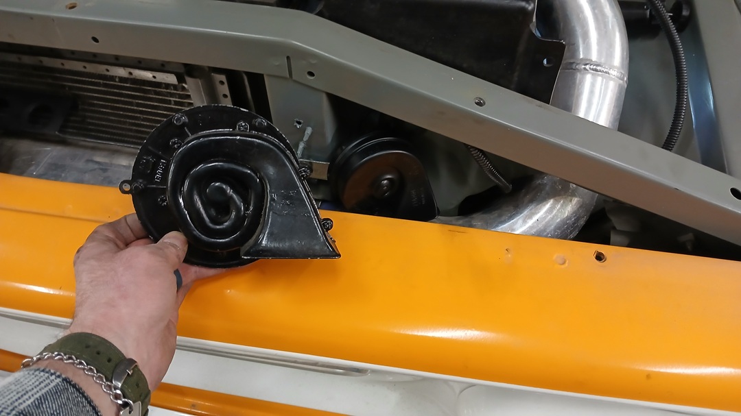
Oh my gosh you need to install these:
TUNING
I like tuning.
I started with the weakest wastegate spring (4psi? 5psi?) and tuned it – it was maybe 2psi getting into the engine. Then I started adding two clicks at a time to the Boost Tee and tuning each step until I got to about 9psi. Then I went to the next heavier spring, which was really no heavier. With the Boost Tee, I get a good initial boost, but soon the boost falls off as (I suspect?) the exhaust back pressure starts opening the wastegate: 9psi falling to 6psi.
So then I put two wastegate springs in that I thought were 4psi and 5psi, and got about 7psi on the gauge. So I tried what I thought were 5psi and 6psi and got close to 8psi on the gauge. It might just be all the springs are about 5psi, and I’m just going to lose 3psi in the intercooler/piping. All three should net me 12psi…. Maybe?
I moved the wastegate reference to what used to be the PCV “filtered air” port at the Throttle Body, thus eliminating the pressure drop through the intercooler/piping, and got 8.5psi peak falling to 7.8psi at the redline. Not bad.
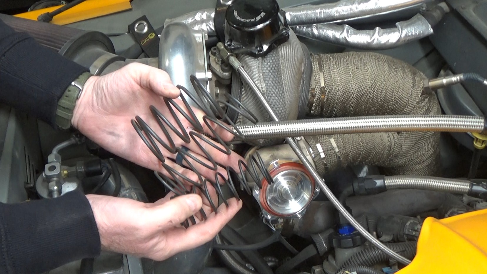
VS Racing wastegate appears to be a knock-off of an older Turbosmart Hypergate45. No idea what the springs are rated at. It might be that the inner is 4psi, the middle is 5psi, and the outer is 6psi. Or not.
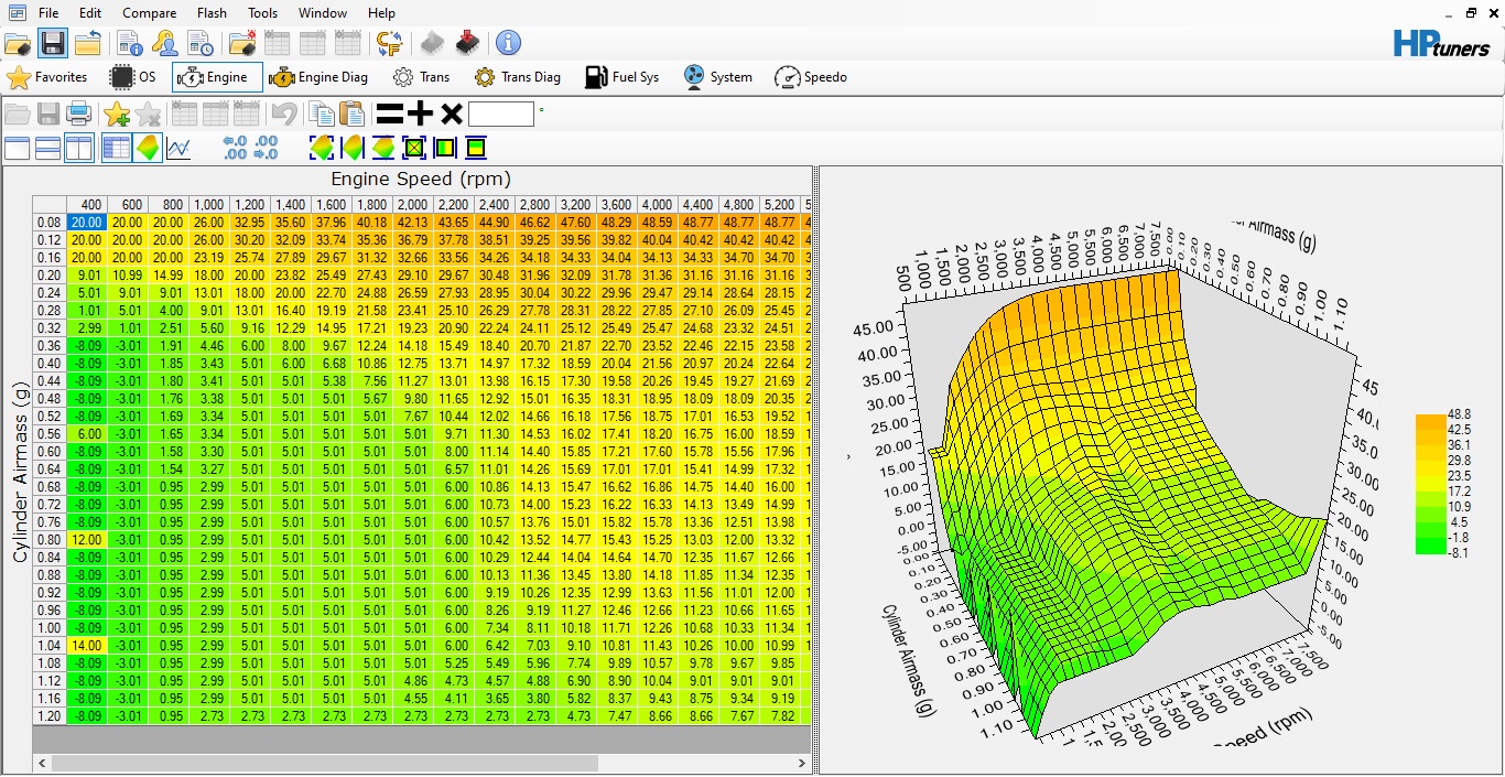
VE/SPARK TABLES
I spent some time smoothing the VE and SA tables. Only tuned up to about 9psi, so things are pretty fat above that for safety.
VOLUMETRIC EFFICIENCY (VE) Table (outdated):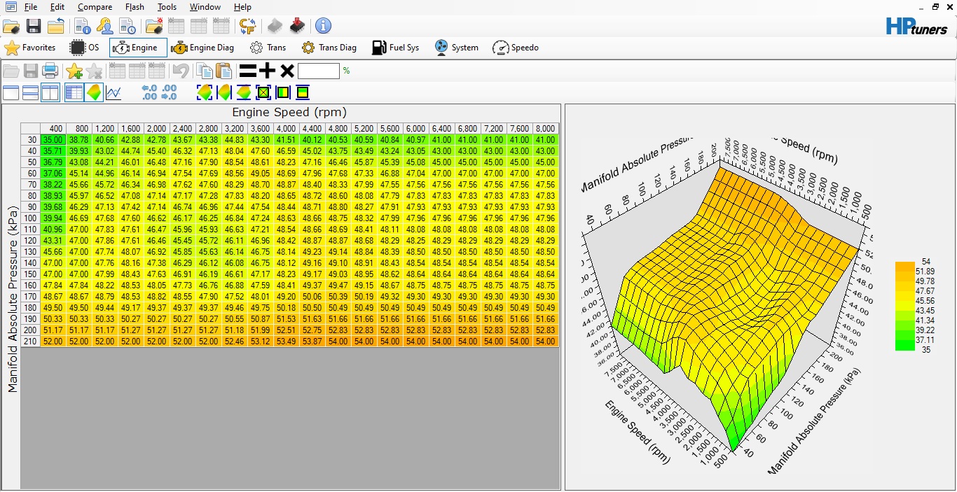
SPARK ADVANCE (SA) Table (outdated):
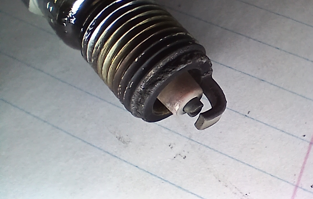
Plugs seem fine to me….
TRANSMISSION TUNING
With two wastegate springs installed, I learned something new.
The transmission would command an upshift at 5200rpm, but with the turbo, the truck was accelerating much faster than the PCM was prepared for. By the time the transmission got the job done, the PCM had already shut the throttle on me at my redline of 5600rpm. I dropped the 1-2 shift to 4750 and with the help of BlueCat on HPTuners, which now gets the shift physically done by 5400. It’s not a slow lazy shift at all – the motor just gets there fast!
BlueCat’s software also allows me to really play with when shifting occurs especially at light throttle, but allows me to tailor it exactly to what I want. I’m very much appreciative.
OVERALL
The truck is finally proving itself to be reliable. And at 9psi boost, a freakin’ HOOT.
There might not be much to report from here on in. I’ll continue tweaking and adjusting the tune as I go.
Thanks for tuning in! (haha. tuning. hahahaha.)
Fan Love
Videos I’ve found or have been shared with me: