Adapted from “RevIt Electrical-Lighting Plan” by Kyle Kondo, Feb 18, 2011
FIRST: You need a Ceiling
I’m going to go out on a limb, and assume you already have walls (kind of important for ceilings).
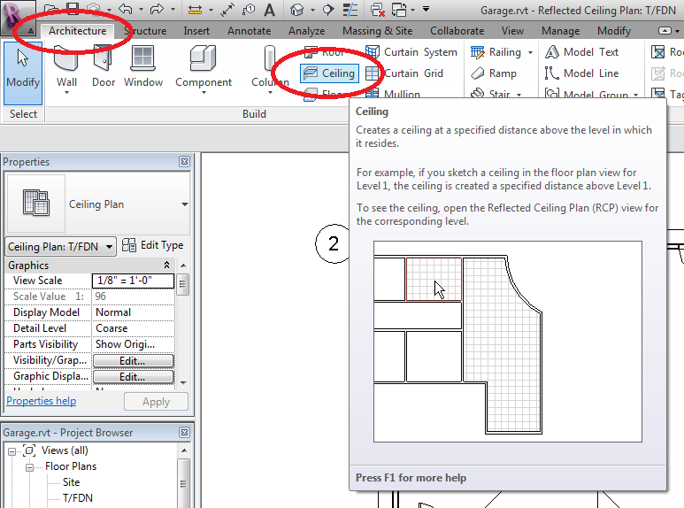
Double-Click the Ceiling Plan for the floor you are working on.
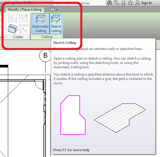
Click the [Architecture] tab of the ribbon menu, click [Ceiling], then pick either “Automatic Ceiling” or “Sketch Ceiling” depending on what you want to do.
Vaulted ceilings can be done, but you need to sketch each slope (and then give it a slope, much like a roof).
LIGHTS
Lights attach to ceilings – make sure you drew one! No ceiling? No lights!
The ceiling is the host object for any lights that you want to place. As long as you have a ceiling, just like the switches and outlets, you can use the Place Component command to insert lights. Place ’em where you want them! Don’t forget your exterior lights!
Work on your Ceiling Plan, not your floor plan.
Note that there are many options for the types of lights available. The type of light becomes more critical when you are creating rendered views of your structure.
Visibility Graphics & View Range
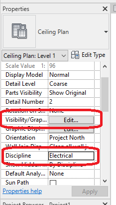
In the PROJECT BROWSER, pick the CEILING PLAN for the floor you are working on
In the PROPERTIES, scroll to find VISIBILITY/GRAPHICS, and click EDIT, and turn EVERYTHING OFF EXCEPT:
-
-
-
- Ceilings
- Electrical Equipment
- Electrical Fixtures
- Lighting Devices
- Lighting Fixtures
- Lines
- Walls
-
-
Also in the PROPERTIES, set the DISCIPLINE to “ELECTRICAL”.
RevIt doesn’t always let you see everything. By default, you see BELOW the ceiling (otherwise the ceiling will block your view of the walls), but ABOVE the wall sockets. That won’t work when we want to see wall sockets and ceiling lights!
To correct this, we need to set the VIEW RANGE.
In the Properties panel, next to View Range, click Edit. Just to test to make sure that it’s possible to see all of your electrical equipment and lighting fixtures, set the Bottom to the level that you are working on and set the Top to Unlimited. You should be able to see switches, outlets, and lights with this setting.
If you’re working on a single story building, then this will suffice, otherwise you’ll need to limit the top appropriately so that we ONLY see the lights that are in the ceiling, and not the second floor.
You want to see the LIGHTS and the OUTLETS and the SWITCHES.
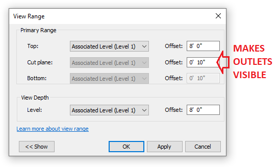
NOTE: IF YOUR CEILINGS ARE NOT 8′,
MAKE THE VIEW RANGE AND VIEW DEPTH MATCH YOUR CEILING HEIGHT!
YOU NEED TO ACTUALLY SEE YOUR CEILING IN ORDER TO PLACE LIGHTS!
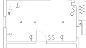
(Ignore the doors)
Switches and Outlets
We set the View Depth really low, so your outlets should show up. FIND your components from the INSERT menu and LOAD AUTODESK FAMILY.
Use the Place Component command. Switches and Outlets use walls as their host; you can only attach them to walls.
- Lights for each room and hallways
- Exterior lights
- Switches for lights and attached with double curved (use spline) centrelines
- 3-way switches for hallways and stairways (top and bottom) as appropriate
- Outlets – 30″ from corner of room and every 12′ and every 6′ on counters
- 220 outlets for stove/oven and dryer (electric hot water is 220, gas hot water is 120)
- GFI outlet for bathroom and GFI/WP outlet for front and back exterior
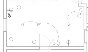
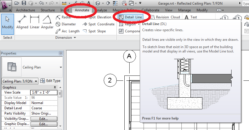
Wiring
From the [Annotate] tab of the Ribbon menu, select Detail Line, and draw arcs or splines to represent the wires from the switches to the light fixtures. You do not need to show the breaker panel, or wiring to the plugs. We just want to know which switches control which lights.
Adding to Floor Plan – Via Sheets
Create a SHEET (see: Annotating with RevIt) labeled FLOOR PLAN, and drag your floor plan onto it. Make sure the scale is set (usually 1/4″=1′)
Next, drag your CEILING PLAN (only electrical should be visible) onto the sheet, right on top of the Floor Plan. You should see some dashed reference lines show up when you are both Horizontally and Vertically aligned – it should snap into place. If the electrical scale is not also 1/4″=1′, correct it.