While this tutorial places ALL the views on one sheet, I want each floor to have its own sheet (unless your house is very small).
VIEW CROP REGIONS & SHEET PLACEMENT
Let’s place our drawing on a “sheet.”
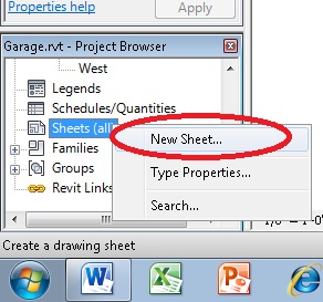
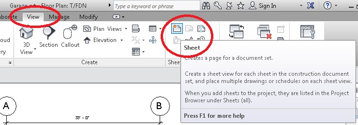
You can either RIGHT-CLICK a new sheet from your PROJECT BROWSER, or select VIEW and NEW SHEET
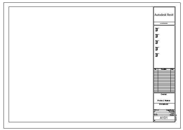
This will prompt you for a default Titleblock. While you can load a Titleblock from the Sheet Family, or create your own Titleblock, for now just accept the default.
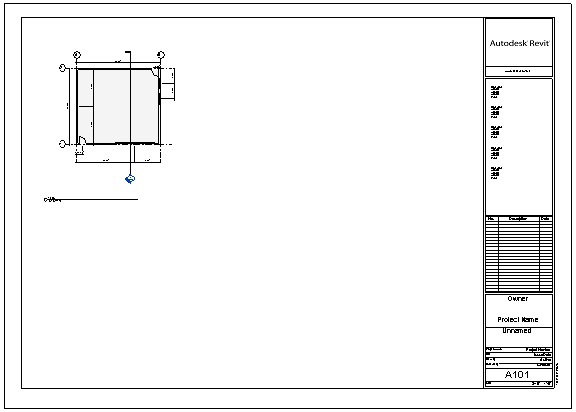
You should see this on the screen:
BUT, before we plunk our drawing in there, we need to change the Visibility of our Crop Region.
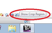
Go to the T/FDN view, and then at the bottom of the screen turn on “SHOW CROP REGION”
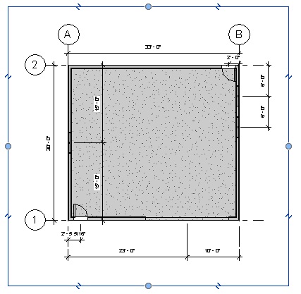
And then drag the crop region closer to the garage, like this:
Then TURN OFF the VISIBILITY and do the same for ALL THE VIEWS, cleaning up the extents of the various views. What you adjust the crop region to, is what you are going to see – so do a good job of it here or you may have issues later.
Check and adjust the crop region of the ELEVATION VIEWS as well. Ensure that HIDDEN LINE is on, NOT SHADED.
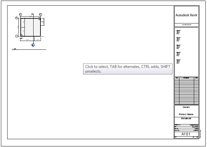
Now, go back to your A101 SHEET, then DRAG AND DROP the T/FDN Floor Plan right onto your sheet. It should look kind of like this:
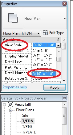
The SCALE is a bit small, so you can change that by going to the T/FDN FLOOR PLAN, going into the properties and changing the View Scale to 3/16″ = 1′-0″
Go back to the A101 Sheet, and the view should already be updated (you may need to adjust its placement):
If you have more than one view on the sheet, you can select ALL of your views (use CTRL to select multiple views), and change ALL of them to a scale that works.
While this tutorial places ALL the views on one sheet, I want each floor to have its own sheet (unless your house is very small).
-
-
- Floor Plan (each floor on its own sheet): 1/4″ = 1′-0″
- Elevation View: 3/16″=1′-0″ (or whatever fits the page nicely)
- Plot Plan: 3/16″=1′-0″ (or whatever fits the page nicely)
- 3D Views: Not To Scale (make them fit the page nicely)
- Section View: 3/16″=1′-0″
-
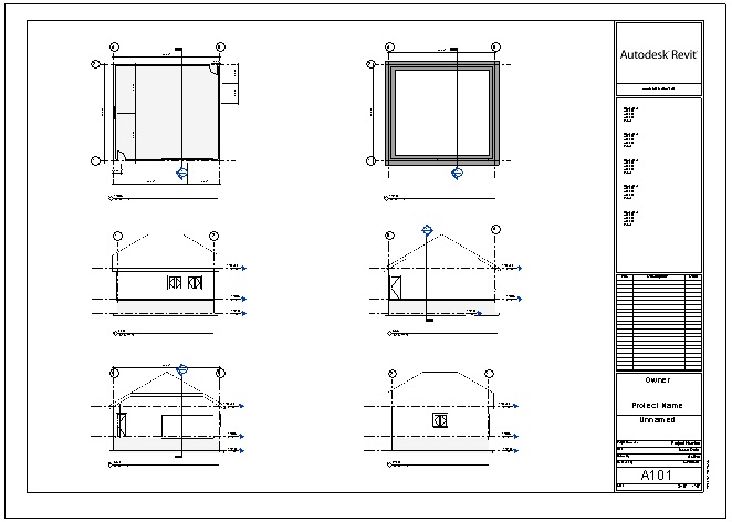
Add the other views (T/FTG, East, North, South, West) as well, nudging each view (with the arrow keys) until it looks pretty, like this (you can tweak the length and placement of the wee title strips, too):
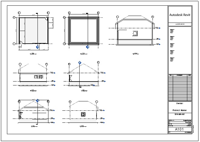
WAIT! We need to add a section view! Select all the views, and nudge them off to the left. Add the Section view (I also shortened the title strip lines):
ANNOTATE FLOOR PLAN
Now that we have all the views on our sheet, we are going to annotate the views. You will be adding dimensions and text.
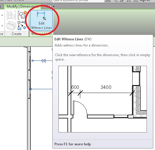
Make sure, as much as possible, your dimensions are OUTSIDE the drawing. You can add to existing dimensions by clicking on them, and then select EDIT WITNESS LINES, then clicking outside to finish.
Be sure to dimension to the outside edge of the wall plywood, NOT the exterior finish (hover over the edge you want, and tab-tab-tab… until it selects the edge you are after).
Set up your dimensions like this:
First Row:(closest to the building): Exterior Corners and edges to center of WINDOWS and DOORS
Second Row: Exterior Corners and edges to center of Interior WALLS (our Garage has no interior walls on the floor plan, so in this case, your third row will actually be the next row)
Third Row: Exterior Corners and edges (if any – our Garage has no “kick outs” on the floor plan, so in this case, your third row will actually be the next row)
Fourth Row: (furthest from the building): OVERALL Dimensions
Go ahead and annotate each floor plan as needed and as shown below. Make sure everything fits into the View Crop Region.
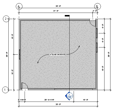
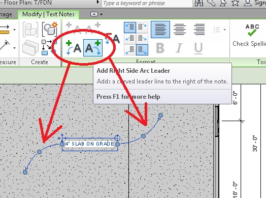
Use TEXT to annotate the concrete slab “4″ CONCRETE ON GRADE“, and use some ARC LEADERS to help detail the annotation. If you are building a wood frame house, you would indicate what the floor is constructed out of (according to local building code).