
Steam Engine Tutorial
Creating Parts Within An Assembly
In this tutorial, you will learn how to create an assembly of components AS YOU GO. This is a VERY GOOD way of creating, since you can REFERENCE existing parts (we’ll use PROJECT a lot), which LINK DIMENSIONS together (I’ll explain more about this as we get there).
This Steam Engine has eleven main parts to it. It is an actual project that my Level 2 Metalwork students often make.
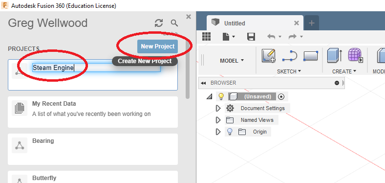
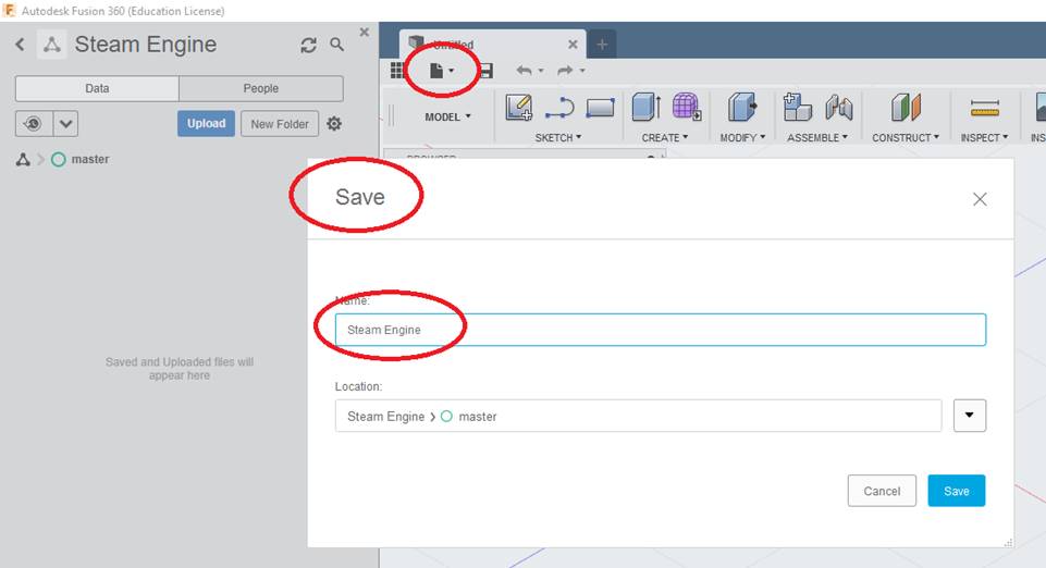
Let’s start by firing up Fusion360, and creating a new project:
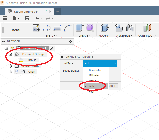
And change the UNITS to Inches:
From the ASSEMBLE tab on the RIBBON MENU, click NEW COMPONENT, and name it BODY. You will notice the cube that represents “Steam Engine” turns into an assembly, and “Body” appears below.
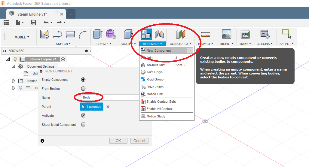
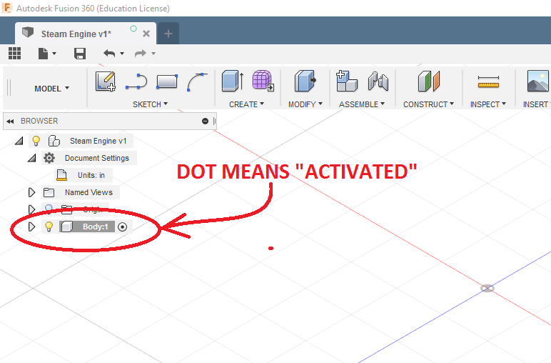
Notice also, that “BODY” is now ACTIVATED. You activate any part you create to work on it. When you want to create a NEW part, you MUST activate the original assembly (or weird things can happen).
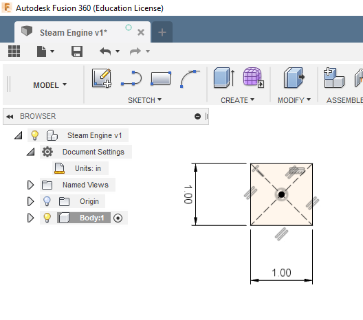
Now create this sketch (notice it is drawn using CENTER RECTANGLE right on the ORIGIN – this keeps work planes in the exact middle, which will make things a LOT easier later. This is part of PLANNING AHEAD:
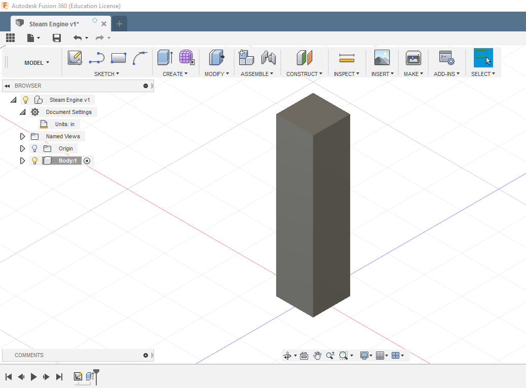
And extrude it to a height of 4.25 inches
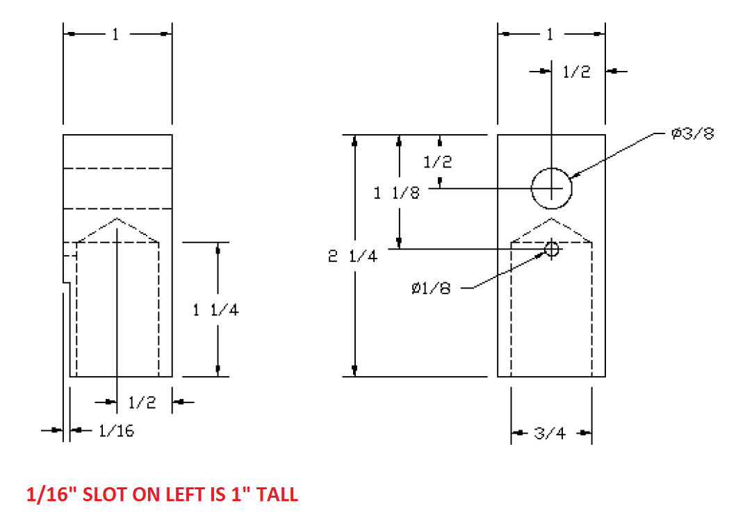
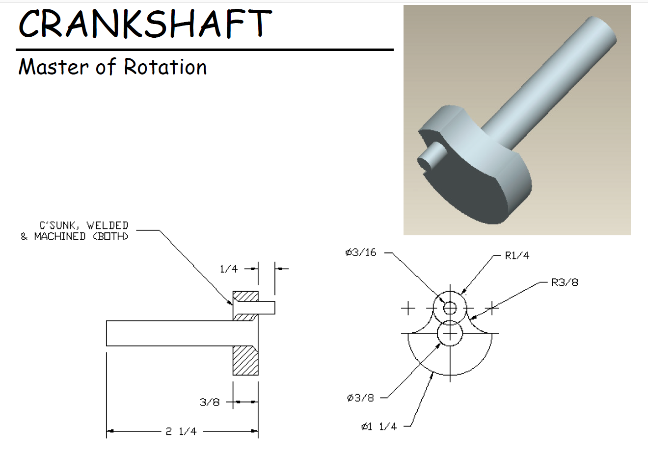
Following this diagram, add the two grooves, the two steam holes (one goes through, one turns half-way through), the crankshaft hole, and the blind hole at the top. Use PROJECT to find the edges of things to help with the 3/8″ wide slots. That’s a threaded hole in the bottom:
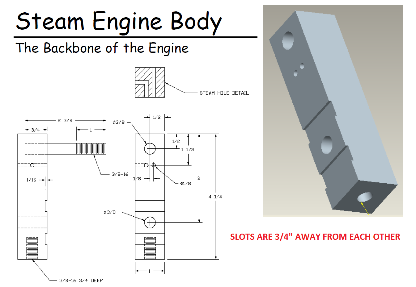
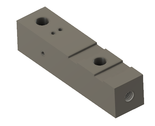
You should now have this:
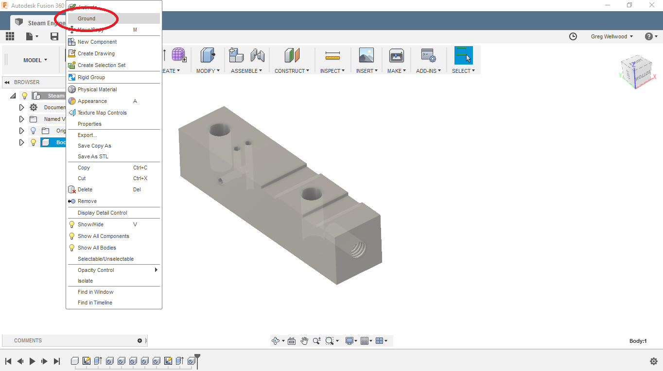
Right-Click on the Body you just made, and GROUND it. This anchors the part into reality, so all other parts can be built off it. Something needs to be FIXED (immobile), and GROUNDING fixes it. You should see a RED THUMBTACK show up in the browser at the Body component.
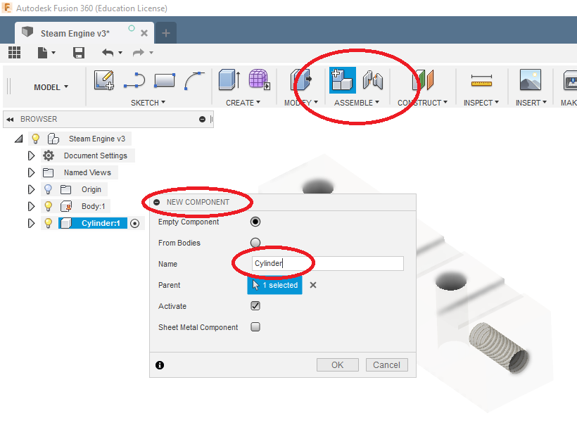
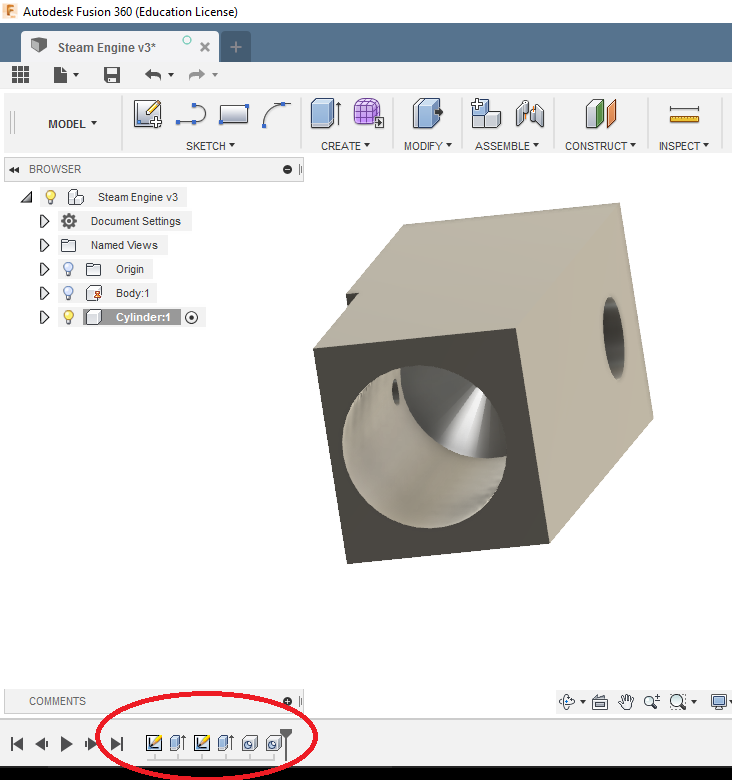
Now go to the top of the BROWSER and ACTIVATE the assembly, if it isn’t already. Then go to ASSEMBLE on the Ribbon Menu and pick NEW COMPONENT and name it CYLINDER. While you can chose a different PARENT for each part, for this simple assembly we’re just keep the Assembly itself the parent. You will notice, with the addition of a new part, the other parts will “gray out” so as to be less visible – this can be handy later.
Here is where it’s going to get tricky.
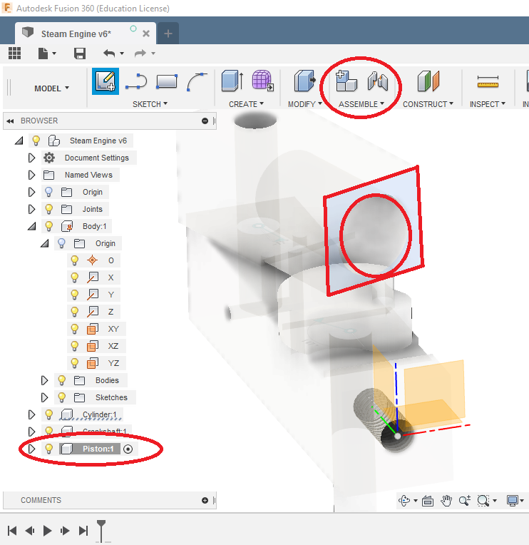
Create a SKETCH on the front surface of the BODY where the cylinder is going to go (you may have to rotate around a bit to get Fusion to click the surface, since it’s grayed out). Once you are in the sketcher, PROJECT the geometry of the upper hole of the BODY – we want to REFERENCE that hole to create the CYLINDER.
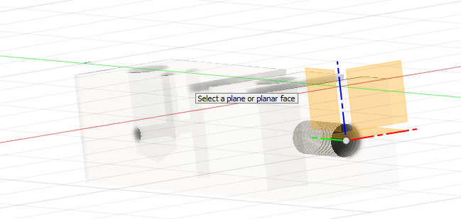
In SKETCH, use PROJECT and click on the grayed surface of the BODY. We’re going to draw to match that. Create the shape as shown below.
Handy Tip: Turn off the LIGHTBULB to the BODY to get inside for the 1/8″ Hole. This “hides” the Body entirely.
Drill the 1/8″ hole TO the INSIDE of the 3/4″ hole (no need to measure).
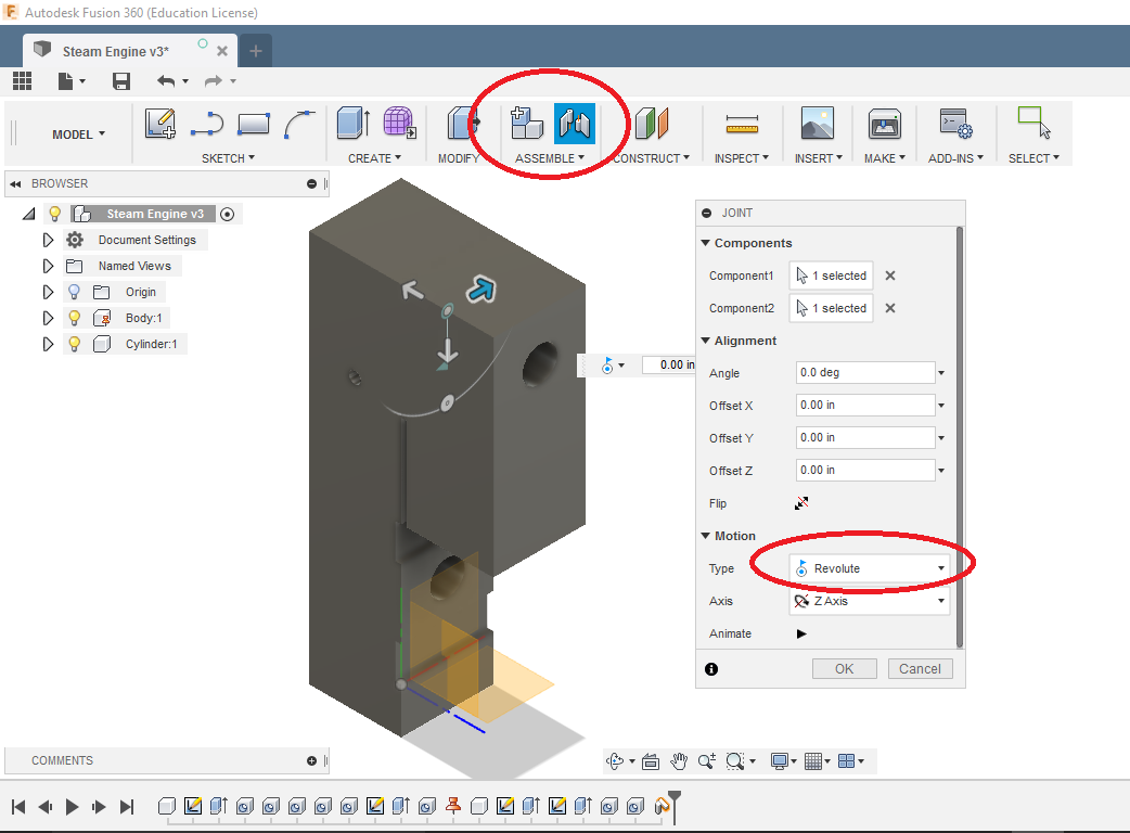
Go back and ACTIVATE the ASSEMBLY, then click and drag the CYLINDER. It will move. Use JOIN in the ASSEMBLE tab of the Ribbon Menu to JOIN the CYLINDER to the BODY where the FACES MATE and the HOLES are REVOLUTE. I picked JOINTS of the outside of the Body Hole, and the Inside of the Cylinder Hole. You will find Fusion conveniently grays out components you can’t join to.
You should be able to click and spin the CYLINDER around the “hole” of the BODY.
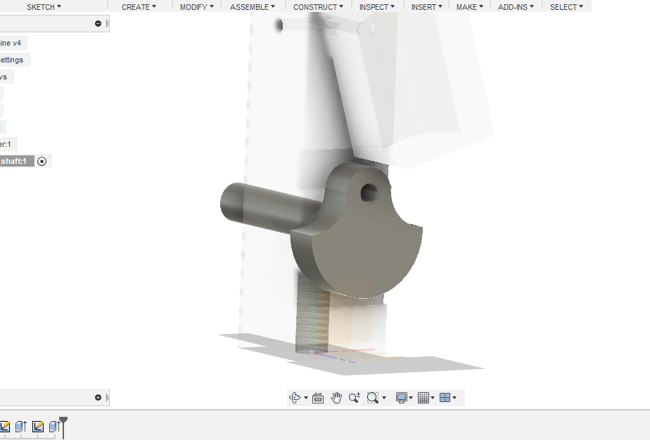
Create a NEW COMPONENT called CRANKSHAFT, and start its sketch on the near side of the CRANKSHAFT HOLE of the BODY, beneath the CYLINDER.
We’ll start by PROJECTING the hole so you don’t have to measure it. Then do a TWO-SIDE EXTRUDE of a circle, extruding 1 7/8″ into the BODY (it will poke out the other side), and 3/8″ out of the body (to hold the COUNTERWEIGHT).
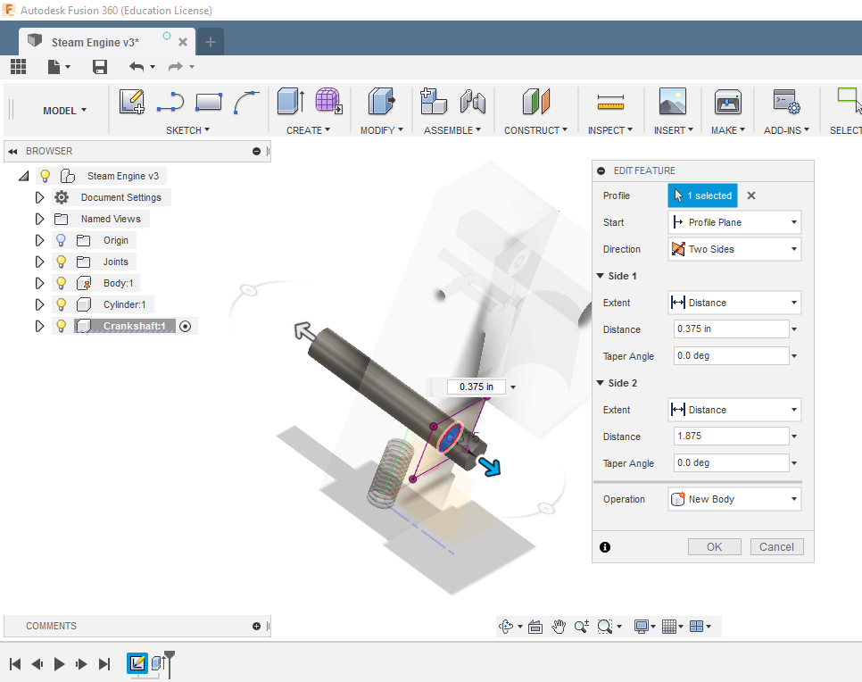
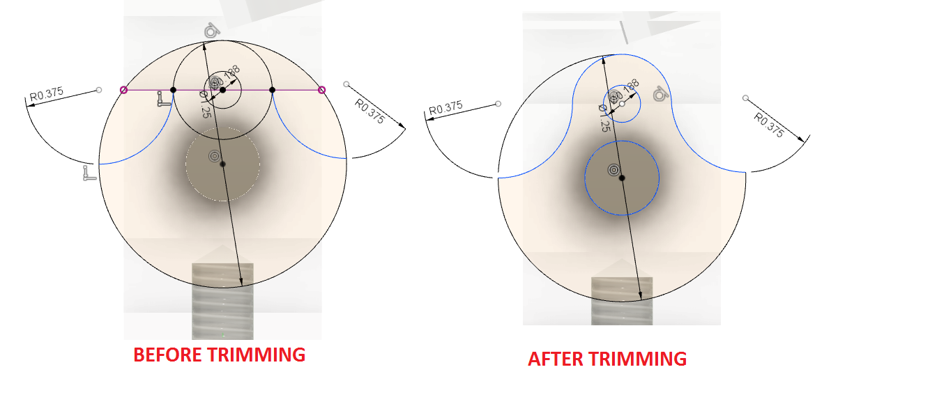
The COUNTERWEIGHT can have its sketch off the end of the extruded shaft, or off the BODY. I’m not sure it matters. Though, the surface you use will require a different extrude direction. You’ll know when you get there.
If you have not saved your working, you crazy gambler, you should probably save now.
Now make the CRANKSHAFT be REVOLUTE, with the backside of the COUNTERWEIGHT flush with the front-side of the BODY (try selecting the EDGE of the Counterweight-to-Crankshaft connection, and the EDGE of the crankshaft hole in the body) . Do a Front-side Ollie to celebrate.
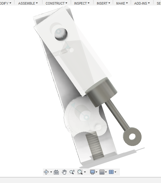
We’re going to make the Piston next.
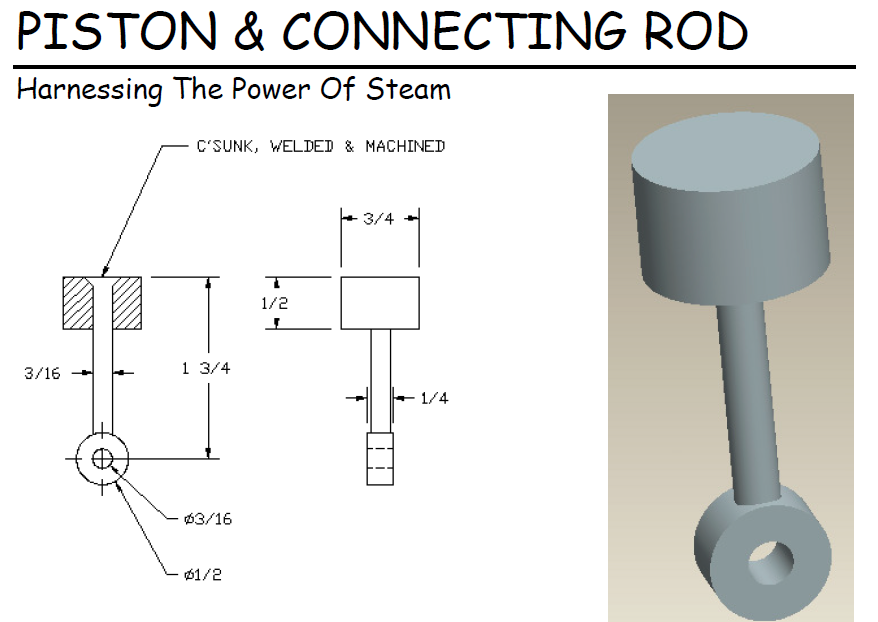
ACTIVATE the assembly again, and create a NEW COMPONENT, sketching on the BOTTOM of the cylinder so we can PROJECT (and thus, reference) the hole.
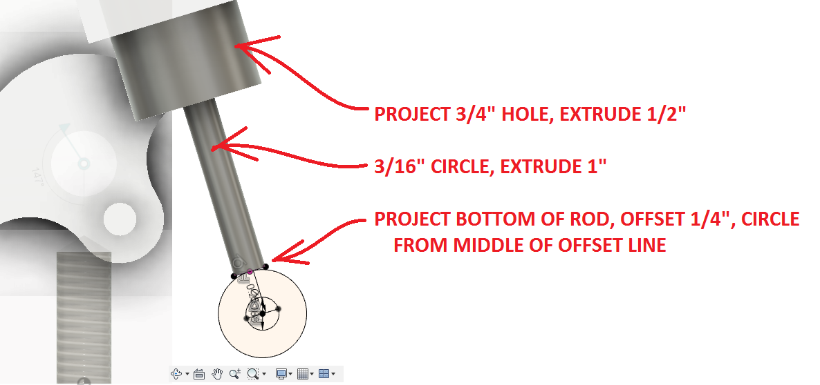
Now you need to JOINT the PISTON into the CYLINDER, make it a SLIDER.
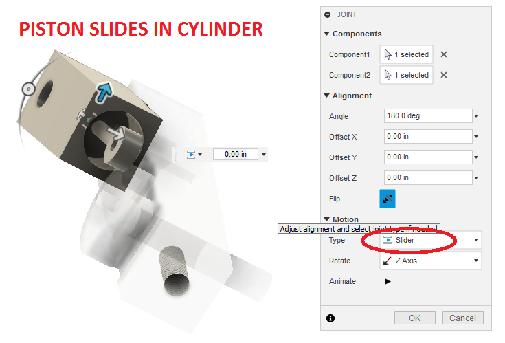
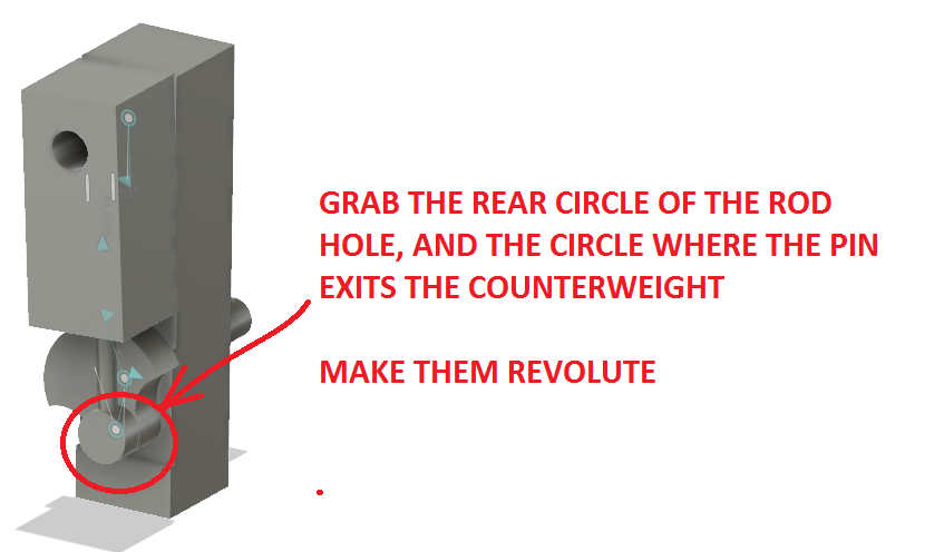
Then JOINT the bottom of the Rod to the Crank Pin (If Revolute is drunk, try Cylinder).
You should be able to rotate the crankshaft now, and have the piston go up and down the now rocking cylinder. Rockin!
Fusion360 can automatically rotate the crankshaft so as to have it rotating in a video – find Animate Joint.
Let’s make a FLYWHEEL!
Oh yeah – ACTIVATE the Assembly, NEW COMPONENT, Give’r!
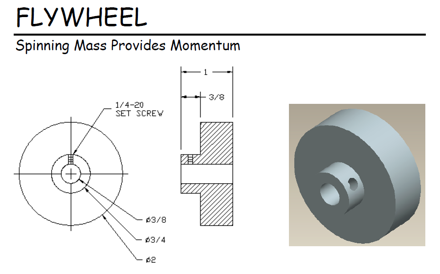
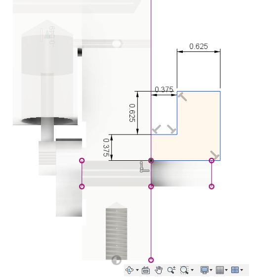
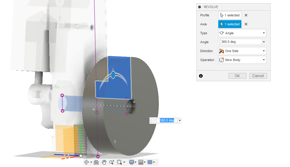
RIGID Joint on the end of the CRANKSHAFT. You could do two EXTRUDES, or you could do one REVOLVE. Which one do you think would be FASTER? I did a REVOLVE, picking the XY ORIGIN PLANE as my sketching plane, and PROJECTING the CRANKSHAFT so I don’t have to measure! Pick the center of the CRANKSHAFT for the revolve axis.
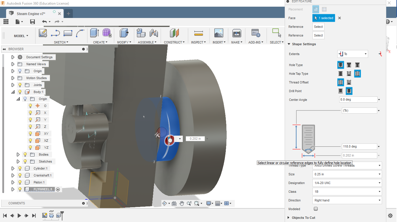
Do a 1/4″-20 (UNC) threaded hole for the setscrew to attach the FLYWHEEL.
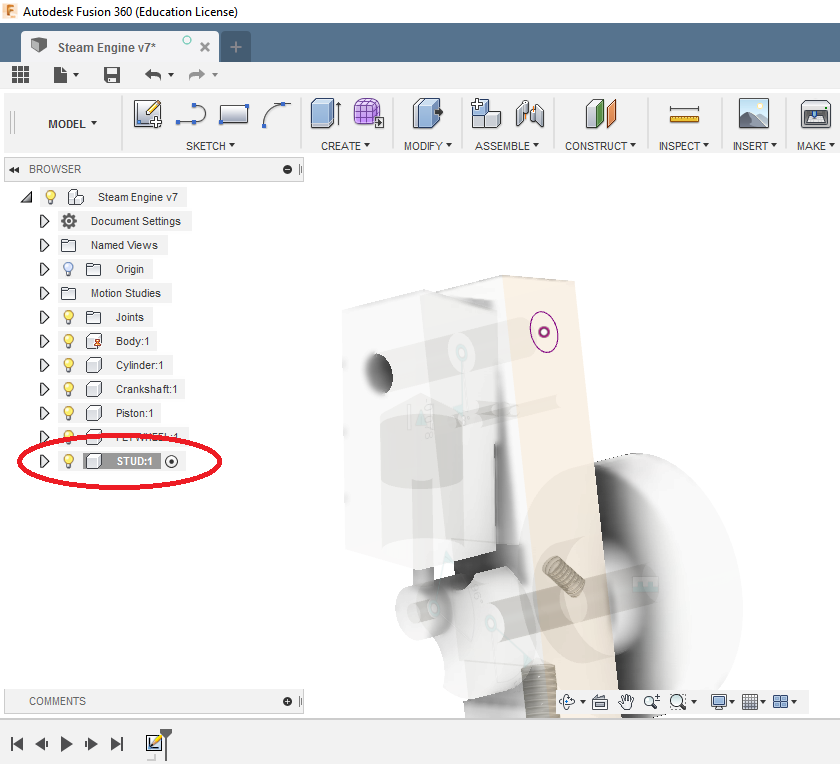
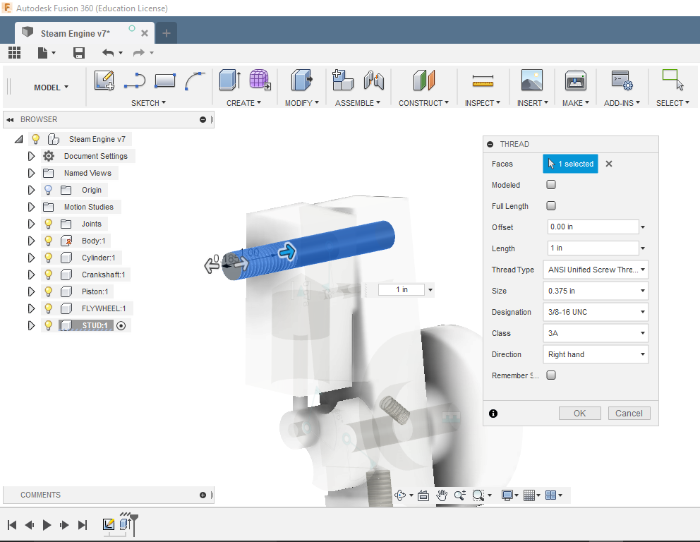
It looks like I forgot to make the STUD. Let’s do that. ACTIVATE the Assembly, NEW COMPONENT, and PROJECT the TOP HOLE of the BODY, and sketch a circle the same size as the hole (no need to measure). Extrude 2-3/4″, and thread the end 1″ with 3/8-16 (UNC) threads – look in CREATE for THREADS.
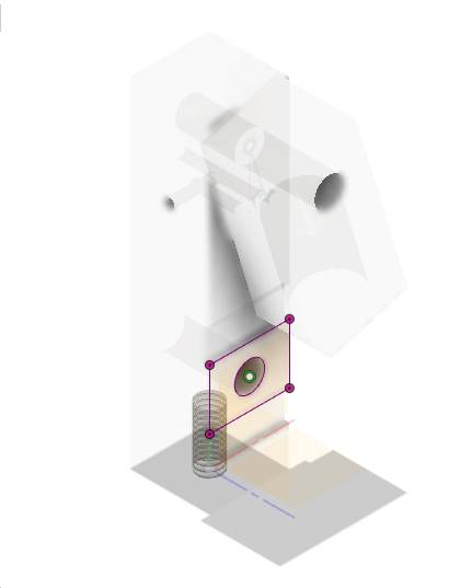
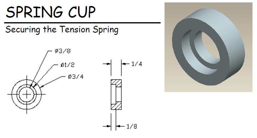
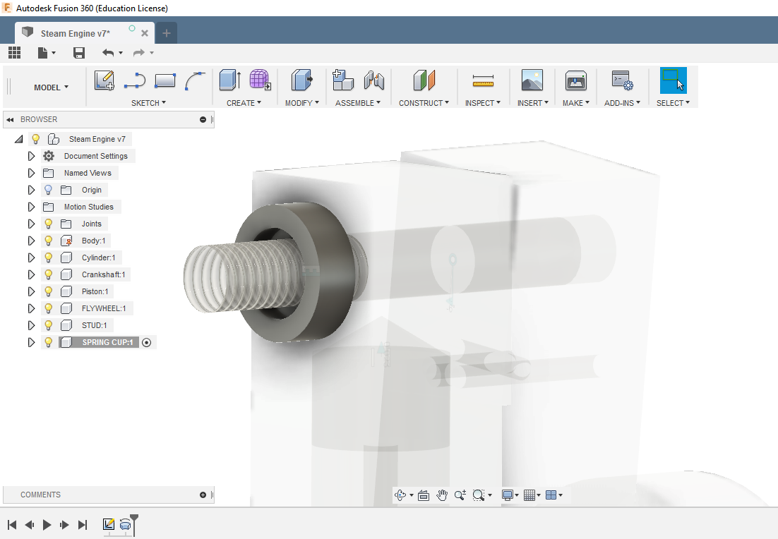
SPRING CUP is next. How would you make this one in the fastest way? Keep using PROJECT – it makes life easier.
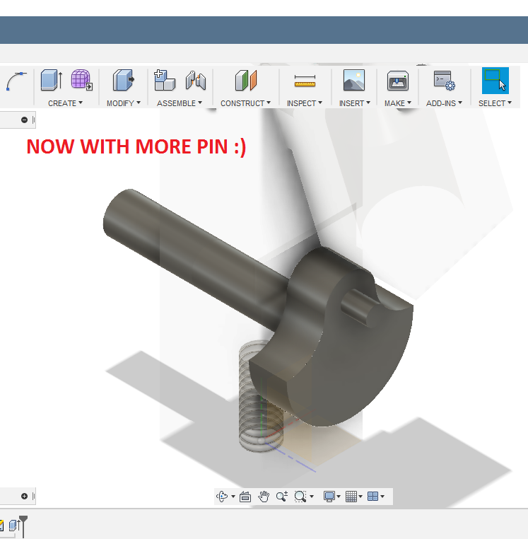
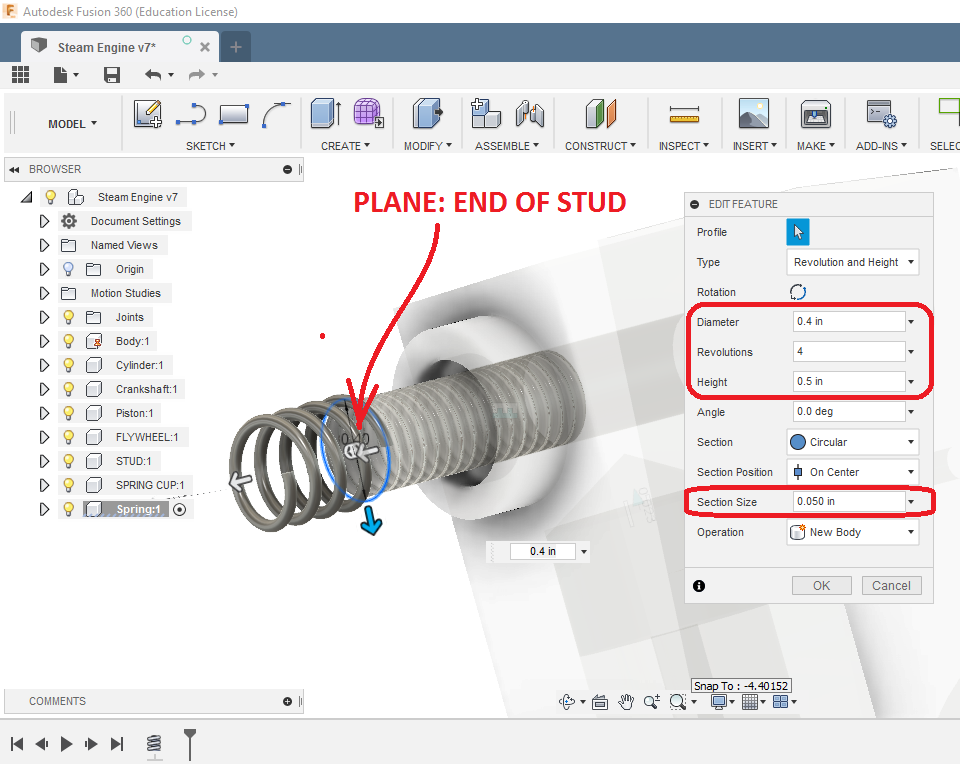
The SPRING is made by CREATE a COIL. First, oh yes, ACTIVATE, and NEW COMPONENT.
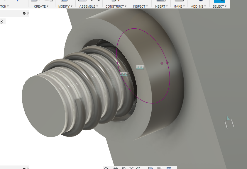
To JOINT the spring, I needed to add a SKETCH of a CIRCLE to the SPRING, since I could not actually JOIN the SPRING.
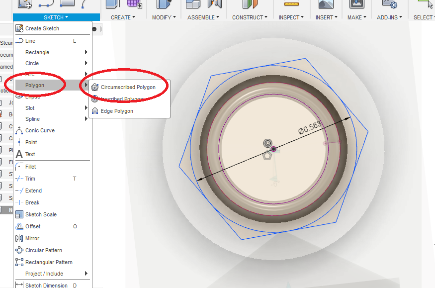
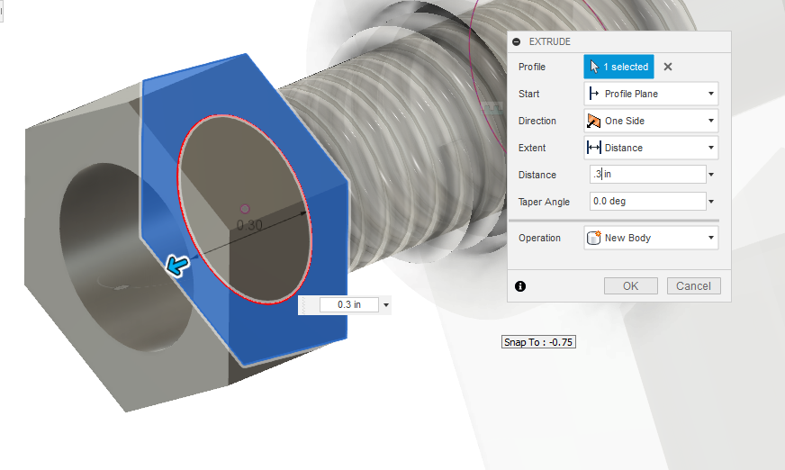
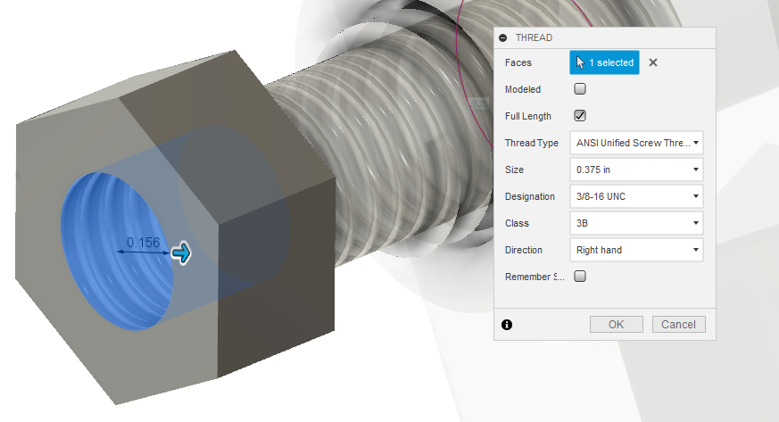
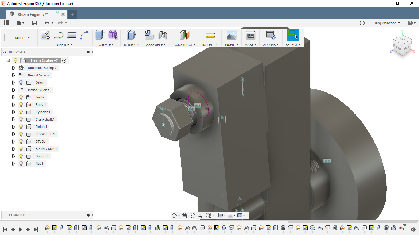
Next is the NUT. ACTIVATE. NEW COMPONENT. PROJECT. Sketch a HEX (360° divided by 6 sides!), THREAD the inside 3/8-16 UNC. I think the SPRING is too long, I’m going to shorten it to 1/4″ and 3 coils. NOTE: a 3/8″ nut has a 9/16″ hex on it.
Oh. My. Gosh.
CREATE a 1/4″-20 set screw to attach the flywheel to the crankshaft.
CREATE a sweet Rendered View of the Steam Engine (see below for an example)
CREATE an animated exploded view of the Steam Engine (bonus if you can make the nut and set screw “un-thread”). (Does THIS help you??) See Level 1 Tutorial 9!
CREATE a set of Drawings of the steam engine that are better than mine (grin) See Level 1 Tutorial 8!

Have your Instructor mark this on the screen.
Now complete Tutorial 2