Body Chassis Drivetrain |
Electrical Interior MegaSquirt |
First Drive Racing Media Daily Driving |
Suspension is hard to do on the cheap. I initially cheaped out and tried to make my own coilovers, fabricating non-adjustable sleeves and spring perches. I tried to make it all work with coil springs of dubious origin. This cost about $160 for materials, springs and shocks. This pleased me, as the “right” parts will set you back about $1000CDN. I’ve since made enough changes that I broke down and ordered AFCO sleeve kits ($180US), and proper size/rate 1-7/8″ ($180) springs, and I’m sure it’s not over yet.
The next one will be much better….
Design
I chose my desired ride and roll centre heights first.
I chose a race height of 4″ (chassis to ground), as I felt this was the reasonable minimum for the car in competition with 20″ tall slicks. With 22.7″ street tires, ground clearance will increase to clear pesky speed bumps and low-flying birds.
I chose roll centres at 2″ front (turned out to be WAY too tall), and 4″ rear. Unfortunately, “The Book” rear roll centre would be at 10″ race height; too high (in my opinion). To counter this I mounted a panhard rod below the rear section of the frame, with a notch cut for bump travel (which had to be enlarged for more bump travel). I made one end adjustable so I could tune in more oversteer if I need to.
Testing showed that I needed a lower front roll center (it’s currently 0.875″), plus front and rear sway bars. The adjustable panhard provided marginally effective changes.
Designing around the roll center
Wishbones and Uprights – Part I
I used cut struts for uprights and a 3/4″ rod end (a bit on the large side) as an upper joint. Rod ends don’t like large angles, so I designed the upper arms to sit 90° to the strut housing at ride height. This won’t give me an optimal camber curve, but the joint will survive it’s life within it’s limits of angularity. Next time…..
The Corolla struts are shortened to 3.5″ above the hub casting to use as uprights. A 3/4″ grade 8 bolt attaches the upper joint to the strut through a welded, threaded cap. A-arms are 1″ .090 DOM steel. Much stronger than “the Book’s” 3/4″ .063 DOM. The upper arm is curved for spring clearance.
Upper ball joint is Aurora MM-12T, $60 each (2004). Good for 11,000psi. I’m not an engineer – I hope it works. A small spacer is mounted under the upper rod end to increase angularity of the joint. If I were to do this again, I would use a 5/8″ or 1/2″ rod end, if I didn’t make or purchase different uprights.
Lower balljoints are Chevette – they fit the Corolla uprights when installed with a washer under the nut.
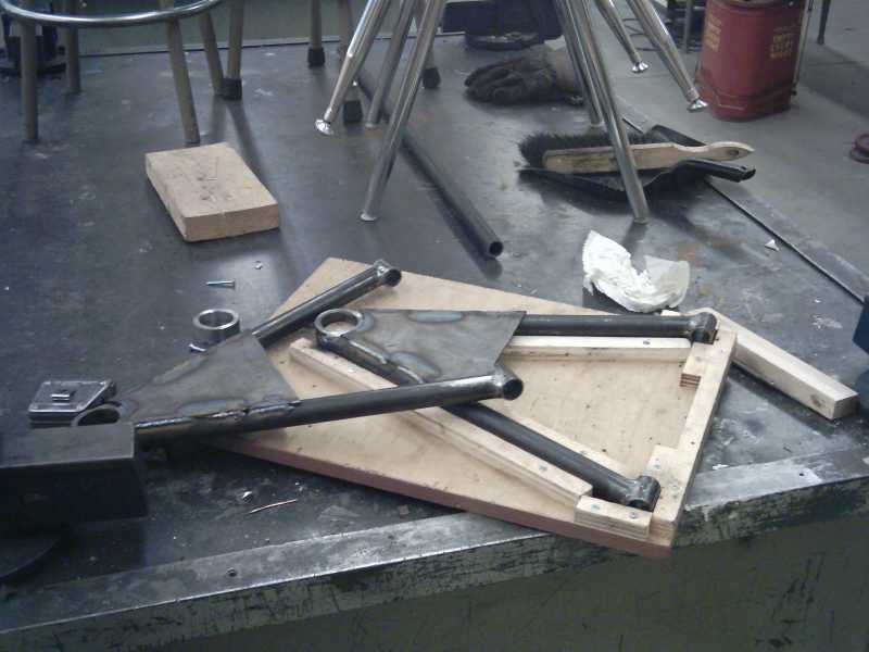
Control arm jig
Shortened strut, capped, 3/4″ rod end
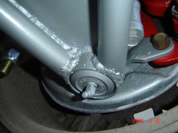
Pressed-in Chevette lower joint
Home-made spring mounts (later discarded in favour of AFCO sleeves)
Wishbones and Uprights – Part II
Apparently shortening MacStruts, capping them and adding a spherical rod end is frowned upon.
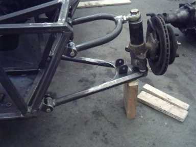
I am now using 1984 Chevette spindles (they have larger brakes), with Datsun 210 hubs and rotors (essentially bolt-on, with merely Datsun B210 seal) to give me 4×114.3mm bolt pattern (and replaceable rotors – the Chevettes are one piece with the hub).
The upper control arms were re-fabricated, and instead of using a rod end, a Moog ES422R was fitted as an upper ball joint. Since the track is wider than the Chevette, Moog ES2261 tie rod ends are a bit longer to lengthen the rack.
This fabrication changes the ride height and roll centre – but through careful study over one winter, decided the tiny improvement was not worth the colossal change required. A lower front ride height turned out to be a good thing (see above).
Using Chevette spindles also changes the steering to front steer, whereas the Corolla was rear steer. Not insurmountable, but another annoyance nonetheless.
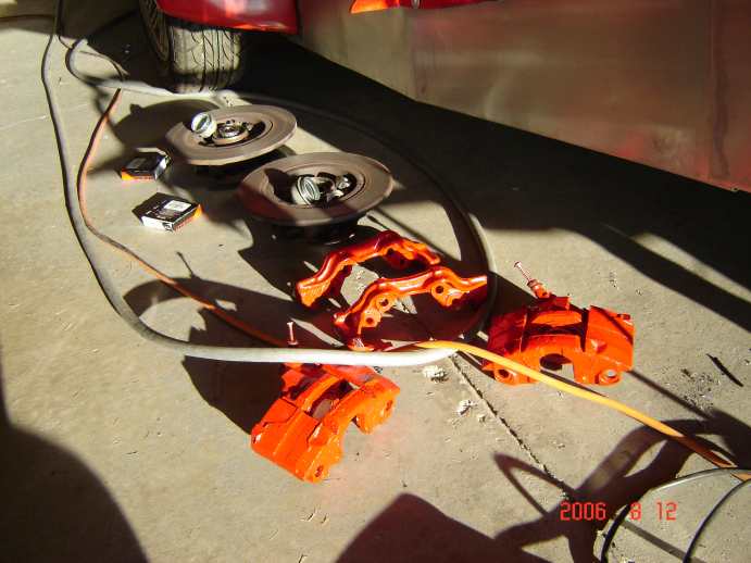
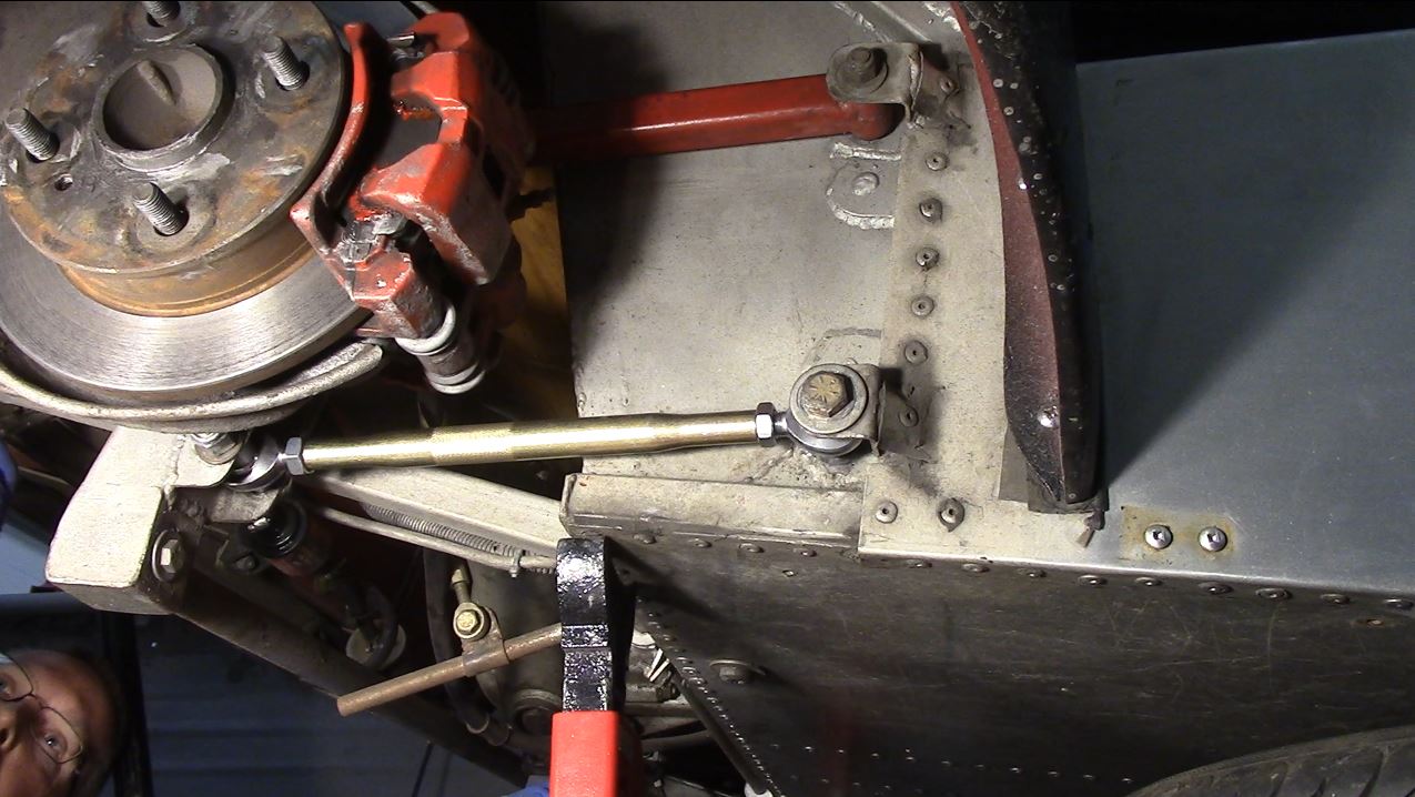
Chevette spindles and calipers, Datsun 210 hubs and rotors, Datsun B210 dust seal
IF I WERE TO DO THIS AGAIN…
I would angle the upper control arm LESS (lower roll center), but make it SHORTER (better camber curve). As it turned out, I had to lower the front considerably in order to get the front to grip – A lower roll center would have been better to start with. I’d shoot for around ground level front roll center. Rear of 4″ is still good.
Trailing Arms and Panhard
The rear trailing arms were originally set up as per “The Book,” but they got in the way of the Corolla disc brake calipers. I pulled the axles as swapped the brakes to the rear (left-for-right). Then the e-Brake cable got in the way of the shocks. SO I re-made the axle mount with the trailing arms 3″ further away than the plans called for and put the brakes back where they came from.
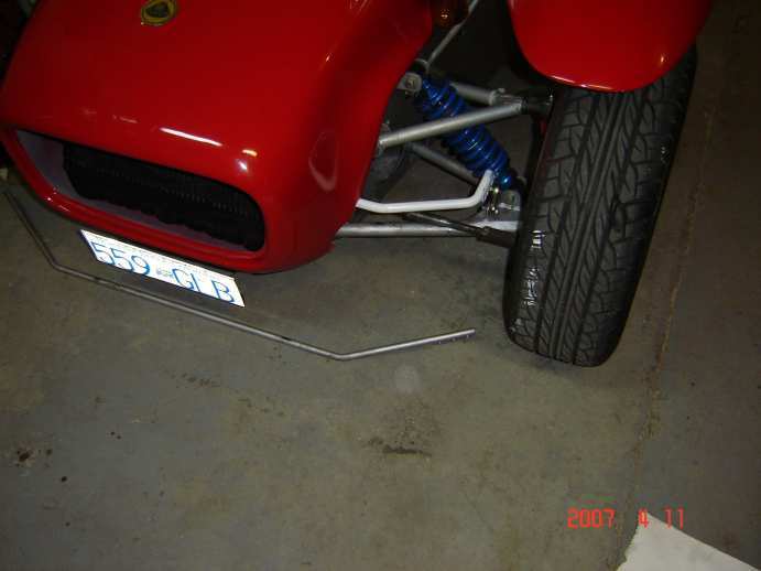
The panhard rod was located below the frame, with a kickout to allow more bump travel. The panhard is set for 4″ rear roll centre, as opposed to The Book’s 10″ height (on slicks). I have found only one other person doing the same thing, and many complaining of a Book Locost’s propensity to oversteer.
The lower panhard bar did in fact make the car very predictable to drive – this modification to the “book” design was a very good one.
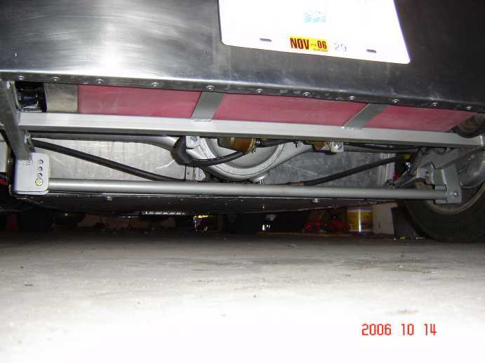
Panhard mounted under the frame for a lower rear roll center
Bushings
All bushings were UHMW Polyethylene. While this worked fine in the front, the rear trailing arms required more compliance, and UHMWPE couldn’t give that. The back was very easy (and predictable) to slide out – I attribute this to the bushings.
I installed a set of Triumph Spitfire rubber bushings which were installed on the rear. Much cheaper than a full set of spherical rod ends ($25 vs. $250+), and made a SIGNIFICANT improvement on both ride quality and control.
The lower trailing arm leading bushing remained UHMWPE, as it shared the seat belt bolt, and did not have a sleeve inside – this was replaced in 2021 (see below).
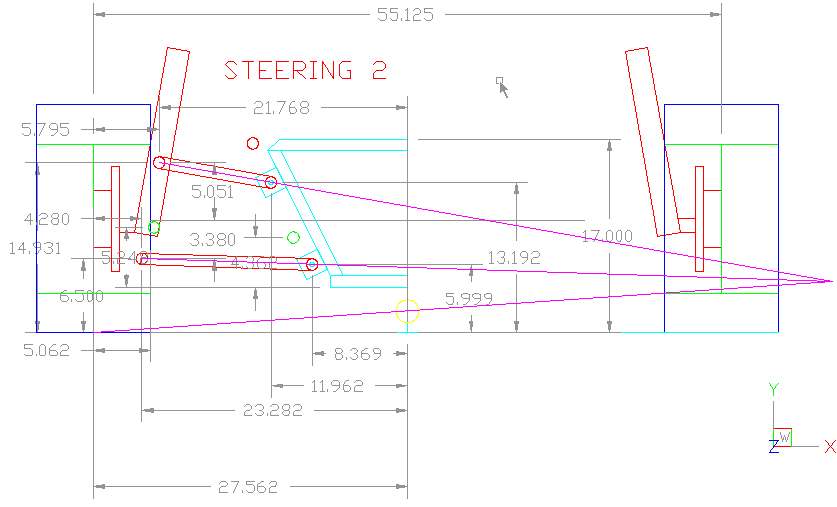
Steering – Part I
The steering column had been stripped of its tilt option, and had been shortened to fit under the scuttle, while the steering shaft itself had been lengthened to meet the rack. This is not what I now have.
Once the front arms were installed, the Corolla rack and pinion was shortened 3.5″ and converted to manual steer. It was be mounted 3.5″ above the bottom of the frame to reduce bump steer. I used a Basic program called “Wishbone,” Then switched to “Susprog3D” to design the suspension and steering. I was able to reduce bump steer to .003″ toe out within the full range of suspension travel. This is not what I now have.
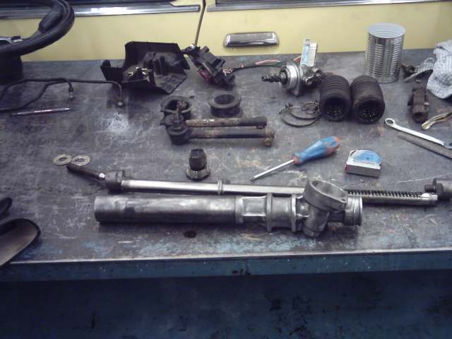
Unsassembled Corolla GT-S power steering rack
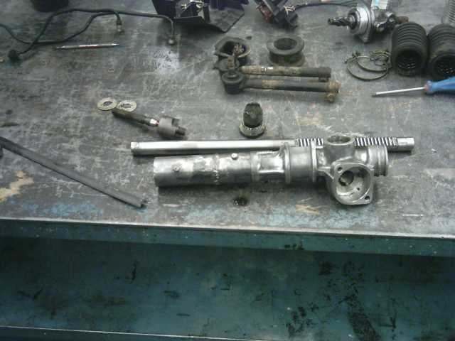
Shortened 3.5″
Steering – Part II Sept 2006
Apparently shortening and de-powering a steering rack, and lengthening a steering shaft is frowned upon.
When I changed to Chevette spindles, I also installed a Chevette rack which was almost long enough to reach the spindles, but a little too long to reduce bumpsteer.
Having driven the car with this non-optimal rack width, I did not “feel” any bumpsteer, but the steering never really felt 100% confident. I know there is some, as I can see it, but I do not feel it on the street.
Later B-series Mazda pickups have a universal joint that matches the Chevette splines. The trick is then finding a combination of steering shafts that will work, as you are not allowed to weld anything. I spent two full days at Pick-n-Pull and I don’t know what all I got that ended up working. I took parts from a LOT of vehicles.
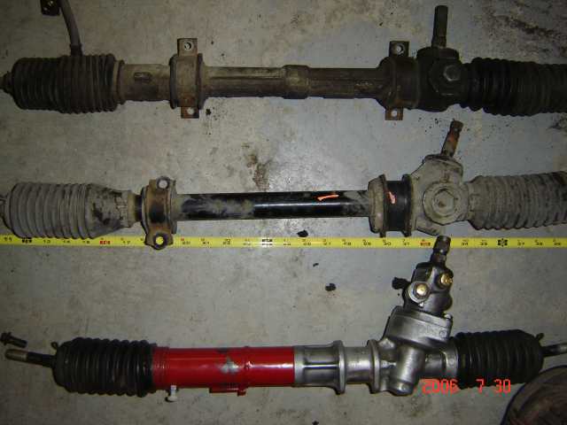
Top to bottom: Chevette, Tercel, Corolla
Steering – Part III May 2007
I also found that the Chevette rack is really slow: 4 turns lock-to-lock. I bought an MG Midget rack (Late Triumph design) on eBay for $15 Which was 3 turns lock-to-lock. I also spent a couple days over Christmas working through the front end geometry only to find any changes I could make would be very large, with the resulting improvement very small. I left it as is, but did optimize the steering rack by shortening it 7-1/2″. Tie rod end adapters were fabricated to connect the MG tie rod ends to the Chevette tie rods.
The resulting steering feels significantly better! It’s faster, and I feels much more “at one” while driving.
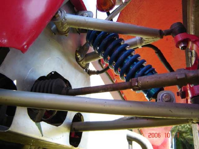
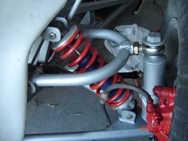
Springs and Shocks – Part I
Following Steve Smith’s “Dwarf Car Technology,” I used mid-70’s Chevy Nova front shocks for the front. Steve’s recommendation for rear shocks wouldn’t fit (mid-80’s Blazer “Quad-Shock”), so I took a page from the Triumph Spitfire guys and bought mid-70’s Chevy Corvette rear shocks. These were WAY too stiff for the rear springs, so I swapped them with the fronts.
I am running 320lb springs on the front, with 140lb springs on the rear, chosen by calculation and a chosen low 2cps suspension frequency. They “appear” reasonably matched to the shocks (though there is a LOT of rebound damping), but the rear shocks (Nova) are a too stiff. I can always buy AFCO shocks at $85 each….. (sigh)
To mount these shocks in the Locost, the top mount of the Nova shocks need to be changed. They come as a stud instead of an eye. If you mount this shock like a true S2 is done (a stud through the top plate), there is no problem. This, however, gets in the way of a welded roll bar. I cut the stud off, and welded on a section of 1″ .090 DOM tube left over from the suspension. I made a few extra bushings and inserted them and bam, there you go.
IF I WERE TO DO IT AGAIN…
I would leave the stud on the rear shocks, and mount them as per a real 7. Then make a bolt-on roll bar, the mounting flange and tube of which would surround the shock stud.
To fit the AFCO sleeves, I welded a 1/8″ thick ring to the bottom of each shock – taking my time so they wouldn’t explode. Then I chucked them in the lathe and machined them perfectly straight and down in diameter to fit the sleeves. These rear shocks are not what I now have.
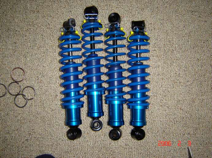
Monroe cheapie shocks, AFCO sleeve kit, SSS springs
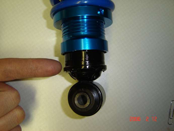
Welded ring to secure sleeves (careful!)
Springs and Shocks – Part II May 2007
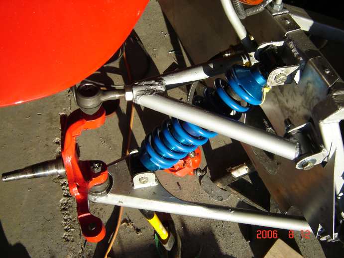
At the same time that I installed the MG Midget rack, in an effort to control oversteer, I fabricated a 1/2″ front sway bar. Assuming that the suspension wouldn’t move much, and assuming the steel would remain within it’s elasticity range, I fabricated the bar out of 1/2″ Cold Rold Mild Steel (CRMS). An inadequate improvement. The sway bar mounts attached to the diagonal “Aussie Tubes” at the front of the frame using some polyurethane bushings I had from the Sentra.
The next bar I made was 5/8″ CRMS, with better bends to make adjustments easier, and to look better. This bar really dialed the car in, and I stopped spinning the car every event (much to the disappointment of the local photographers). I found out later that this was mainly due to my NOT running a limited slip differential – required in this car!!
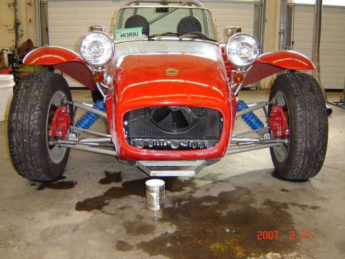
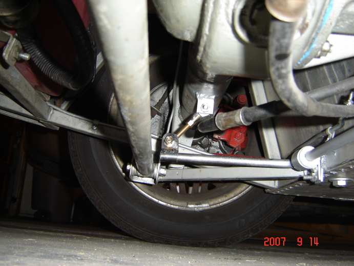
MG rack, with 1/2″ sway bar
5/8″ bar (white) with badly designed 1/2″ bar on floor
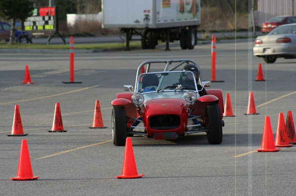
Sway bar seems to be working well – but check out that tire flex! Yuck!
Springs and Shocks – Part III September 2007
Once I got used to the bar, and to running slicks, I found the car really understeered. I tried everything from radical ride heights, outlandish alignment settings, to removing the bar once again (now that an LSD was putting power down – see Drivetrain).
I also found while installing the LSD, that one of my rear shocks was pooched. In an effort to soften the rear shocks, I mounted them upside down. Monroe said not to do this as the damping would be greatly reduced – which was exactly what I wanted! Unfortunately within a few thousand kilometers, the gas charge ended up where the oil was supposed to be and the oil ended up where the gas was supposed to be, and the seal leaked all the oil out.
So I poured over the shock catalogues again, and picked rear shocks for an ’85 Chevrolet Sprint. These are double-eye, so all I had to do was weld a perch for the spring sleeve (I used tubing this time, to raise the perch), grind off the dust sleeve and mount to the car.
I also found that I did not have enough bump travel. The book calls for 2″ bump travel, but the axle was moving more than that, and hitting the chassis before the shocks bottomed. I also had made the tranny tunnel too narrow and too short. I relocated a couple tubes for more travel and it’s much MUCH better now. I now have about 3-1/2″ bump travel. The shocks are beautifully balanced with the 140# springs.
I also spent some time learning more about sway bars and discovered that I had way too much front bar. Removing the bar made the car easier to drive with better turn-in, but it still didn’t feel “right.” I fabricated a rear sway bar out of 1/2″ CRS, but has not been tested as yet. I also came to the conclusion that I have some brake bias issues that will require complete re-designing of the pedal assembly. More to come on that one.
New rear 1/2″ sway bar
UPDATE JUNE 2021
Lower trailing arms were replaced with spherical rod ends. A bit more pricey, but by now the car has been on the road for 15 years and could use some love. The rod ends allowed better compliance in the suspension, and allowed me to finally fully tighten the seat belt bolt (gasp!). Just for giggles, the low pressure fuel pump cacked during the swap, for no reason other than to be annoying.
Depending if this produces any improvement, I may replace all the others are well.