This Tutorial is Adapted from CADclips Double Car Garage (YouTube)
Students can download a FREE and LEGAL copy of REVIT HERE
[Template] [Grid-Lines] [Levels/Layers] [Walls/Wall-Types] [Roof] [Foundation] [Footings] [Constraints] [Windows/Doors] [Lowering-Doors] [Floors/Slabs]
Start up RevIt Architecture – it should already be installed on the School Computers.

From the DROP-DOWN menu, select NEW and then PROJECT
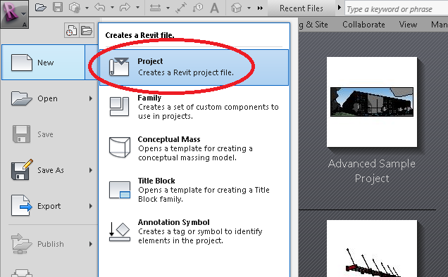
Select the DEFAULT.RTE template <<< Important!!
(you might need to BROWSE to find it)

This will open a new TEMPLATE, starting with Level 1. Use your MIDDLE MOUSE BUTTON to PAN (by holding and dragging) and ZOOM (scrolling the wheel)
We are going to set up some dimensions for our garage to be. We want to build a double-car garage, about 24′ by 26′
NOTE! YOU MAY NEED TO “HUNT” FOR THE TEMPLATE IF YOU’RE WORKING FROM HOME:
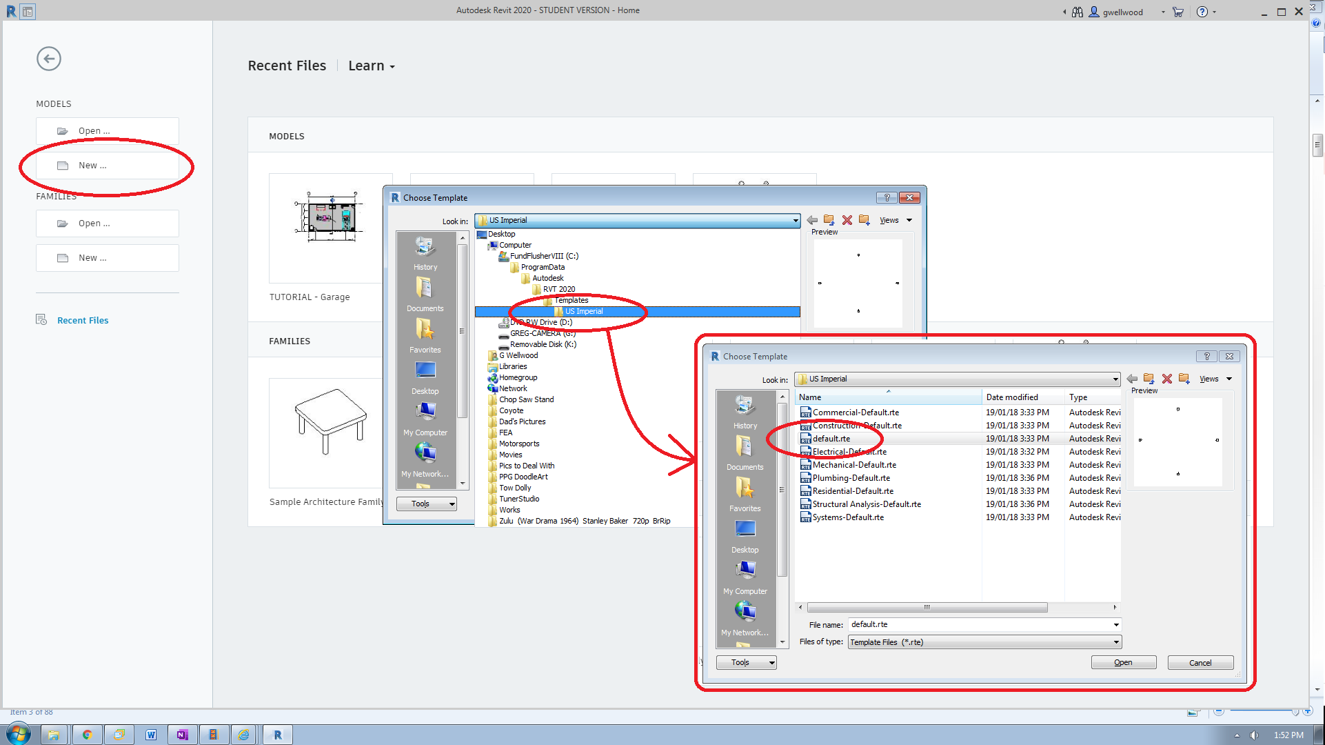
RevIt does NOT save your work in “Neverneverland” – YOU have to save it.
MAKE SURE YOU SAVE IT TO YOUR DOCUMENTS FOLDER
AND THEN CHECK THAT IT’S ACTUALLY THERE!
The Revit Desktop should look like this:
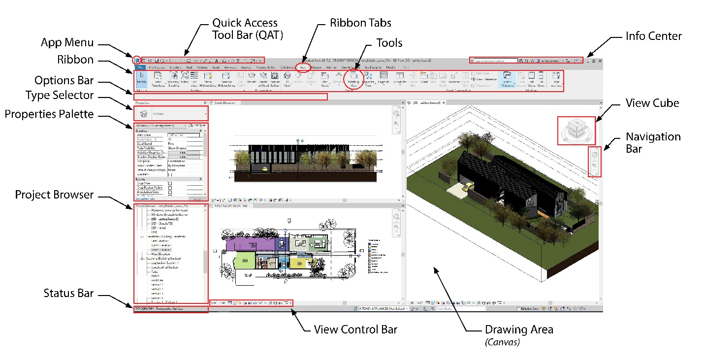 image from: uta.pressbooks.pub
in the PROJECT BROWSER (bottom left), double click on SITE. We are going to set up the extents of our building.
(You could, also, draw your property line here using MODEL LINE, but that’s later….)
GRID LINES
These help structure your structure (tee hee). They provide “boundaries,” if you will, that you will attach your walls to. They make changing structural dimensions really easy.
PROJECT TIP: You should have GRID LINES for ALL your exterior walls of your house, especially for complex floor plans.
From the RIBBON, select STRUCTURE and then GRID
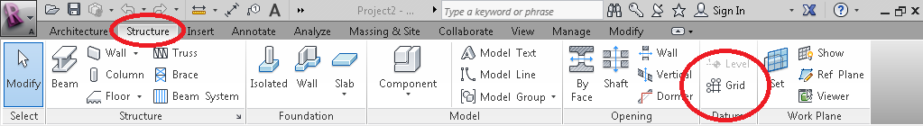
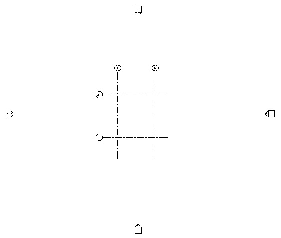
Click somewhere near the bottom of the screen and then move towards the top of the screen and click again. You can scroll in or out while you do this if you want. It doesn’t matter how long the line is right now.
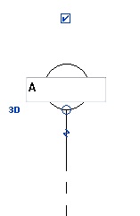
Click on the circle at the top of the line you just made. Change whatever it is (usually a “1”) to an “A” Don’t hit ESCAPE yet!
(If you can’t re-label these, you might not have grabbed the right TEMPLATE)
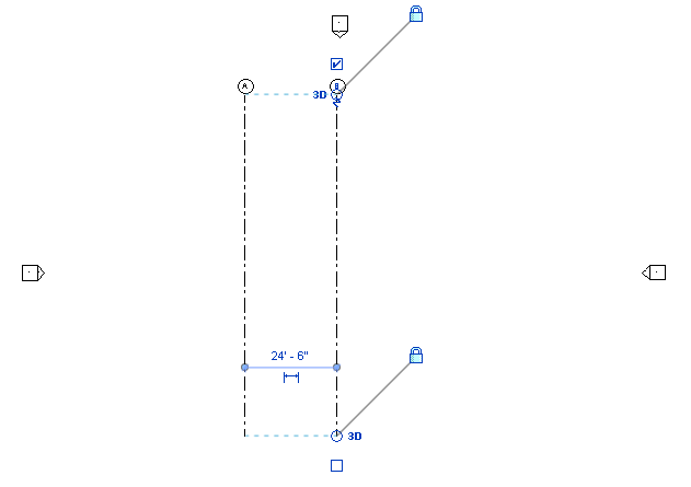
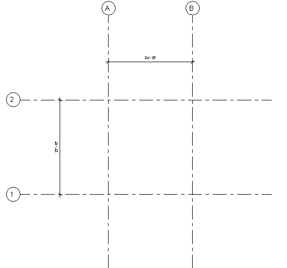
You should still be in the GRID command. Hover at the bottom of your first line for a moment, then move to the right side – you should see guiding dimensions. Click another line 24′ away, the same as you just did. Re-label it “B”
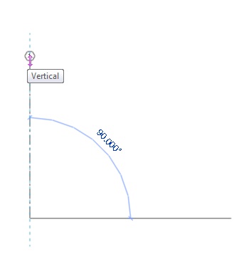
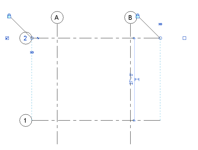
Now create two more lines horizontally, but this time 27′ apart. Label these “1” and “2”. These will outline the perimeter of our garage.
Hit ESCAPE twice to get out of GRID. Get in the habit of hovering over the ESC key – it cancels wherever you are.
“If In Doubt – Escape Twice Out.”
If your grid is not centered between all four VIEW icons (the wee house-shaped thingies), select all the lines you just drew, and then nudge the cameras to where you want them by selecting them, and using the ARROW keys.
PROJECT TIP: Your house should be centered in the cameras. You can move cameras.
PROJECT TIP: Cameras too close will start to show the inside of the house, instead of the outside of the house
A complex house design should have WAY MORE than just four grid lines – use grid lines to your advantage!
DIMENSION GRID LINES
This sets and LOCKS IN the actual size of our building. This also makes it easy to change the building, just by changing these dimensions.
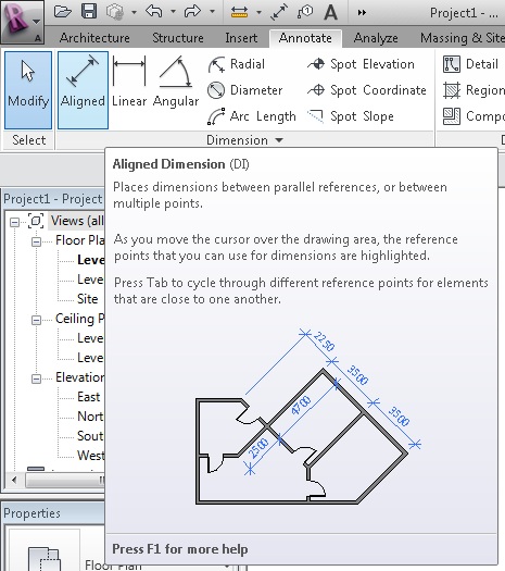
From the RIBBON menu, select ANNOTATE, then ALIGNED DIMENSION. Hover over one of your lines until it highlights, pick it, then pick the other line, then move the dimensions and pick where you want them to be.

If you need to change any dimensions, hit ESC twice, then click the grid line you want moved. This will allow you to change the dimension directly, and the drawing will automatically adjust to the new dimension.
LEVELS/LAYERS
These are much like Grid Lines, only they set HEIGHTS for things like the Foundation, the Top of the Plate, the tops of floors, etc. They make drawing walls easy, because you just draw from one level to another level. They make changing wall heights REALLY easy.
Now switch to the SOUTH ELEVATION VIEW and draw the end of the GRID DATUMS closer. Be careful to select only the CIRCLES
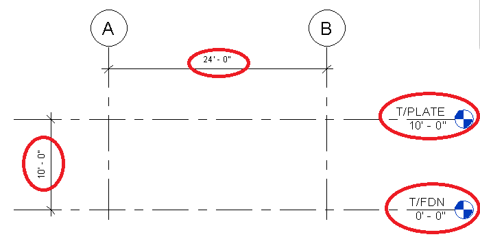
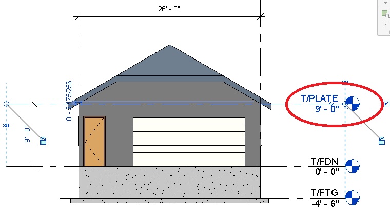
Click on the names of the two Levels shown, and rename them “T/FDN” for “Top of Foundation” and “T/PLATE” for “Top of Plate” (the two-stack of boards that make up the top of your walls). Then add some dimensions just like you did before.
PROJECT TIP: These work really well for your Elevation Heights
FUTURE HOUSE DESIGN NOTE: DO NOT create levels for Ceilings when we do Electrical. “Ceiling Views” are already linked to (and a part of) their “Floor Views.”
WALLS AND WALL TYPES
Change to the T/FDN Layer, then click WALL from STRUCTURE off the RIBBON Menu
In the PROPERTIES PANE, pick GENERIC – 8″, and then click EDIT TYPE
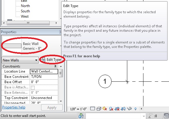
We are going to Duplicate the Generic Wall, and then edit it into something we will use. On the TYPE PROPERTIES menu, Click DUPLICATE, and name it GARAGE WALL.
LIFE LESSON: ALWAYS MODIFY A DUPLICATE – SO THAT WHEN YOU SCREW UP, YOU STILL HAVE THE ORIGINAL
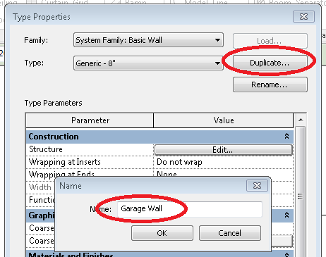
Once you have DUPLICATED the wall, we can now setup this GARAGE WALL with the way we want to build it. Click “EDIT” to do this…
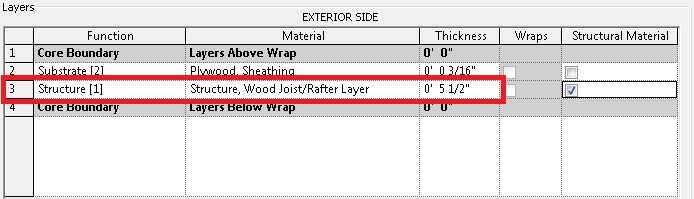
The construction of the walls are shown in the EDIT ASSEMBLY window. Note the materials from the EXTERIOR side (Top) to INTERIOR side (bottom).
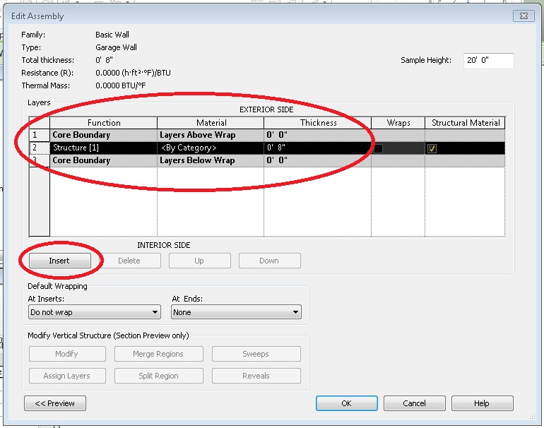
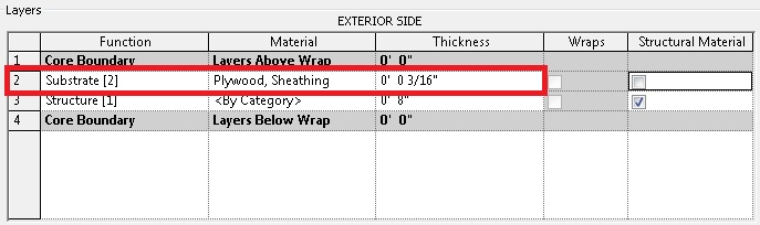
Click INSERT to create SUBSTRATE (2), and then click each section to use Plywood Sheathing, with a thickness of 3/16″ (you have to say inches = ” )
This is the “chipboard” plywood on the outside of the house, before any siding or anything is put on
And EDIT STRUCTURE (1), Structure Wood Joist/Rafter, with a thickness of 5.5″. Maybe pick the Wood Joist with Batt insulation.
These are the 2×6’s that make up your walls.
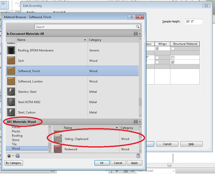
Now add another layer at the top, called Structure (1), and in selecting a Material, look for AEC Materials at the bottom, click WOOD, and in the right pane pick SIDING, CLAPBOARD. Give it a thickness of 1/2″.
This is going to be your siding.
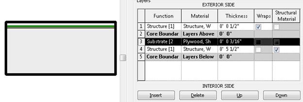
You can click on PREVIEW and see a cross-section of your wall. The wall has a CORE, and the Siding is OUTSIDE the core. When we place a wall, we select EXACTLY how we want that wall placed – Center of core, center of wall, edges of core, edges of wall, etc….
“New Hotness” wall construction today:
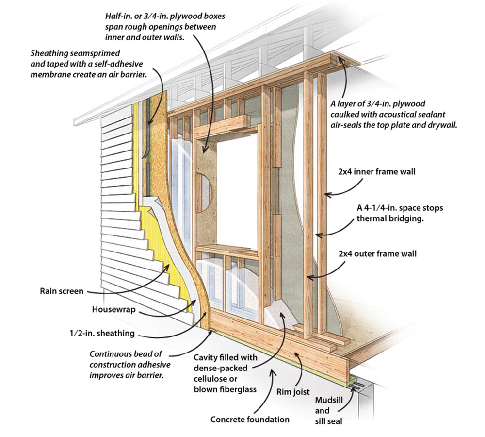 Image from: www.finehomebuilding.com
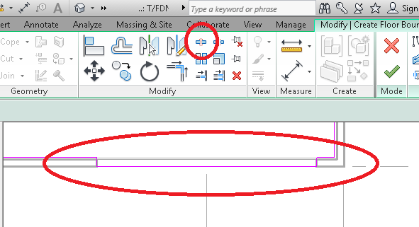
When you are done, hit ok. Pay attention to your OPTIONS BAR when you are drawing:
When you are drawing a wall, it draws from the LAYER YOU ARE ON, up to the LAYER YOU SELECT. In this case, we are drawing a wall ON the T/FDN, and the wall will go UP TO the T/PLATE:
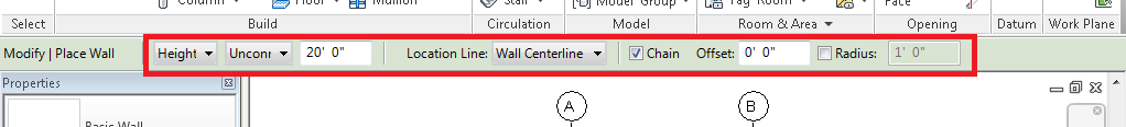
NOTE: ^^^ THIS PICTURE IS WRONG ^^^, change it so you are drawing ON the T/FDN, and go UP TO the T/PLATE, using CORE FACE EXTERIOR.
We are also going to place our walls referencing the CORE FACE EXTERIOR
DID I MENTION CORE FACE EXTERIOR? ALWAYS!
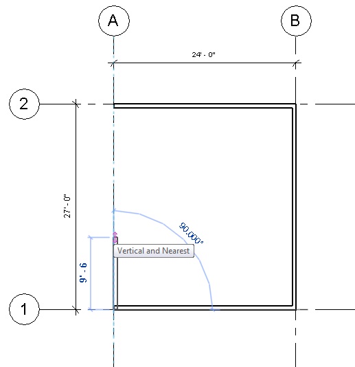
With CHAIN enabled, we can just create walls continuously, each wall adding to the last (this is fast – do this). Try drawing a wall – notice how the wall automatically snaps to the GRID lines we drew. When you click back where you started, the wall mode stops – it knows you are done.
DRAW YOUR WALLS CLOCKWISE, OR YOUR INSIDES MIGHT BECOME OUTSIDES
(YOU FLIP THEM AROUND BY HITTING THE SPACE BAR)
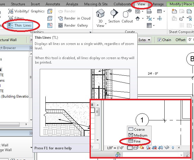
If you zoom in to your new wall, you won’t see the construction detail we just setup. To change that setting so you can see everything, go to VIEW and turn on THIN LINES – top of your screen, and then DETAIL LEVEL: FINE – bottom of your screen.
We’re going to change the Sheathing Thickness of these walls.
Click on a wall, and in the PROPERTIES Pane, select EDIT TYPE.
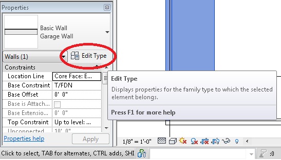
Click on STRUCTURE: EDIT, and change the SUBSTRATE (2) Plywood Sheathing to 5/16″
Notice that the sheathing thickness has been updated and re-drawn automatically.
In the RIBBON menu, select VIEW and then 3D VIEW (icon looks like a dog house), and view your handiwork so far. (You can turn SHADING on and off with the VIEW icons at the bottom of your screen)
Change to the T/PLATE layer. Notice the walls are now grayed out – they are on the layer BELOW where we now are. (We went UP a layer)
ROOF
Select ARCHITECTURE from the RIBBON Menu, and then pick ROOF by FOOTPRINT (to exit this, you need to either FINISH the roof, or hit the BIG RED X).
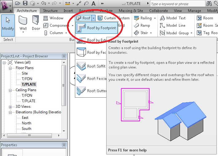
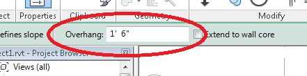
Set an OVERHANG of 18″ (1’6″)
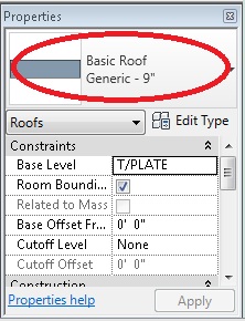
In the Roof PROPERTIES, change the roof to BASIC ROOF GENERIC – 9″
Hover over and click each wall (pay attention to which side the impending overhang shows up on). The little triangles tell you the roof slopes up. All four sides sloping up is a “Hip Roof.”

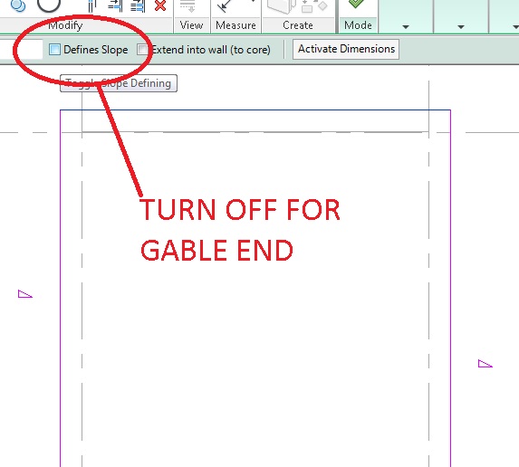
Now hit escape twice, then use CTRL to select the TOP and BOTTOM (of your screen) ends of the roof, and turn them into GABLE ENDS.
Let’s also change the SLOPE of the roof from 9″ / 12″ to 7″ / 12″

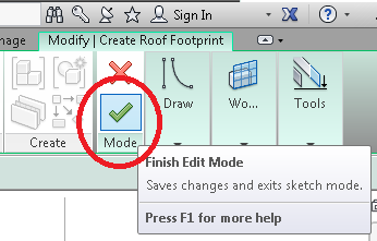
Now click the BIG GREEN ARROW to finish the roof
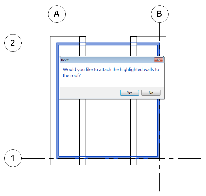
I had this menu pop up for me once while doing this tutorial. If it pops up for you, say YES. It is a good thing.
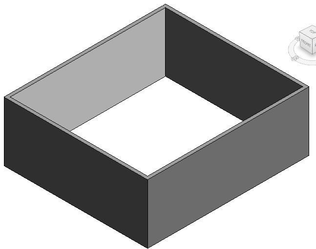
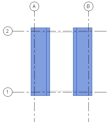
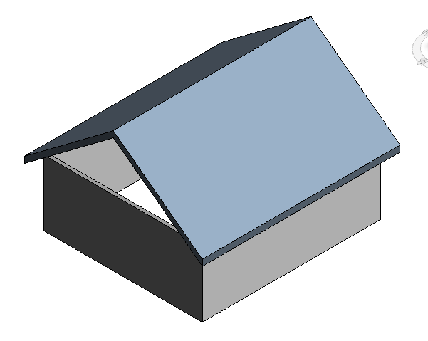
You will now see this (don’t freak out – RevIt just can’t “see” the top of the roof yet)
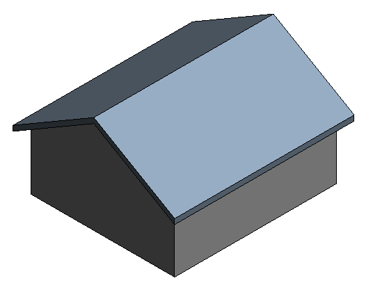
Now go 3D and have a look. If the walls do not go all the way up to the roof like shown here, we will connect them next.
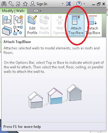
Top extend the walls to the roof, click on the “open-top” wall, and then click ATTACH TOP/BASE, and then click the roof. The wall should now attach to the roof.
Hold the SHIFT button and rotate the view using the MIDDLE MOUSE BUTTON, and do the other side.
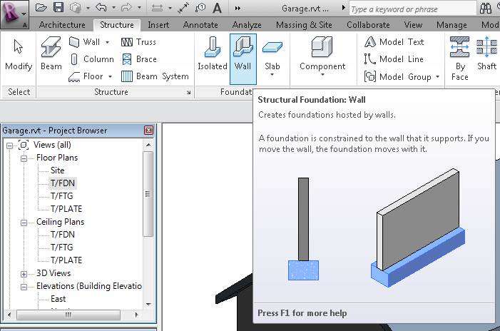
FOUNDATION WALLS
Typical buildings need FOUNDATION WALLS. A solid Foundation is CRITICAL for a building.
Foundation Walls stick out of the ground a minimum of 6″ (12″ is better), and here in this part of BC need to go a minimum of 2′ (two feet) into the ground to be “frost-free.”
Let’s build one.
Let’s create a new LEVEL for our FOUNDATION.
First, click on any ELEVATION VIEW in the PROJECT BROWSER at the left of the screen.
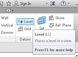
From the RIBBON Menu, select STRUCTURE and then LEVEL.
Start a new LAYER by hovering near the T/FDN Layer, and click about 5′ down. Try to make the new LEVEL LINE as long as the others.
ESCAPE twice to get out, then click and rename the new Level to T/FTG for “Top of Footing”.
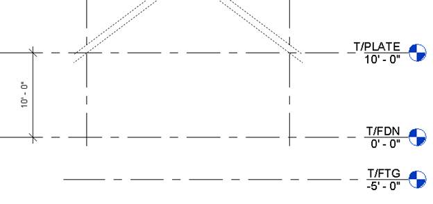
CLICK once on the -5′ 0″ dimension, and change it to -4′ 6″. Everything should adjust automatically.
Change to your T/FDN FLOOR PLAN VIEW.
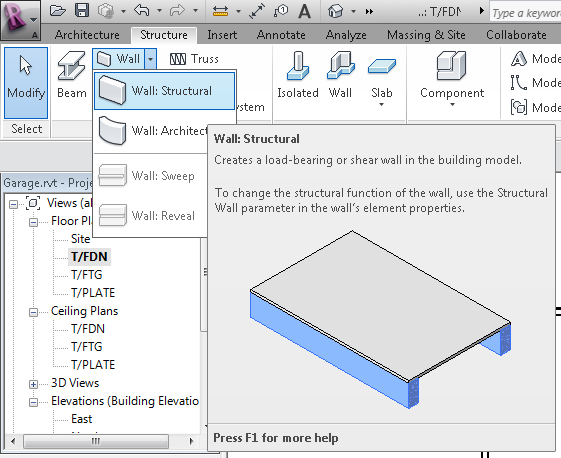
From the RIBBON Menu, select STRUCTURE and WALL: STRUCTURAL
In PROPERTIES, Pick BASIC WALL FOUNDATION – 12″ CONCRETE
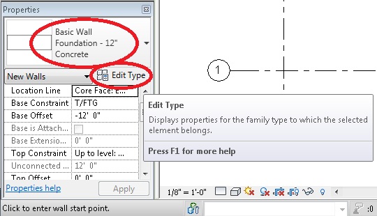
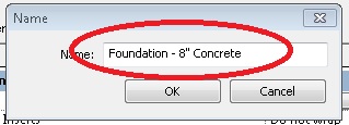
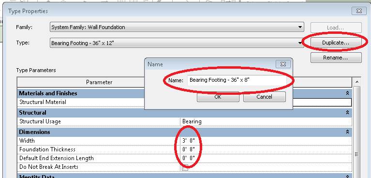
Just like we did before, click EDIT TYPE, create a DUPLICATE names FOUNDATION – 8″ CONCRETE. Change the width to 8″ as well.
Change the LOCATION LINE to “CORE FACE: EXTERIOR” so that the outside of the Foundation Walls will sit flush with the outside of the Garage Walls.
NOTE: THIS IS GOING TO GET WEIRD
RevIt thinks of FOUNDATION WALLS a little differently than other walls. FOUNDATION WALLS only draw “DEPTH” (they go down, not up) and you cannot change it to HEIGHT. You can see that option grayed out.
Settings you need to make in the PROPERTIES window:
Set the wall BASE CONSTRAINT = T/FDN
Set the BASE OFFSET = -4’6″
Set the TOP CONSTRAINT = T/FDN
(This makes the Foundation Walls START on the T/FDN level, BUT ACTUALLY START -4’6″ below that, and then draw BACK UP to where we started. Yeah, my head exploded to. Just trust me – this works)
Make sure you are drawing on the T/FDN Floor Plan. This seems so drunk to me. I’m sure there is a reason for doing it this way, but I just don’t see it.
Click on and follow the perimeter of your walls. You are drawing ON the T/FDN level, except it’s offset -4’6″, and ending up drawing UP to the T/FDN level. Drunk.
You’re going to have an error that you cannot see your walls.
Yes.
Don’t worry about it; they ARE there.
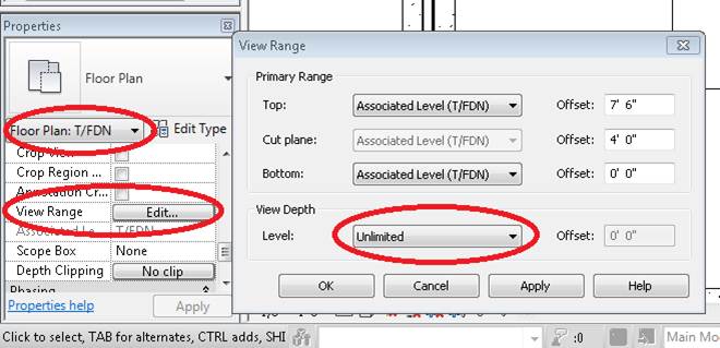
To SEE them, we’re going to make upcoming FOOTINGS visible on the this level by editing the VIEW RANGE and changing the VIEW DEPTH to UNLIMITED:
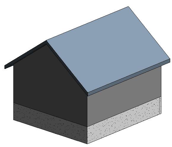
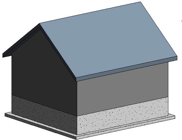
Take a look at your new foundation in 3D
You might be able to, at this point, select all the foundation walls you just drew, and edit their properties such that they now START on the T/FTG and go UP to the T/FDN if you wanted to. Advantage: you can easily change their depth by moving the T/FTG Level. You don’t HAVE to do this, but you can.
FOOTINGS
When you are building a structure, all of this needs to be resting on a FOOTING.
From the RIBBON Menu, pick STRUCTURE and then in the FOUNDATION panel, choose WALL.
REMINDER: FOUNDATION WALLS GO “DOWN,” NOT “UP”
In PROPERTIES, select EDIT TYPE, and create a DUPLICATE wall, but 36″ x 8″.
Go into 3D View mode (if you aren’t there already), and click on the base of each of your Foundation Walls. You should see the Footing show up right away. The Footing will show up at each wall you click, because it is constrained (linked) to the wall itself.
All the things we have drawn so far relate to each other. If I move the roof up, the walls will extend to meet it. If I drop the foundation lower, the footings move too. If I change the footprint of the building, everything else updates automatically. This makes it VERY EASY to make changes later on. In the bad old hand-drawn days, you had to re-draw E-V-E-R-Y-T-H-I-N-G for one moderately significant change.
ROOF WALL CLEANUP
What the heck? Here’s how to fix this:
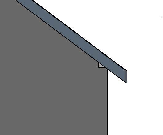
You want to go to your MODIFY Tab on the RIBBON Menu and select WALL JOINS
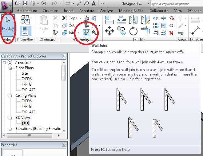
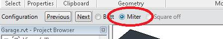
Click a corner where two walls join, then pick MITER – this should fix that gap at the roof.
Alternatively, you could just select the wall, and in the MODIFY Tab of the RIBBON Menu, select ATTACH TOP/BASE.
CONSTRAIN MODEL & FLEX
To make any changes super easy, we are going to make sure our drawing is constrained and locked to our grid lines.
Go to your T/FDN LAYER
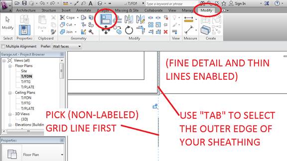
From the MODIFY Menu, select ALIGN
Click the un-labeled end of one of your grid lines, then use tab to select the exterior edge of the wall sheathing. You may need FINE DETAIL and THIN LINES enabled to see this. This may actually take a few tries until it does what you want. Honestly, I found this part the most annoying.
When you have the Wall and Grid Line constrained and locked, you should see this additional PADLOCK appear when you select it.
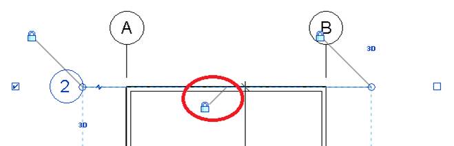
Do the same thing to your T/FTG plan, so your FOUNDATION WALLS are constrained and locked as well.
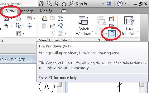
Go to the VIEW Tab in the RIBBON Menu, and select TILE WINDOWS.
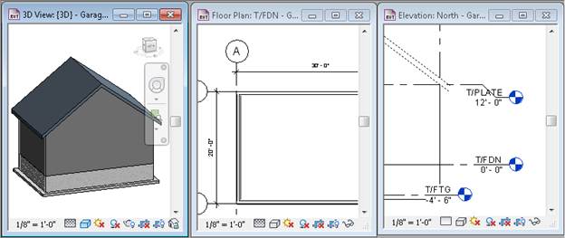
You can rearrange or delete the views however you like. For now, DELETE all but the T/FDN, 3D, and ELEVATION: NORTH windows. This can make it easier moving around from view to view.

In the ELEVATION view, change the T/PLATE height from 10′ to 8′. Notice how everything adjusts. Now change it to 12′.
In the FLOOR PLAN view, Click on GRID LINE B, then unlock and change the Garage Width from 24′ to 30′ (If the Foundation Walls do not follow – you need to check your ALIGNS – FIX IT!!)
Also in the FLOOR PLAN view, click on GRID LINE 1, then unlock and change the Garage Depth from 27′ to 20′.
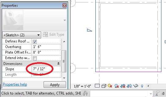
Click on the ROOF, and in Properties, change the Slope from 7″ / 12″ to 9″ / 12″. Note the change.
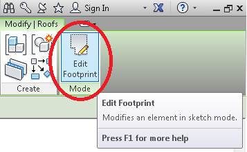
While the ROOF is still selected, click EDIT FOOTPRINT
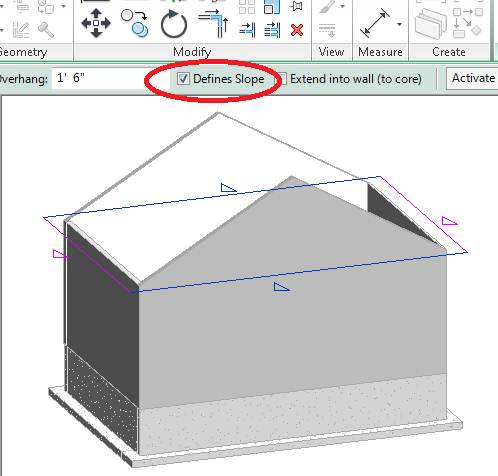
Now select both non-sloped sides (use CTRL to help select both), and then select DEFINES SLOPE
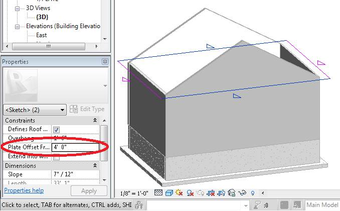
Now change the PLATE OFFSET FROM LEVEL to 4′
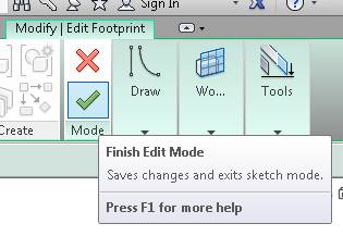
Finish the ROOF with the BIG GREEN CHECKMARK
Nice eh?
Now click on GRID LINE B, and change the Garage Width to 26′
Click on GRID LINE 1 and change the Garage Depth to 26′
Check that EVERYTHING adjusted accordingly. If it didn’t, you may have to go back and constrain some more (I had to constrain at different levels for whatever reason).
WINDOWS AND DOORS
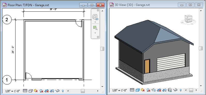
I’m going to change my views just a bit, so I can see the T/FDN Floor Plan as well as the 3D View.
From the ARCHITECTURE tab of the RIBBON Menu, select DOOR
!!RECENT DISCOVERY!!
!!SUPER EASY!!
From the RIBBON menu, go to INSERT and select “LOAD AUTODESK FAMILY”
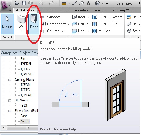
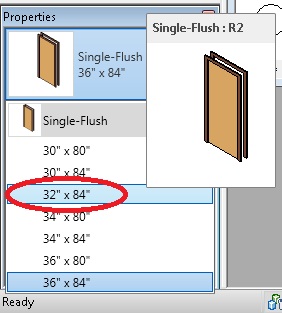
In the PROPERTIES Pane, change that door to a 32″ x 84″
Note: ALL exterior doors are really 36″ wide. The video I followed for this tutorial called for a 32″ wide door. In real life, you’ll wish you had a 36″ door.
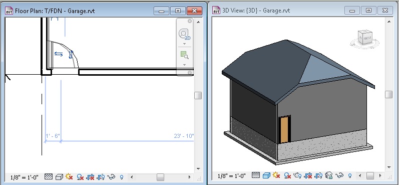
Hover over a wall, and you will be able to place that door. If you move your mouse towards the inside or outside, you can change which way the door opens (Residential House Doors open IN, Business Doors open OUT). Hitting SPACE will change whether the door opens RIGHT or LEFT
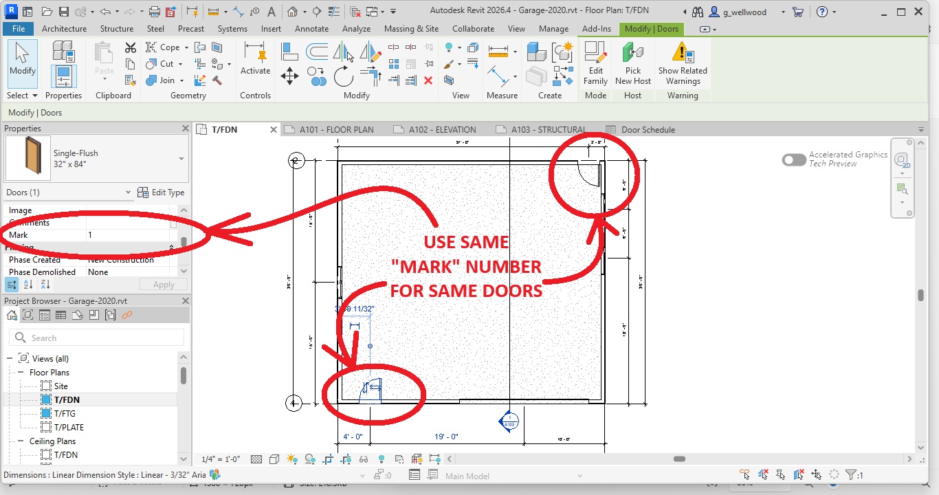
TAKE A MOMENT NOW TO FIND “MARK” FOR YOUR DOOR IN THE PROPERTIES WINDOW
MAKE SURE EVERY SAME DOOR AND WINDOW YOU USE SHARE THE SAME MARK (YOU CHANGE IT!)
YOU CAN THANK ME WHEN YOU DO YOUR DOOR & WINDOW SCHEDULE FOR YOUR HOUSE!
To install a Garage Door, click on LOAD FAMILY from the RIBBON Menu, and navigate to the DOORS folder go to INSERT -> LOAD AUTODESK FAMILY button
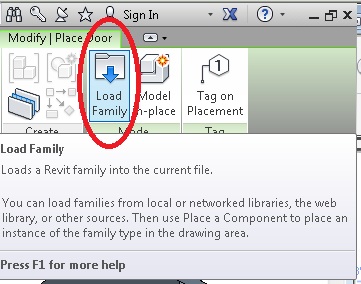 Load AUTODESK FAMILY, not “LOAD FAMILY” as shown
Let’s pick an OVERHEAD SECTIONAL Door.
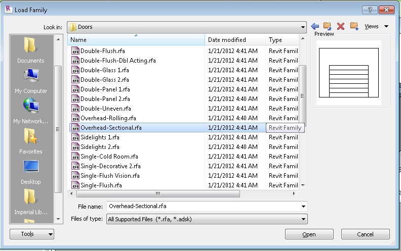
Place it on a wall, with the panel on the inside.
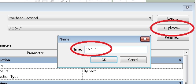
Once it is in place (hit ESCAPE twice), click on it, and EDIT TYPE from the PROPERTIES Pane. Change the name and the dimensions to 16′ x 7′ (you change the actual size in the PROPERTIES pane, not the EDIT TYPE window)
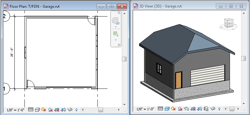
Let’s add some windows by selecting WINDOW from ARCHITECTURE on the RIBBON Menu
The default windows are all fixed, so go to LOAD FAMILY and from the WINDOWS folder INSERT -> LOAD AUTODESK FAMILY button, pick a cool window that you like (but not too big)
Place a couple windows just like you did with the doors. Place one in the middle of the WEST wall, and two on the EAST wall
Wow. That looks absurdly tall. Let’s drop the roof down a bit – go to the SOUTH ELEVATION VIEW and change the height of the T/PLATE LEVEL to 9′. That looks better.
Why am I getting you to make changes like these? To show you how easy it is to make changes, instead of a complete re-drawing. Thanks for asking!
CONSTRAIN WINDOWS AND DOORS
Make the T/FDN LEVEL full screen, and then from the RIBBON Menu, pick ANNOTATE and then ALIGNED DIMENSION
Pick one of the GRID LINES as a reference and then pick the CENTER of the door (if you are close, it will snap to it for you – you will see a text box show up when you are there).
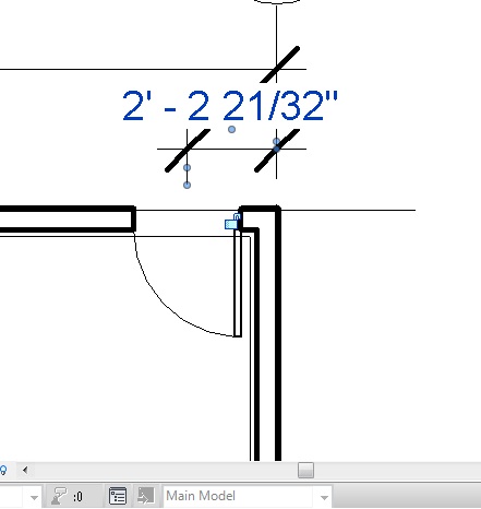
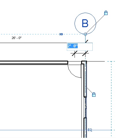
You can change the dimension after the ANNOTATION is placed by clicking the GRID LINE it is referencing. This allows you to then click the numbers and change them to what you want. You MAY need to UNLOCK the dimensions to change it, but be sure to LOCK it once you’re done. Make it 2′. Also watch that the Garage Width Dimension is also locked! (That’s grid-to grid; if it moves, it isn’t locked)
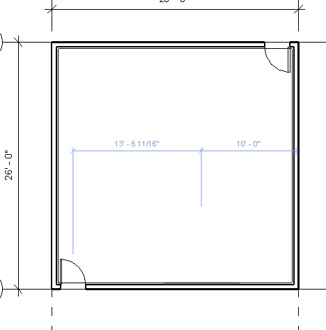
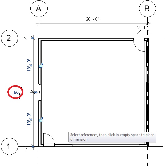
Dimension the location of the WEST window, by clicking on GRID LINE 2, the CENTER of the Window, and then GRID LINE 1. Click somewhere to locate the dimension line, and then click EQUALS – this makes sure that window will always be centered, regardless of how we change the Garage Dimensions later.
Dimension the two East windows, by clicking GRID LINE 2, then the CENTER of each window (watch for the text box reference to appear). If the Garage itself changes dimension, UNDO and go LOCK the Garage DEPTH Dimension. Lock the windows at 6′ as shown. (You can nudge the individual windows a bit by selecting them and them using the arrow keys)
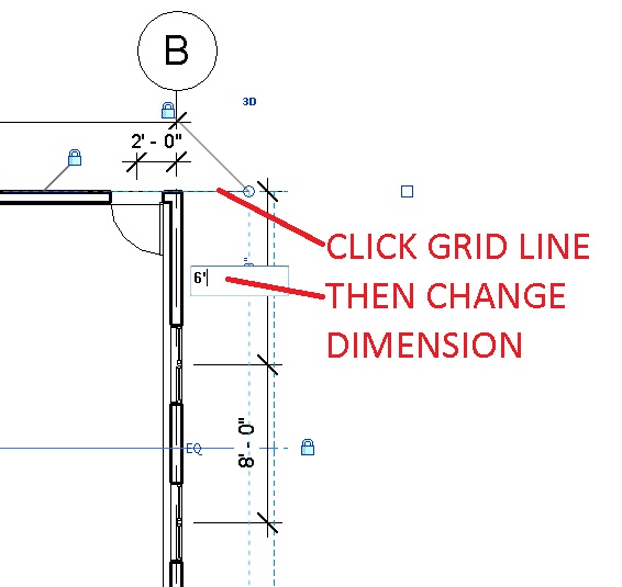
NOT 8′??? You can change the middle dimension by clicking on a WINDOW, and then clicking on the dimension to change it to 8′.
Now, imagine you get a big budget increase, and you can now build 30′ x 30′! Click on the GRID LINES and change the length and width to 30′ x 30′
(if the foundation does not move with the walls – you need to go back and CONSTRAIN them to the GRID LINES!).
Notice with the new dimensions, everything adjusts itself, maintaining the CONSTRAINTS you set.
LOWER GARAGE DOOR
Most Garage floors are sloped to allow drainage. Let’s lower the Garage Door, and add a slab.
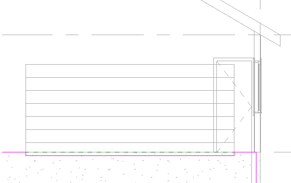
Select the South Elevation view, select the Roll-Up Door, and go into Properties and change the Sill height from 0′ 0″ to -3″ – this lowers the door 3″.
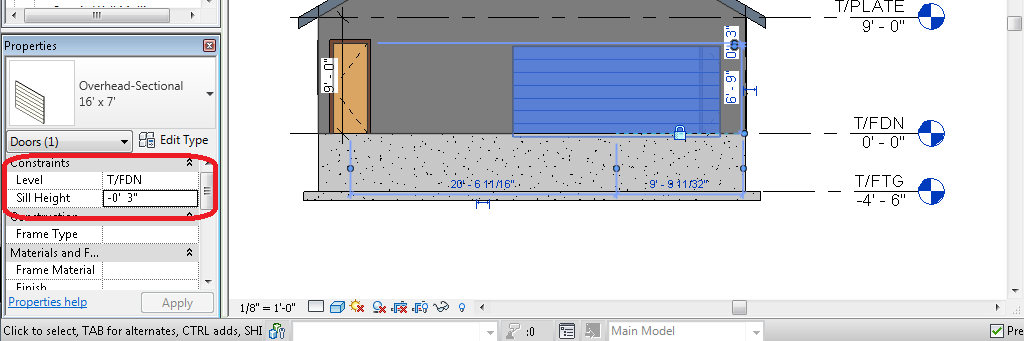
You can see the door is now sunk into the foundation wall. We need to cut out the foundation wall.
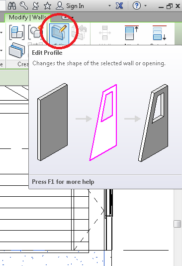
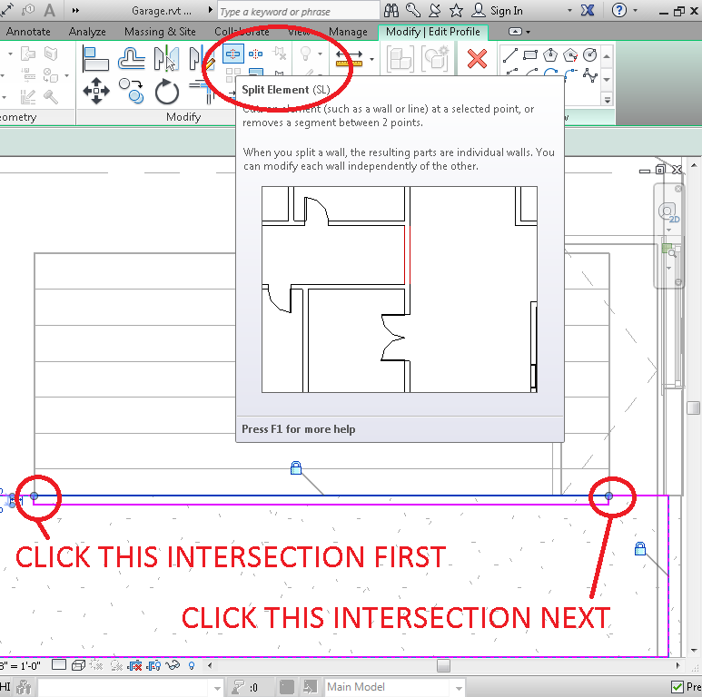
Click the Foundation Wall that we will be notching, and from the MODIFY menu, pick EDIT PROFILE.
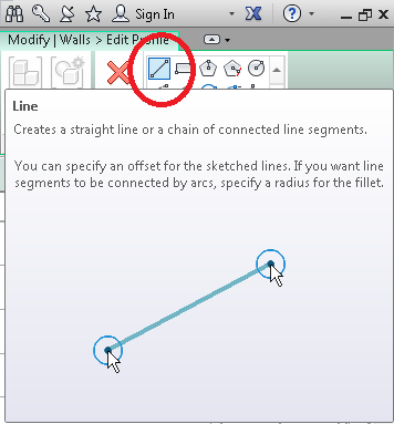
You can now either sketch lines, or pick lines to create our “notch.” From the MODIFY menu, select DRAW and draw lines along the bottom of the door.
REVIT does not LIKE OVERLAPPING LINES, or lines THAT GO NOWHERE. Make sure you don’t have those.
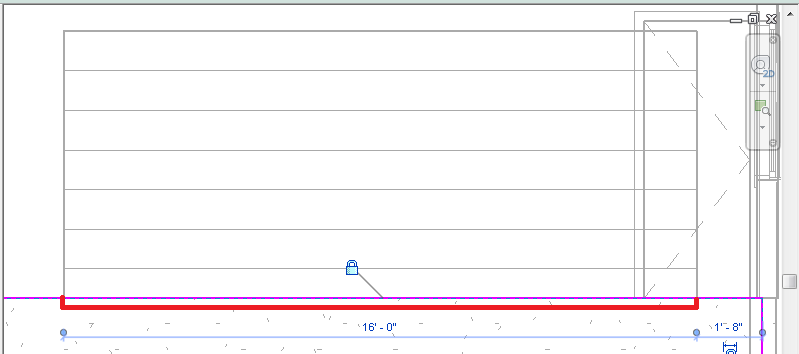
Now select SPLIT ELEMENT, and click the intersections of the foundation and door. Surprisingly, you don’t have to be really precise with this – it’s usually pretty good at figuring out what you are after.
Now you can click on the line section and delete it. There it is: gone!
Click the Green Checkmark and you’re done.
NEW FLOOR TYPE
From the ARCHITECTURE tab on the RIBBON MENU, pick FLOOR.
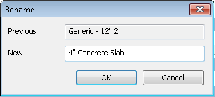
Let’s create a new floor type by going into the Project Browser on the left hand side of your screen, right-clicking on a floor type that’s close, and DUPLICATE it.

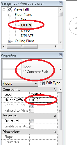
Double-click the new floor type, and rename it to 4″ Concrete Slab
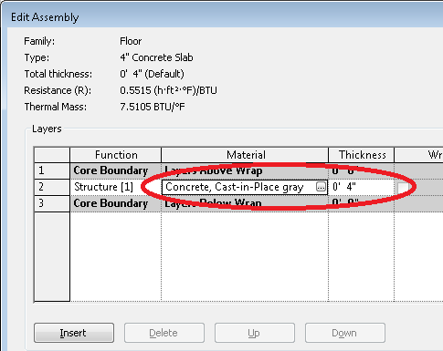
EDIT the STRUCTURE to be 4″ thickness, and a material of “Concrete, Cast-in-Place”:
CREATE SLOPING SLAB
Make sure you are on T/FDN for this part
From the top menu pick FLOOR, select the 4″ Concrete Slab we made, and change the Height Offset to -2″
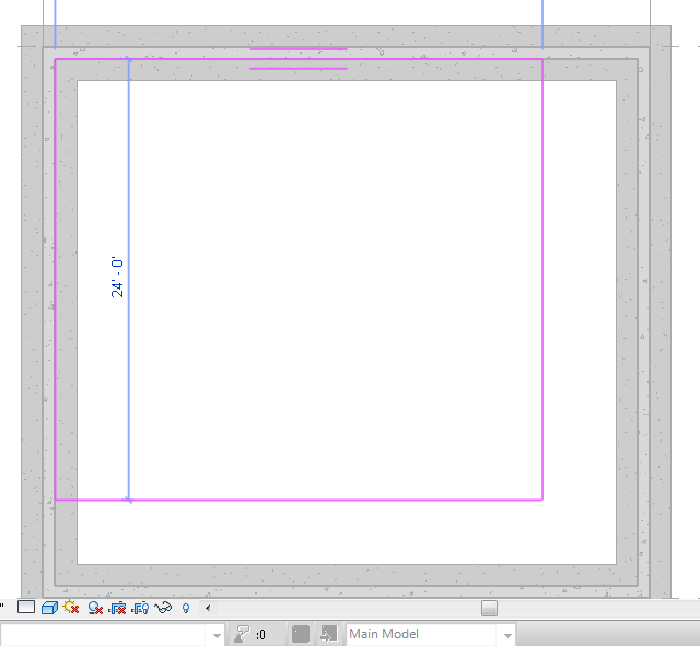
Now all you have to do, is sketch in your floor slab.
You know what? I changed my mind. It might be easier to pick the foundation walls on the T/FTG layer instead. Don’t exit anything – just click to select T/FTG and then use the RECTANGLE tool, and pick from the top left of your inside Foundation Wall to the bottom right of your inside foundation wall.
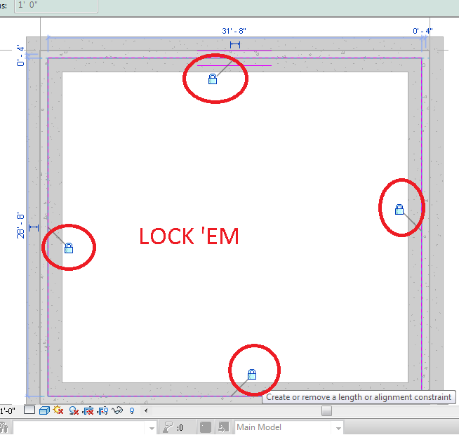
Once the slab is drawn, go ahead and lock the slab in place (don’t exit yet).
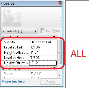
While you are still in there, select SLOPE ARROW, and click near the top of your slab, drawing the arrow towards the Roll Up Door. A sloped slab allows all the oily goo from your rusty Chevy to dribble out of your garage.
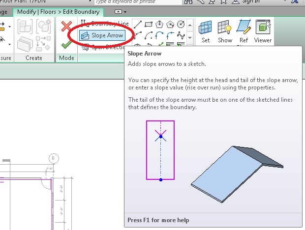
Set the amount of slope as you see below. The default slab is steeper than a rusty old Chevy can climb.
Now switch back to your T/FDN layer, and we’re going to SKETCH and SPLIT out an opening for the roll-up door.
Actually, it might have been easier to draw the slab using LINE, and then you could edge out all the doors at once. Oh well.
SHOW YOUR SUCCESSFULLY COMPLETED GARAGE TO YOUR INSTRUCTOR IN ORDER TO GET YOUR PROPERTY