NOTE: THIS TUTORIAL IS BASED OFF THE VIDEO SHOWN BELOW. BE SURE TO FOLLOW THE MARKS SHEET FOR WHAT I’M LOOKING FOR
Let’s clean up our East Elevation and add some Annotations. Switch your East Elevation View.
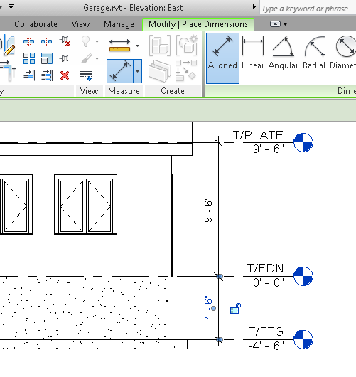
Below, I will show how to use ALIGNED Dimension to add dimensions between T/FTG and T/FDN and T/PLATE.
MrW TIP: Just use your LEVELS instead; they are already dimensioned. You’ll need to add a new level for the roof peak.
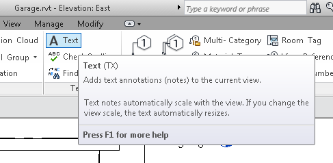
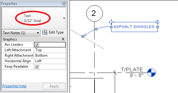
In the ANNOTATE menu, select TEXT
Then select CURVED because curved leader lines look cool.
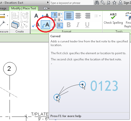
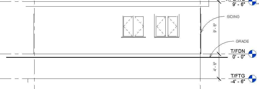
Then click somewhere on the roof (where the arrow will be) then click away where you want the text to be. Let’s call for Asphalt Shingles. You can change the text height to something appropriate. I liked 3/32″ for mine.
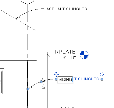
The text isn’t “intelligent” – it is not “linked” to anything, so let’s click on it, CTRL-C to copy, and CTRL-V to paste, move it down to the siding, and rename it SIDING.
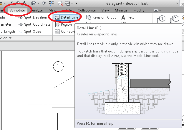
Elevation Views always show a GRADE line – so we know where the ground is. Most of the foundation will be below the Grade.
To do this, go to ANNOTATE and pick DETAIL LINE (DETAIL LINES are part of the annotation, MODEL LINES are part of your house)
Then pick WIDE LINES (they won’t look wide until you turn THIN LINES off in your VIEW DISPLAY).
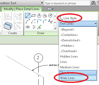
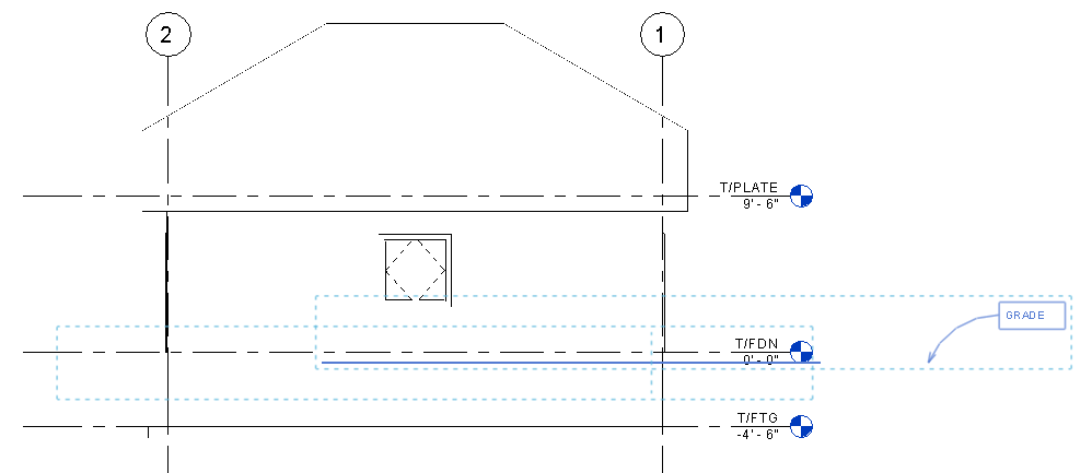
Draw a horizontal line (or sloped, if you want a sloped property line, or curved, or whatever) around the bottom of the Garage-Door/Slab-Opening. Copy the Text down, and label it “GRADE.”
Let’s Select (CTRL and CLICK) both the GRADE line as well as the TEXT. CTRL-C to copy, and go place it on the other Elevation Views (North, West, South). There will be a “shadow” to help you place the copied line. Match the height, but move the line horizontally so that it looks centered with your building. You can nudge these lines and text around using the ARROW keys if need be.
Let’s go back to the EAST ELEVATION and add some more dimensions. Most plans show height (off grade) and width dimensions, as well as height to Eves (off Grade). Let’s add them now (I used ALIGNED Dimension):
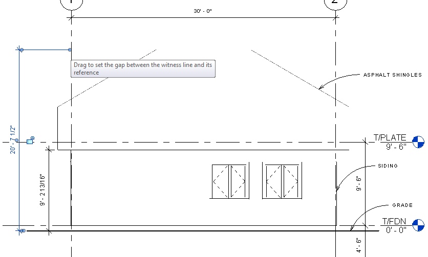
DO NOT add a width dimension as shown above – width is on your FLOOR PLAN drawing.
Nice. But having an accuracy down to 1/16″ (or less!) is a bit much. Let’s make that easier for our framers by going into MANAGE, and PROJECT UNITS, click the LENGTH setting and change it to “To the nearest 1/2”:
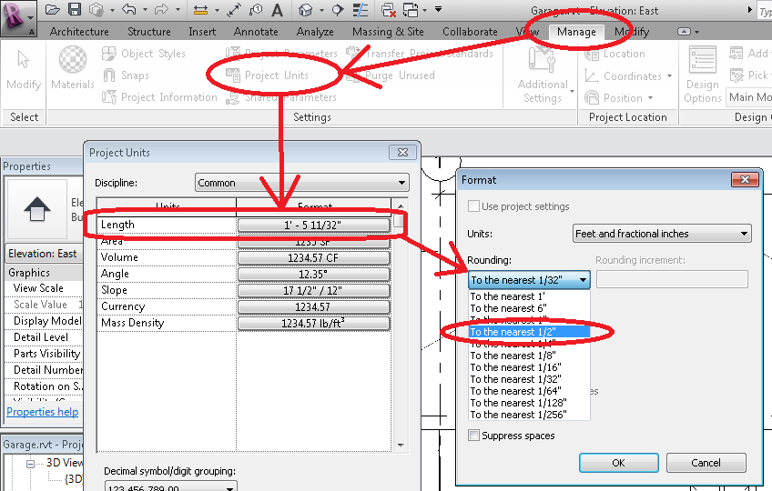
That should make the contractors happy. We didn’t change any dimensions, we just changed how “accurate” the dimensions have to be.
ANNOTATE OTHER ELEVATIONS
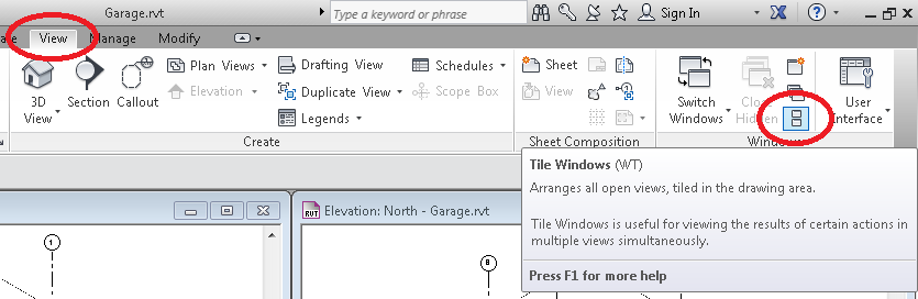
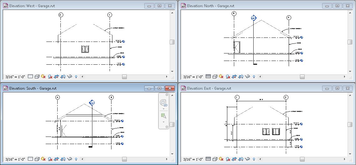
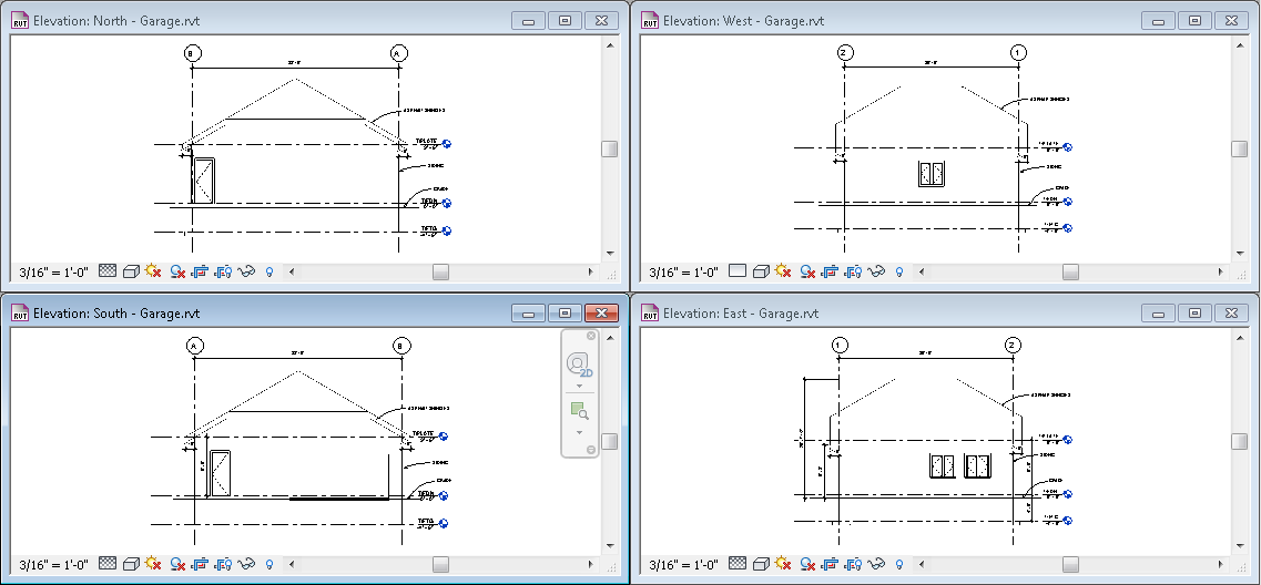
To make annotating the other views easier, double click on each Elevation View, one after the other, and then click TILE WINDOWS to place all four Elevation Views on the screen.
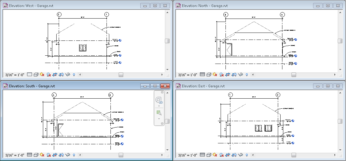
Use CTRL-C and CTRL-V to copy and past the ROOFING and SIDING text to the other views. It is so easy to switch to each view when they are all tiled. Use the ARROW keys to nudge them into perfection.
Eves and Peak heights should be on all the views. Do not add a width dimension as shown here.
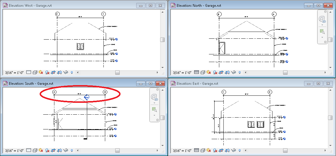
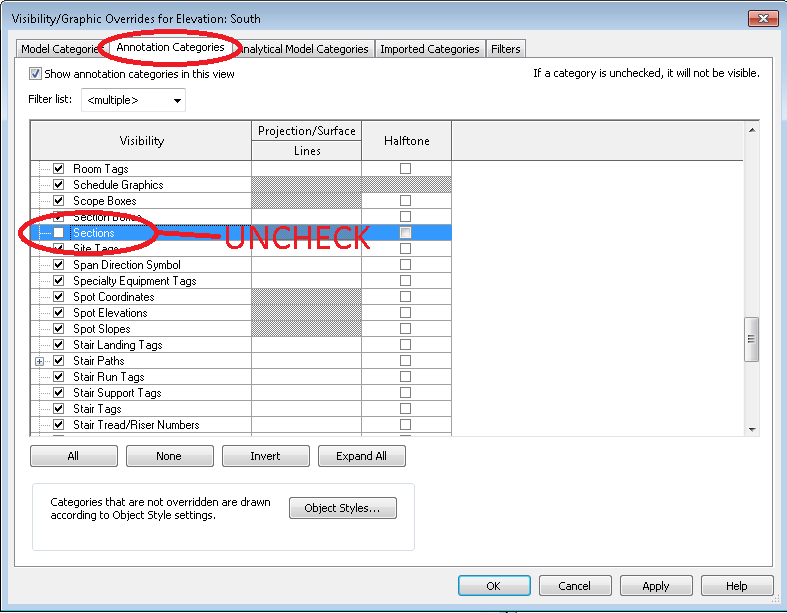
Notice the SECTION MARKERS are visible in the North and South Elevations? Ewww. We don’t need to see those – let’s turn them off. Click into one of those elevations, type VV on your keyboard, select ANNOTATION CATEGORIES, scroll down to SECTIONS and un-check their visibility. Do the same on both Views.
We will need an overhang dimension. Pick one of the views, and add a dimension from the OUTSIDE of the wall to the end of the overhang. You may need to use TAB to correctly pick that edge (not the center, or core edges, or grid line).
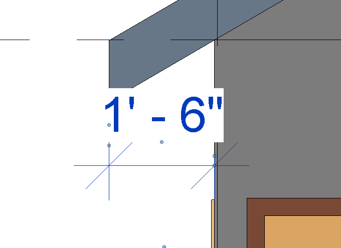
I turned shading on just so you can see better.
Add this dimension to ALL the overhangs in ALL the views.
I added heights to these views:
Yay.
This tutorial follows the video I stole it from.
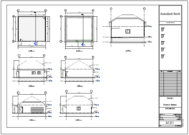
YOU WILL PUT EACH FLOOR PLAN ON ITS OWN SHET
YOU WILL PUT ALL ELEVATIONS ON ONE SHEET
YOU WILL PUT YOUR SECTION VIEW ON ITS OWN SHEET