Fusion 360 – Finite Element Analysis
I’m learning this myself. Learn to learn. Teach yourself something. Make yourself employable.
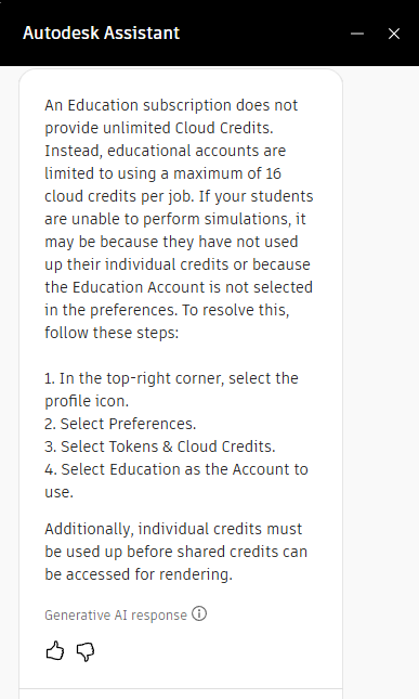
FIRST – you need to make sure you have CREDITS to do simulation!MAKE SURE your Fusion Preferences are set to EDUCATION! |
 |
Open your Steam Engine project from Tutorial 1.
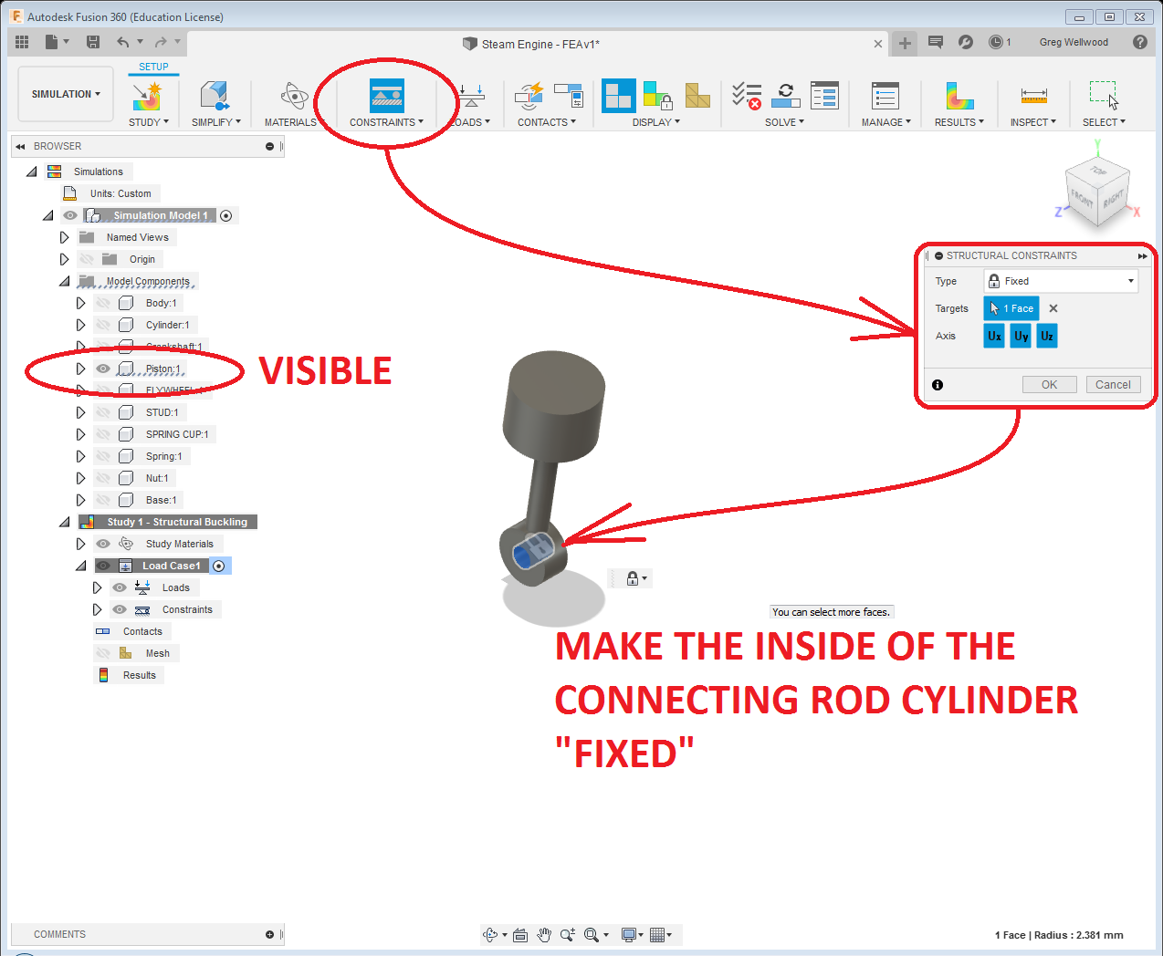
Turn off the visibility of ALL the components except the piston (if you built the steam engine correctly, all the components should be in a row just like you see below, with NO parts being “children” of other parts).
If you have ANY parts not fully constrained (JOINED), this WILL NOT WORK. Go back and MAKE SURE they are FULLY CONSTRAINED.
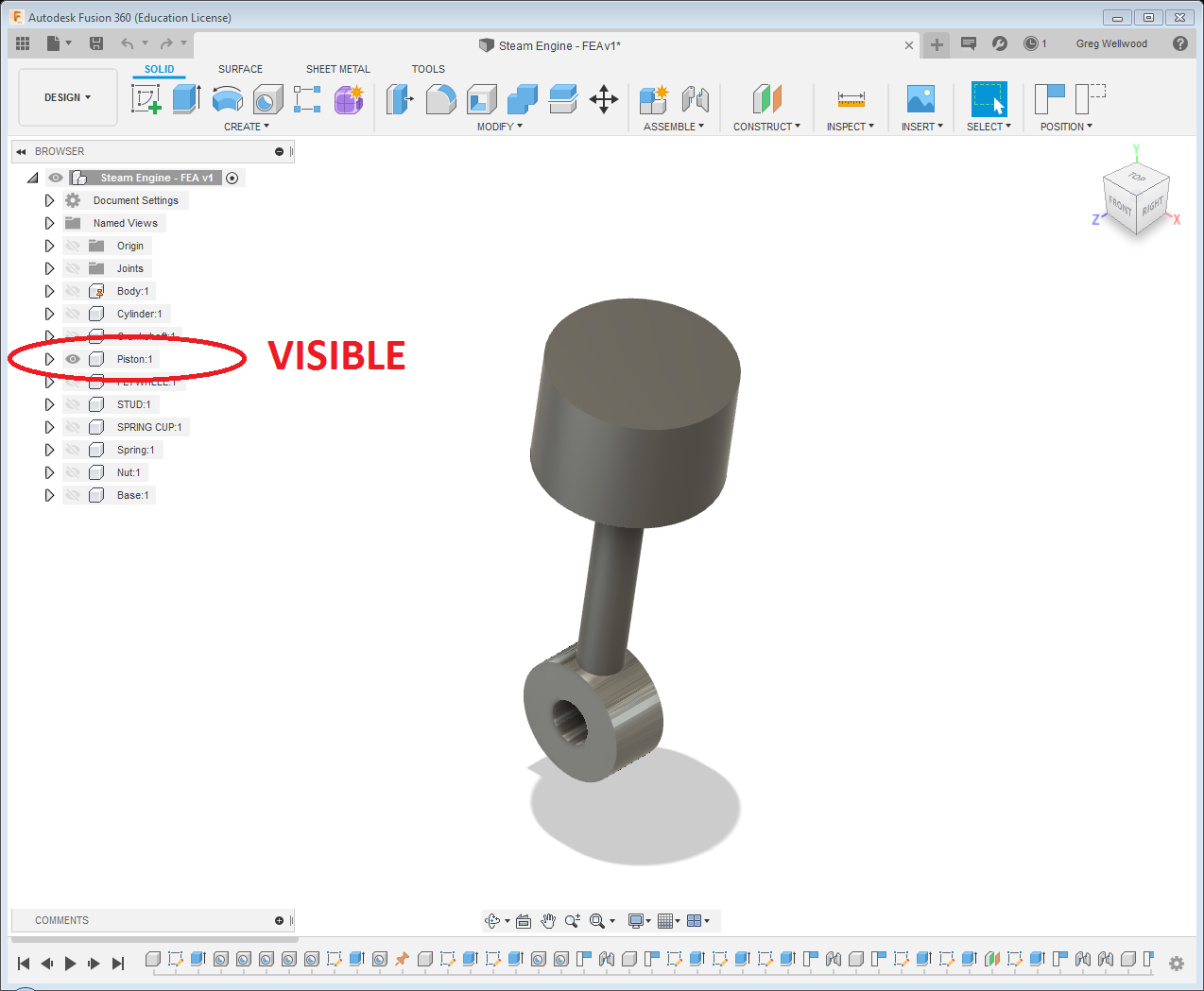
NOTE: the center rod of the Piston is the CONNECTING ROD.
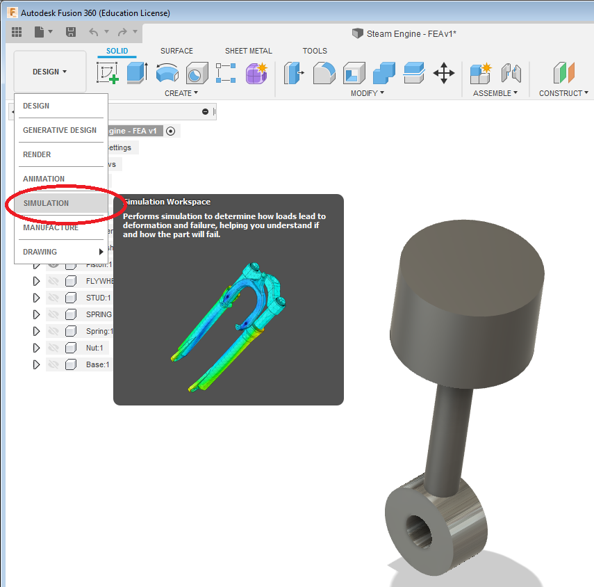
From the RIBBON MENU, change from DESIGN and go to SIMULATION
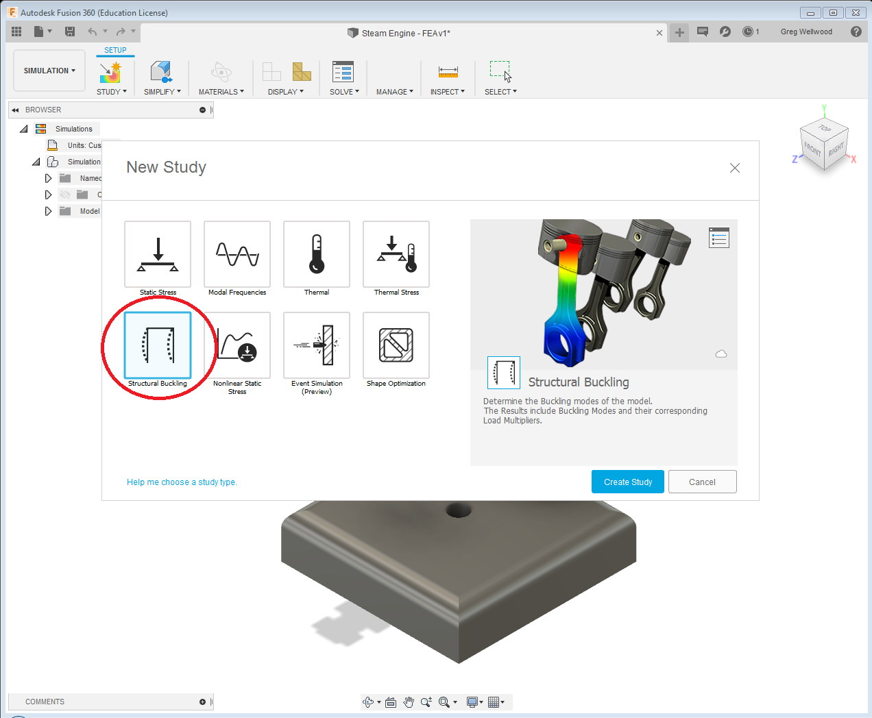
Once you get into SIMULATION, a window will pop up giving you choices of how you want to test your component. The first test we want to do is to compress the part until it buckles (collapses under pressure). Select “STRUCTURAL BUCKLING” and click CREATE STUDY.
For this test to work, we need to CONSTRAIN the part we want to test. One end will be FIXED, and the other will have PRESSURE applied to it. Select CONSTRAINTS from the RIBBON MENU and FIX the surface inside the bottom of the connecting rod so it’s won’t move.
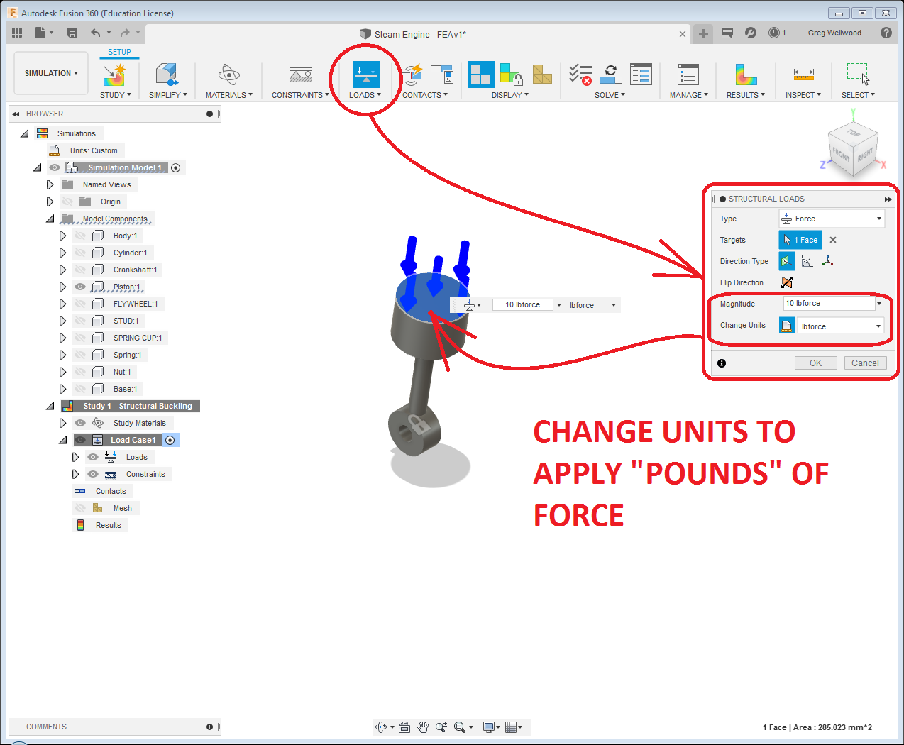
Now let’s apply a FORCE to the top of the piston. Select LOAD from the ribbon menu. Newtons is the default, but I’m old and grey, and I think in POUNDS. Change the units to POUNDS (lbs), and select the TOP of the piston. (I chose 10lbs, but DO NOT do so – keep it at 1lb of force – I’ll explain later).
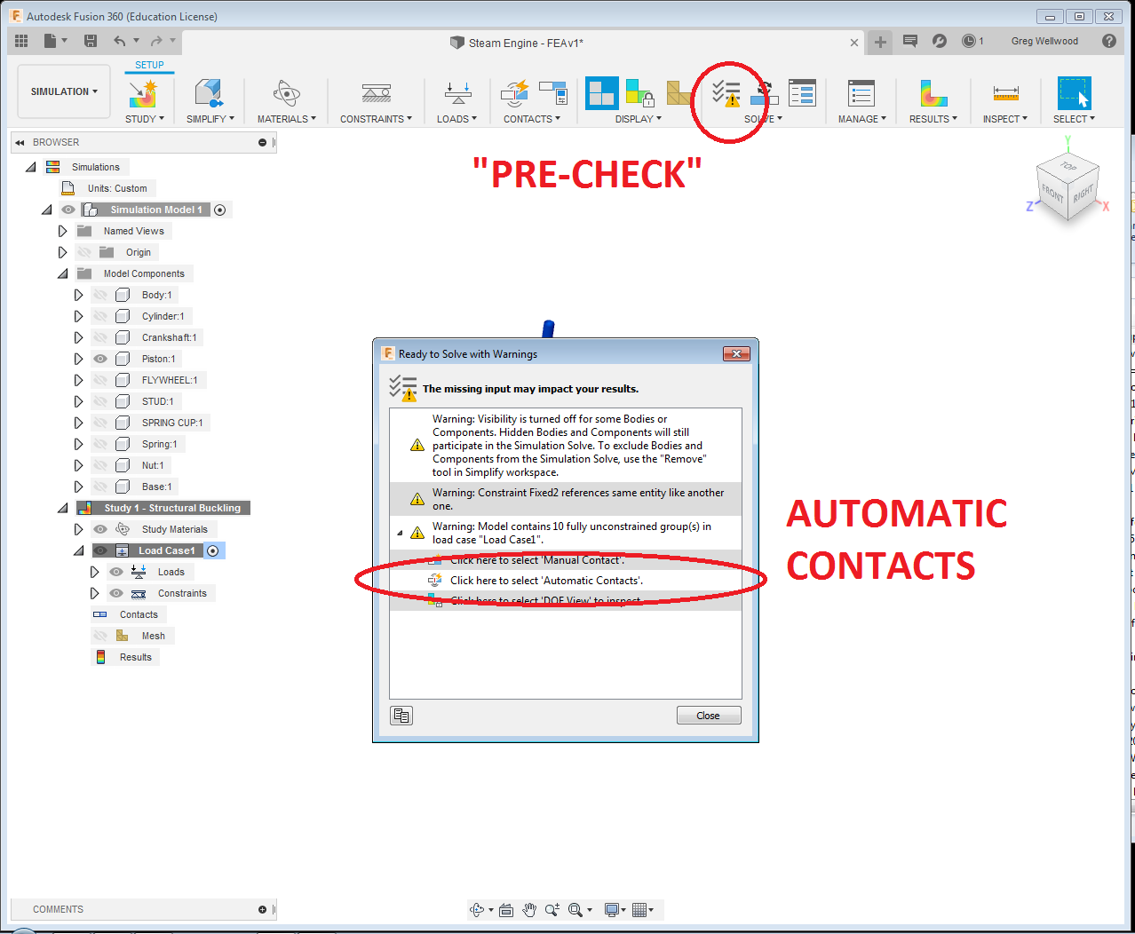
I clicked on “PRE-CHECK” just to see what might happen. It gave me some cautions, most of which I ignored. There is a big caution that says (essentially) “just because it’s invisible, doesn’t mean it’s not included in the test.” I chose to ignore that one for now.
I did, however, select “AUTOMATIC CONTACTS” because I figured that would be an easy button, left the TOLERANCE alone, and hit GENERATE.
Then, I clicked SOLVE, ignored any warnings, and click SOLVE 1 STUDY. It chugged away for a while, and gave me this:
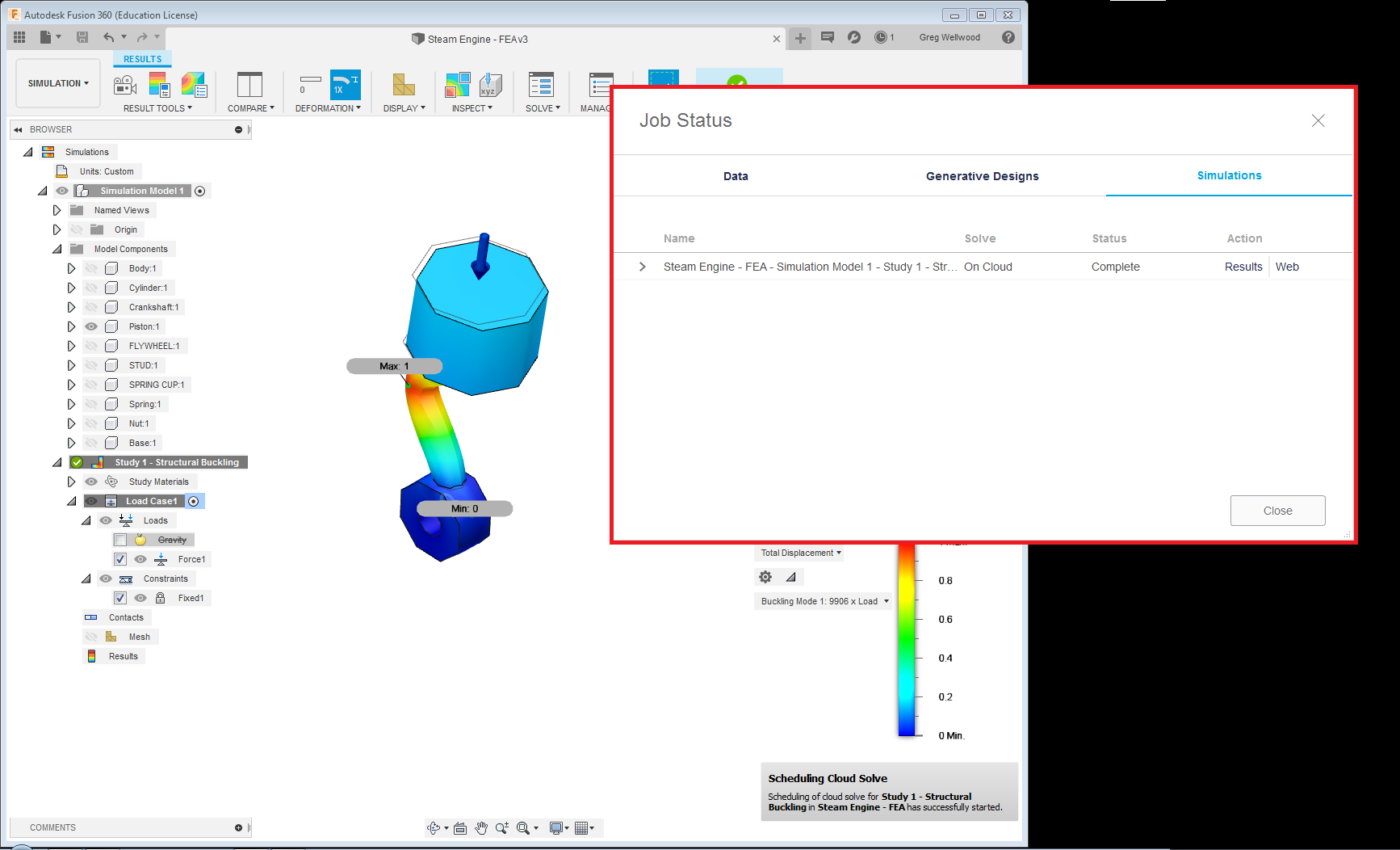
Which then begs the question: “What the heck am I looking at, Mr. Wellwood?”
Well….
Fusion simulates how the force on the piston would affect the connecting rod. It has discovered that at 9906xLoad is the fail point. since I put 10lbs of force on the piston, it will fail at 99,060lbs.
NOTE: I should have just used 1lb instead of 10lbs. The reason being – it will simulate the failure point regardless of the load I initially place on it.
I re-ran the test at 1lb force, and it told me that it would fail at 99,058lbs (99058xLoad, but load is 1, so it’s telling me the exact amount of force to break it).
It’s certainly easier to just see the actual failure point rather than have to do math (multiplying the result by the load).
Let’s change the material it is made out of. The default is steel. Let’s try 6061 Aluminum. 6061 doesn’t like to be bent. Change the material, and re-run the test.
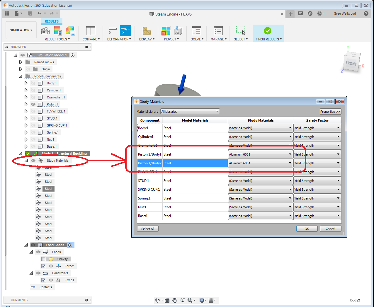
What result did you get?
SHOW YOUR TEST RESULTS TO YOUR INSTRUCTOR
(I ran a test with ABS Plastic as the material, and got a failure point of 31,089lbs)
ENGINEERING THE PISTON
When a product is engineered, it is usually built to withstand TWICE the forces it will ever see. What force will the connecting rod ACTUALLY see, if we apply 100psi (pounds per square inch) air pressure to the top of the piston?
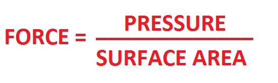
To solve this, you need to find the surface area of a circle that is 0.75″ in diameter. SA=3.14 x r2 Do math. Calculate the FORCE.
Once you have the FORCE calculated, MULTIPLY IT BY 2. Is the connecting rod strong enough as is? Go back to the design, and CHANGE the connecting rod diameter and retest until it can withstand ONLY TWICE the expected load.
Don’t give this information to your friend for free – that is how your company goes out of business. Make THEM work for it too.
SHOW YOUR TEST RESULTS TO YOUR INSTRUCTOR
The diameter you ended up with is not realistic – the connecting road does not only receive a force directly on it, it must lock the top and bottom together at speed, which is a COMPRESSIVE FORCE when the piston goes down, a TENSION FORCE when the piston goes up, and since it is rotating it is a TORSIONAL FORCE AS WELL. Since it changes direction, it also must deal with the MOMENTUM of the top and bottom.
Put it back to 3/16″ diameter, and continue:
ENGINEERING THE CRANKSHAFT
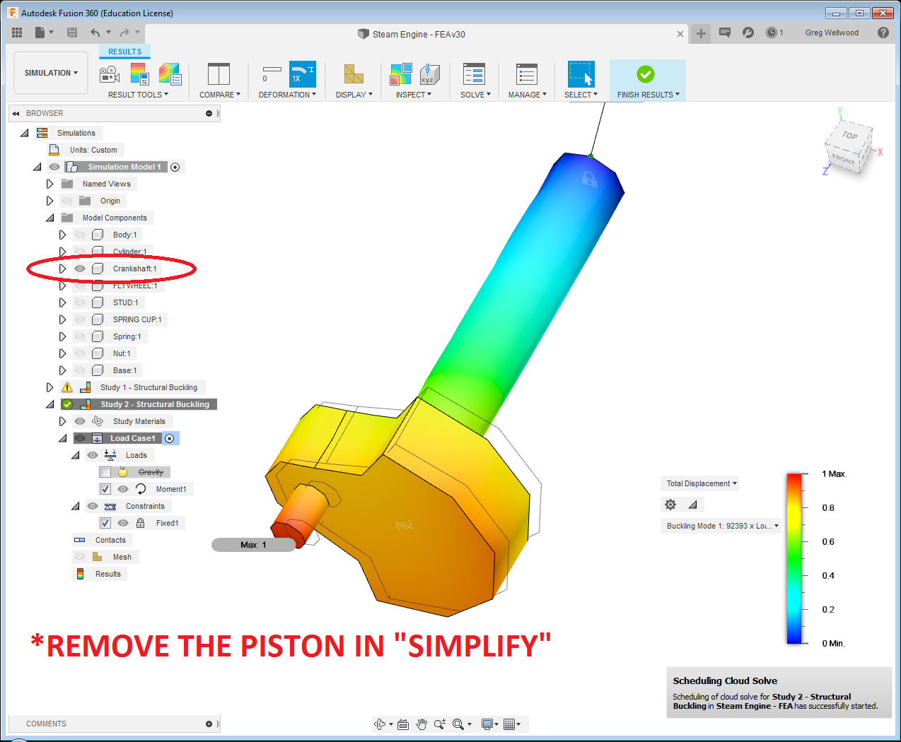
Now take the CRANKSHAFT from the Steam Engine, and find out how much MOMENT FORCE (rotational) it can currently withstand. This will require fixing ONE end, and applying a MOMENT FORCE to the end of the pin. Use a figure of 1. Be sure to make/unmake things visible.
No, I’m not showing you how to do this. Figure it out. You will need to REMOVE the piston by “SIMPLIFY.”
Now find out how much bigger you need to make the CRANKSHAFT for it to withstand 50% MORE MOMENT FORCE (hint: it’s not 50% bigger).