Chassis based on a set of Lotus Seven SII drawings from Prince Race Car Engineering circa 1981, with adapted structural enhancements from Caterham and DSK, and some suspension mount ideas from Fraser (NZ). Reconstructed from some original parts.
This page will become more developed as the project progresses.
THE BUILD TABLE

The build table. 1″ thick 4’x8′ MDF top, 3/4″ thick 7.5″stringers, 5/8″ thick bottom. All screwed, glued and trued.
THE FRAME BEGINS

Do the “top” tubes first, so you can keep the bottom screwed to the build table once it’s assembled.

The top front “X” was done in the wrong tubing diameter.

“X” was cut out, and re-done in 3/4″ instead.

Those front uprights are hell. Compound cuts, and I have a single-plane brain.

Engine bay side diagonals are easy to cut on the milling machine.

Prince plans call for a 1″ space between the end of the engine bay main diagonals and the second upright. This nagged me, and I later changed it.

With a nod to DSK’s triangulation, I altered Lotus’ rear suspension pickup point tubing. This makes more sense to me. Lay out the tubes with masking tape, and it’s easy to get lengths, angles, etc.
Roll bar legs should have gone all the way to the bottom. I forget why I chose to do it this way. I’m sure it made sense at the time. I wouldn’t do it this way again. But by the time I decided this, I was too far into it to go back.

Fishmouths are sexy. Easy to do on my lathe as well.

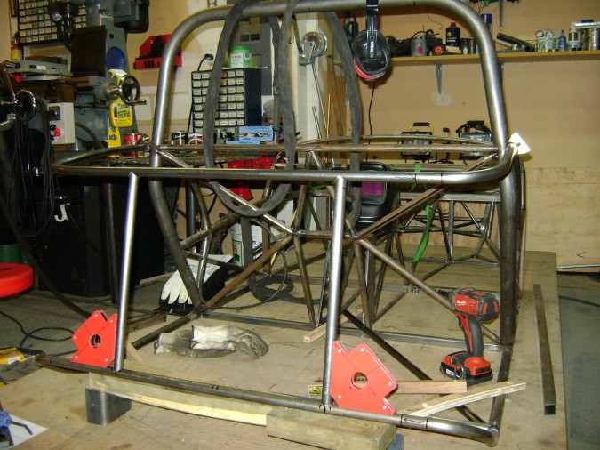
Magnets are great for that extra hand, but they mess up the TIG arc some.

Angled and offset, to different diameters. Sexy.

Mmmmmm.

A bit more triangulation.

That intersection there, will have the suspension pickup in the middle.

I don’t like this fit. Lotus likes all the tube centerlines intersecting. The engine bay diagonals do not intersect.

That’s better.

The seat back bulkhead is a challenge. How to hold all these tubes?

Pretty tube intersections.
THE TRANSMISSION TUNNEL

Working on the transmission tunnel, fitting a 240SX transmission adapted to a Ford Duratec 2.0L. Engine and transmission are offset 1″ to the right. With a 5″ hoop, this gives me about 17.5″ for my seat, 14.5″ for passenger. Passengers don’t matter that much….

Tunnel height meets the rear bulkhead at the same height as the outside tubes.

Driveshaft loop to stay D/Mod legal with slicks.
THE WHEEL ARCHES

Wheel arches next. These were bent around a 12.25″ inside radius wooden die I made. The spring-back brought them to the 14.25″ outside radius the Prince Plans called for. I have another set of plans that call for 14″ outside radius. Will it matter? I’ll find out when it’s too late.

I don’t think the arch adds a whole lot of structural rigidity to the design. Later Caterhams added a diagonal in there to further strengthen this part. I’m not sure it’s needed with the roll bar forming the seat back bulkhead.

The roll bar angles in for appearances, but also enough and at the right place to provide room for hood sticks to pass by. I hope.

The transmission tunnel will get triangulated for more torsional rigidity. The shifter-bay diagonal is not optimal, but probably better than nothing.
It took a bit of figuring for exact placement for the transmission in order to fit the 2.0 Duratec in an S3 size chassis. I think it’s going to work, but it’s also a very tall engine. It could present some challenges.
I’m finding a lot of tube placements are not optimal (suspension pickups, motor mounts, etc.). They are what they are for packaging and assembly, but if you really wanted to do a good job of this, you’d want to clean-slate everything – but then the result would look very different. I think a true chassis would be purpose-built first, and it ends up looking like what it ends up looking like. Trying to keep this very “sevenesque” creates some limitations on what you can do – compromises, if you will.

The front is triangulated in a manner like current Caterhams. I am not putting in the forward tube as per the S3 Cat, but deleting it like the CSR.
I had the chassis, at this point, pretty much ready for final welding. And then I started thinking…
Why did I offset the drivetrain 1″? This makes a 17.5″ seat for me, which is WAY too big. And a 14.5″ seat for the passenger, which is WAY too small.
For a couple of hundred, I can have a new driver’s axle shortened 2″ which would center the pinion, I could put the drivetrain back in the middle, and have two 16″ seats. What the hell indeed.
So….

Cut.
And hours of alteration.

I altered the seat back bulkhead, as I wasn’t happy with the way I was terminating the tunnel. I was having a hard time visualizing skinning it in an aesthetically pleasing manner. The tunnel top should terminate better like this, and be easier to skin.

Drivetrain is back in the center, with original footwell widths (as before).

But I’m going to angle the motor and transmission just slightly right to try and optimize fit, U-Joint longevity be damned.
The next part I tackled was a total PITA.
THE DASH HOOP
No decent drawings on the ‘net. A couple CAD drawings that were deliciously vague. Somewhere I think I read “shape to fit scuttle.” Well, I happen to have the scuttle, but the scuttle gets its shape from assembly – which means “get yourself ready for a wack of trial and error.”
That, and how the heck to you attach a 3/4″ top hoop to the 1″ uprights and cross bar? Fill the voids with Bronze Weld I guess….. but I’m TIG’ing the frame. You can’t weld air.
After a lot of thought, I decided on this:

I drilled the ends of the dash cross bar half way through with a 1″ holesaw, then continued through with a 3/4″ hole saw – offset (not centered) to locate the dash hoop right against the “vertical” dash mount – this should allow some height adjustment before final welding.
Then I shaped the ends a bit so the transition can be a bit smoother:

Next was tackling the dash hoop itself.
I figured, logically, that Lotus would have used a common die to bend the ends, maybe intentionally not taking into account “spring back” with the resultant “bow” of the top a result of the bend. Yeah. I laughed about it later too. The shape cannot be done with a typical die – it needs to be bent the old school way.
Then I took a digitally available online CAD drawing and made a wooden buck according to their drawing. Which might have been on crack, because it didn’t work. But not before I filled a capped tube with sand, and heated it and bent it into an accurate version of the wrong shape.

1st TUBE: close, but not right; 2nd TUBE: trying different things with the remaining tube; 3rd TUBE: capped, packed with sand, bent with heat; My 3/4″ 3.5CLR die; The Wooden Buck of Frustration.
Eventually, I got it right.

And the stupid thing fits. Oh, and the verticals are actually angled inward about 2-1/2° so they are in the same plane as the chassis sides. Which will probably turn out to be a mistake I will discover well after it’s too late to do anything about it.
I decided to do the bottom tubes directly behind the seat in 1″ round:
- I will be using DSK-style four trailing arms and a panhard rod instead of the Lotus’ two trailing arms and an A-frame
- The A-frame is certainly simple, but I don’t think it is ideal – lots of stories of excessive stress breaking the axle housing, and peculiar handling traits. DSK impressed one reviewer with their setup such that they got out and had a look underneath.
- The Panhard will fit best behind the axle. The panhard mounts need to be strong.
- To better strengthen the panhard mounts, diagonals should go from the mounts (rearward longerons and crossbar behind axle) to the transmission tunnel (vs. Lotus’ diagonals from longerons at seat bulkhead to center of rear crossbar).
- Since the cross bar will not be connected in the middle as per Lotus, the tube should be larger to reduce any chance of flexing or fatigue.
Would it have been enough to do in 3/4″? Maybe. But my gut feeling is it would be right on the edge of acceptable. So boo hoo. I changed it.
Then on to the rear curved tubes.
The lower tube was changed slightly from the Prince drawings since it was no longer one piece. I bent the 3/4″ tube in the cast-aluminum die I made previously. The 18ga tube wrinkled in the die, whereas the 16ga practice ones did not. Perhaps a better fitting die is required, or this should be packed with sand and bent with heat. I used it anyway.
The curve of the “kickup” of the bottom tube was tweaked into shape by hand to match a 1:1 section of the Prince drawing.
The downward curve of the top tube was bent by hand to fit a buck I made from a 2×4. It’s a pretty gentle curve.
Next I needed a good transition from the 1″ longerons to the 3/4″ rear tubes. Washers should work.

I dissolved the chrome plating off in Muriatic Acid. You want to be upwind from this. And wear protective gear.

Washer in place

Tacked together

The top will fit like this


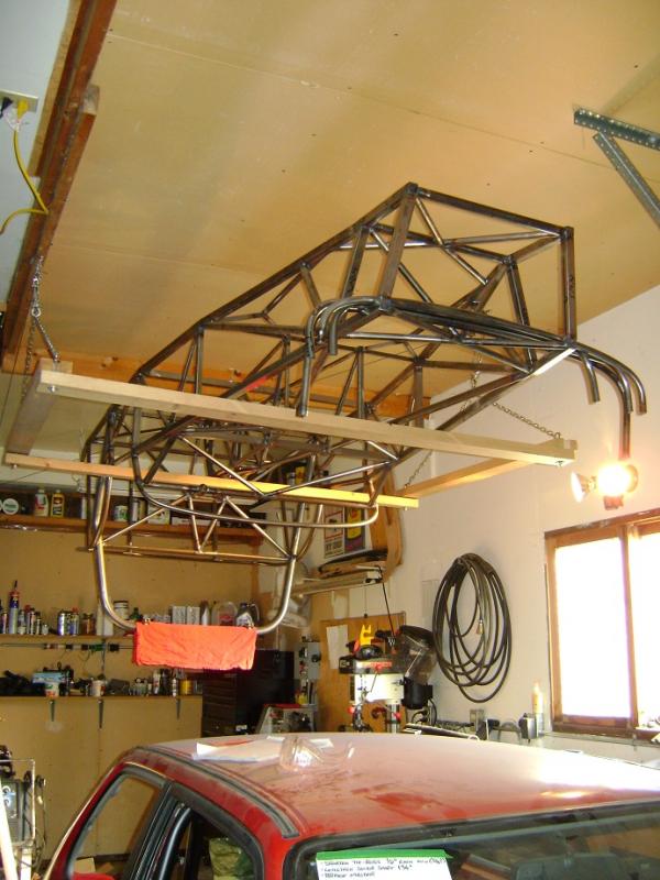
Project is on hold until the Fiendish Firefly (below it) is complete.