Body Chassis Drivetrain |
Electrical Interior MegaSquirt |
First Drive Racing Media Daily Driving |
Basic Chassis
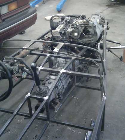
The frame is essentially the same as “The Book,” I moved the scuttle (cowl) back 2″ and the footwell back 2.5″ to more closely copy an original 7 frame proportions. If I were to do build another, I build a true Series 2 Super 7 replica using Lotus dimensions. The “Locost” is too roomy for me, and a lot of the Locost design appears to be “afterthought engineering.” If you study Colin Chapman’s 7, the man is brilliant; nothing serves only one purpose. He is a master of light weight and efficiency. But I digress.
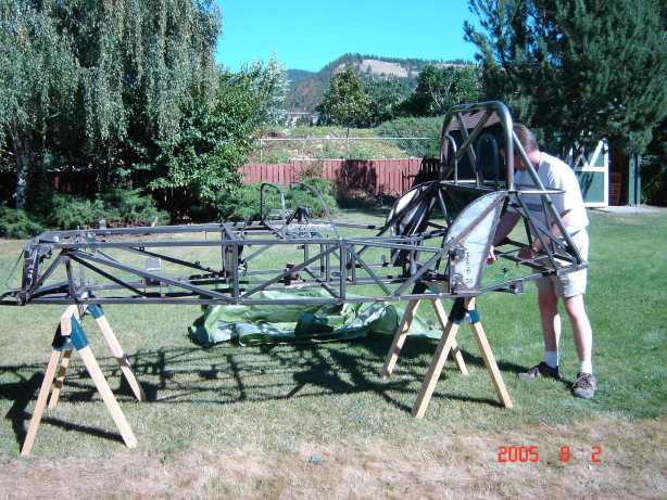
The frame is made from 1″ and 3/4″ 16ga square tube, and 3/4″ 16ga round tube. It was laid out on a 4×8 sheet of 1″ MDF. Tubes were kept in their location by strips of 3/4″ plywood screwed into the MDF. The entire frame was tack welded on this jig.
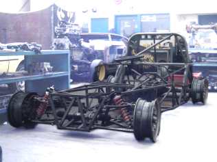
Book chassis – would change the rear for more shock clearance and better “boot” design
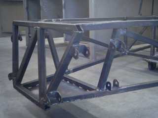
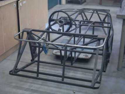
Some Aussie mods done
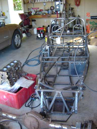
Final details before paint
Frame Alterations
I reinforced the rear suspension mounts since some Locosts have had problems with the rear trailing arm mounts breaking off. I also implemented some improvements (called “Aussie Mods”) to improve torsional rigidity. This includes a pair of tubes welded to a “V” in the front (from the mottom of the “L” tubes to the meeting of “S” and “T”, as well as diagonals from the top of “L” to the bottom of “F”. I also added two tubes from the top of “F” to the motor mounts.
I would have preferred to have the W1 and W2 either removed, or located parallel to X1 and X2. This would make closing the floor of the boot much easier (especially with moved roll bar rear stays (see below)). I would also RU1 and RU2 horizontally out the back, then kick up from Y to meet V. This would appear more “full” from the rear, would provide more axle room (especially for a low Panhard, Mumford, Watts linkage, IRS, etc.) and would be closer to an original.
Drivetrain Location
The rear axle pinion is offset 1″ to the right, and I offset the motor and transmission 3/4″ to the right for more foot room – I can actually fit my feet on two pedals at once!. The oil pan sits 1.5″ below the frame, and is set back until the bellhousing-to-transmission seam is even with the front edge of the footwell.
I designed and built my own pedals, changing the lever ratio on the master cylinder to 6:1 as I did away with the brake booster. Clutch pedal ratio stays the same. Throttle is the original 1:1 ratio. The pedal pads are made adjustable as the seat is not. If I were to do it again, I would make narrower pedals, and squeeze the clutch pedal a bit closer to the brake so I can have a dead pedal – a simple tab to rest my foot on. I would also NOT do a pedal arrangement like I have here, I would have 1st class levers with twin master cylinders mounted above and reversed with a balance bar. I am currently having brake bias issues with Chevette front brakes and Corolla rear brakes.
Engine offset 3/4″
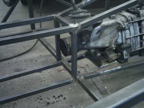
Speedo cable bend is awkward; vertical tubes should have been moved back to act as driveshaft hoop
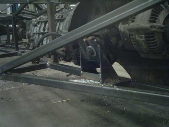
Simple motor mount, engine is 1/2″ below bottom of frame
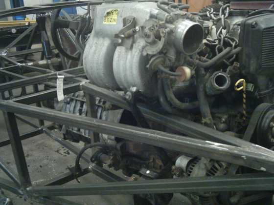
Intake manifold is too tall
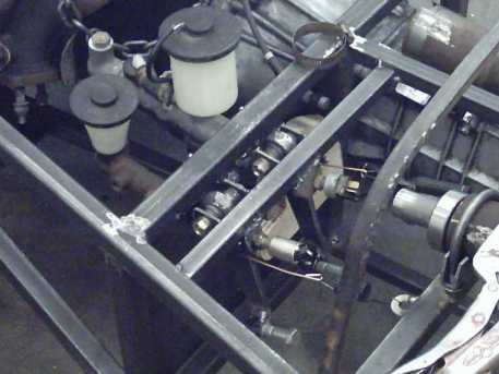
Simple pedals, but no way to remove or service them!
Scuttle
The scuttle took me some thinking to figure out. The book seems rather spartan in the “how to” area of this. I ended up relieving and bending 1/2″ angle iron around a plywood jig to make the curve for the firewall and dashboard. The cuts were re-welded and the two pieces welded to the frame. A skin of aluminum wraps over the scuttle and is clamped to the frame on the top of the side rails. If I were to do this again, I would more closely emulate the original Lotus with a single tube hoop as the dash/scuttle mount. Again, I would probably do a true replica next time.
Roll Bar
Liam Burr of Suzuki Swift fame bent up a roll bar for me – 1.75″ ERW for the main hoop and 1.5″ ERW for the stays and removeable Petty Bar. I used a program called “WinMiter” to fish mouth the tubing – excellent program!
Headrests were added to the frame for a bit more support and safety. They were upholstered in the same material that the seats will be, and then later removed when I shortened the “flagship” roll bar 3-1/2″ and used the diagonal as a headrest. The roll bar height is 15-1/2″ above the top tube of the rear bulkhead, and looks very good now. Not “hit low-flying birds, look at that freaking ladder on the back of that car” tall.
I would have preferred to have the rear roll bar tubes connect to the rear hoop of the “boot,” despite the glaring lack of structural strength. This would have made the boot more accessible, and improved the car’s lines (much like the original).
Painting
The frame was painted with two coats of Rust Bullet which I ordered from their Canadian distributer: Caswell Coatings. I sprayed the paint in my backyard, with a Princess Auto cheap-o spray gun, a charcoal-can filter mask and two pairs of eye protection (and I still got overspray on my glasses). Rust Bullet really prefers rusty metal – it comes off clean new metal very easily. you might want to leave the frame outside for a bit before you paint. “Metal Etch” (Phosphoric Acid) is popular with the POR-15 crowd, and might be worth trying.
Prepping for paint
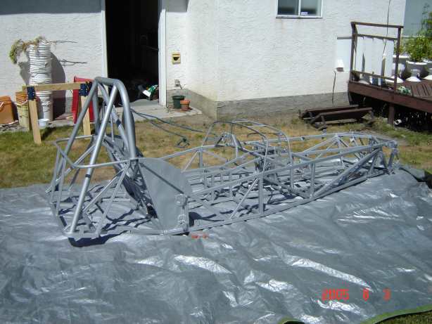
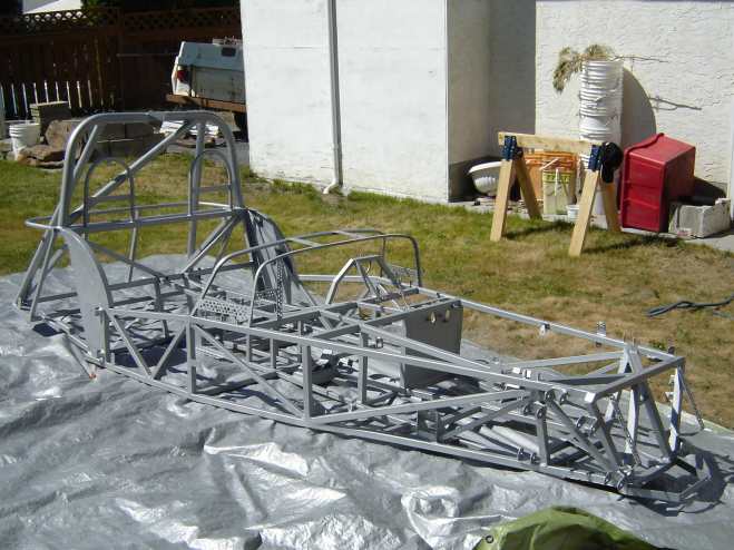
Two coats of Rust Bullet
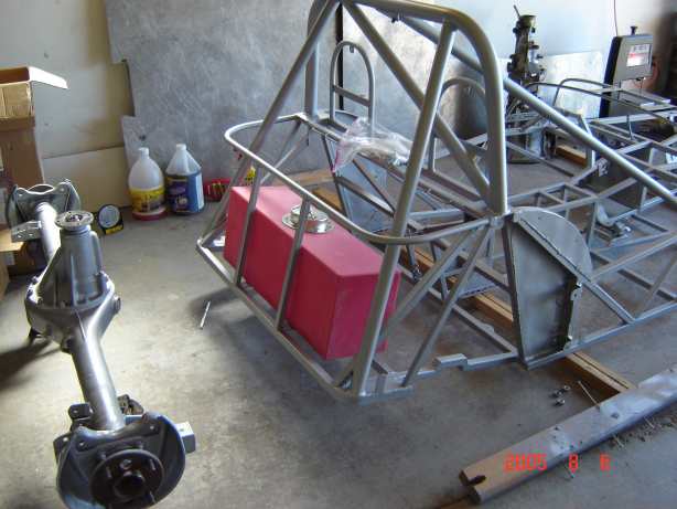
eBay fuel tank