[ Start ] [ A/C ] [ Bodywork ] [ Bushings ] [ C-Notching ] [ De-Arced Leafs] [ Driveshaft] [ Drivetrain] [ Exhaust ] [ Lowered ] [ Quirks ] [ Wipers ]
I’m getting old.
My sweetie’s Sunfire has air conditioning. I like having air conditioning in my vehicles. The truck gets brutal hot in the summer, and the wind noise with all the windows open (not cooling you down, I might add) is brutal – 102dB measured at 100km/h. That’s hearing damage zone.
So, I scoffed all the parts to install A/C from both Kelowna Pick-N-Pull and Vernon Auto Wreckers.
If you can get all the parts from ONE vehicle, that would be best. From an R134a vehicle, even besterest. If you have the KA24, get the parts from a KA24 vehicle.
Things you will need to get, most of which can be used:
1. Compressor
2. Compressor bracket with belt tension idler
3. Pressure line to Condenser (and support bracket)
4. Condenser
5. Drier (buy new, such as Four Seasons #33582) & Dual Pressure Switch
6. Hard line from Drier to Evaporator
7. Evaporator and housing (Buy a new Expansion Valve, such as Four Seasons #38637)
8. Suction line to Compressor
9. A/C Relay #1 (mounted on RH inner fender – closest to firewall)
10. A/C Relay #2 (mounted in fuse box – middle)
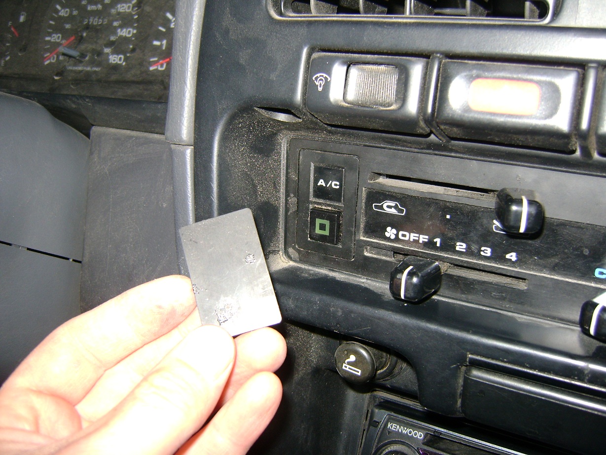
11. A/C Switch on dash
12. Evaporator drain hose and grommet
13. Evaporator firewall grommet
14. New O-Rings
15. (not shown) A/C belt – Dayco #17340 fit my truck

Luckily, Nissan really planned this out, and installing it all is really easy and all the wiring is already there. The final filling needs to be done with specialized equipment, so you may need to farm that out.
This is merely the order I installed the parts:

Pull the grill off and remove the center support. The Condenser fits into existing holes in the lower panel.
Drier hard line is supposed to be stuffed through the round hole in the upper left, where the wiring connection is shown below. I, however, stuffed it through the lower hole because I thought that’s where I got it from (below the overflow bottle). My bad. Either way, use 3/8″ rubber insulated P-Clips to secure to the inner fender.

Dual Pressure Switch wiring is tucked behind the headlight, taped out of the way.

Drier attachment. Wires should actually go behind bulkhead. (This picture was taken after the system was fully assembled and charged up.) ALSO the solid line should enter the engine bay through the TOP hole, not the bottom one. Stupid me. Works though.
This is where I discovered that the R134a Pathfinder evaporator I had acquired did not match the R12 lines I got from a Hardbody. Installing the Evaporator had to wait until another trip into Vernon….

Compressor Bracket is attached to existing bosses in the engine block.

Compressor is attached to bracket (hard lines are installed in this picture).

Shot from the bottom. Removing the splash pan makes this easier.

Existing A/C Compressor wire is here….

…. but it needs to look like THIS to connect to the R12 pump I have. Solder & heat shrink tubing.

One relay connection is tucked under the wiring harness here.

The relay is attached beside an existing relay. I used a 1/4-20 RivNut and bolt.
Picked up the correct evaporator. No visible difference other than the suction end.

Remove all the clips from the Evaporator housing, carefully separate the two halves, and carefully remove the old Expansion Valve. You could gamble on using the old one, but you’re in there anyway – it’s easy to change it now.

The original Expansion Valve was wrapped in some sort of foam tape wrap stuff that I couldn’t find when I needed it. I ended up using some pipe wrap from Home Depot, with some tape to help secure it. The point of it is so that the Expansion Valve ONLY sees temperature from the tube it’s clamped to, not ambient air. This should work.

Remove the glove box door and rear panel. In mine, the ECU had been relocated from under the seat to the rear panel – you won’t see all that nasty wiring on yours.

Notice the extra connector taped to the blower resistor wires. It plugs into the top of the Evaporator housing.
3 screws and the whole empty tube comes right out.

Poke out these plugs. These are where the A/C goes. The drain hole is about 3? to the left of my baby finger.
Install the evaporator housing into the vehicle.

A different plug seals the lines through the firewall. It uses the same hardware though.

Dash push button wiring is just hanging right behind this panel. Here it is hooked up to the switch. Evaporator is already installed. 3 bolts, two plugs. Easy.

Push button just snaps in place once you remove the blanking cover. Snake the wires around to connect as shown previously. You will need to remove the center trim piece, and pop the heater control ends and bezel off to get at all of this.

Had to chop a hole in the rear panel and deform the glove box a bit to clear the ECU and everything. Again, this is abnormal – yours won’t be like this. I’m sure there is a tidier approach, however, but I’ll worry about that later. I don’t spend a lot of time in the glove box.

This relay isn’t listed in the FSM wiring diagram I have, but it is mentioned in the pictures. Or maybe I mis-read it. You will need it. Plugs right in. I used one of the two relays I stole from under the hood of the Pathfinder.

Evaporator to Compressor line attaches easily to existing plastic plugs in the firewall.
Next, the system is fully evacuated (using vacuum to boil out any moisture) and charging with R134a and some sort of ester-based oil……

High-pressure retrofit fitting attached.