Start – 1 – 2 – 3 – 4 – 5 – 6 – 7 – 8 – 9 – 10 – 11 – 12 – 13
In which I make some refinements, take it to autocross, and blow up the motor.
Hmmmm. Page 12. Apparently this is a 12-step program.
Must mean I’m nearly done.
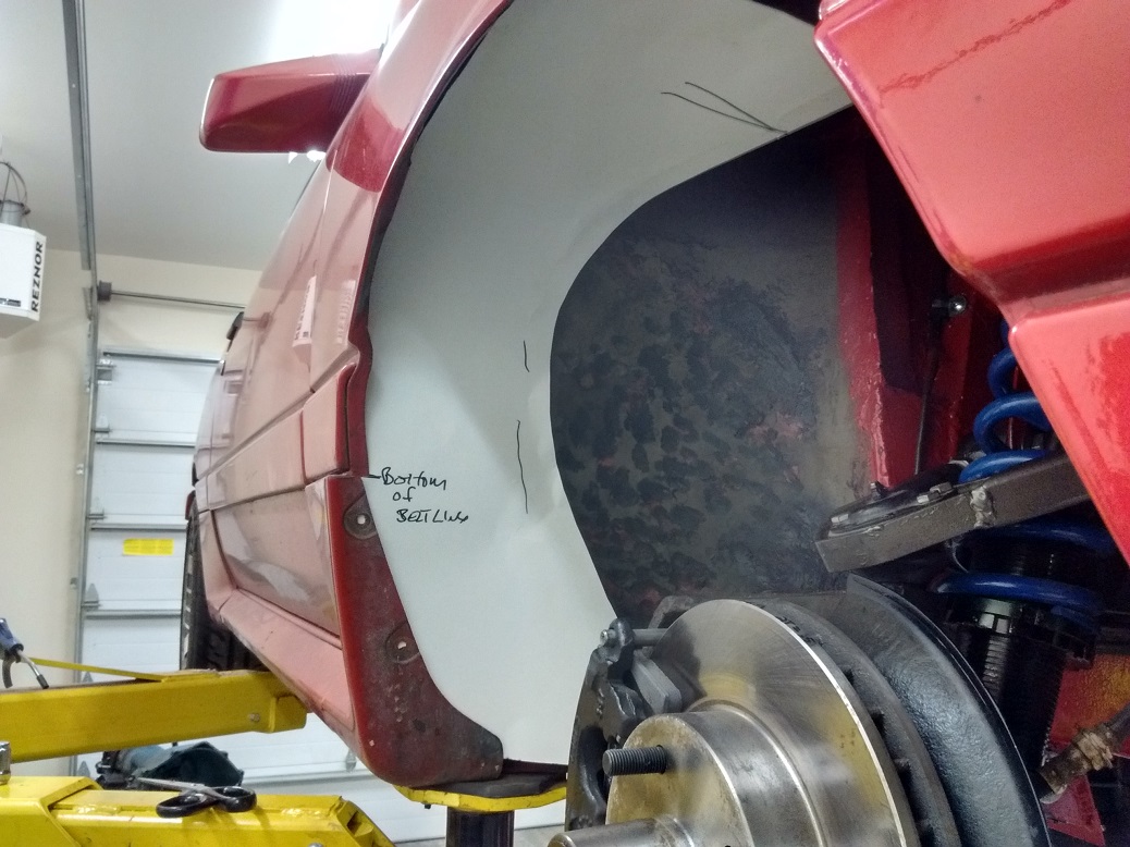
I rolled the fenders edges to fit the Firebird wheels properly, but that made the original inner fender no longer fit. I tried to modify them to fit, but ruined them, because I got skillz.
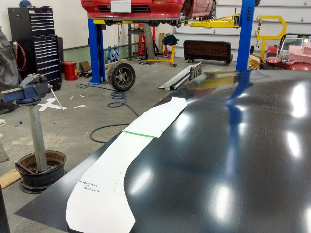
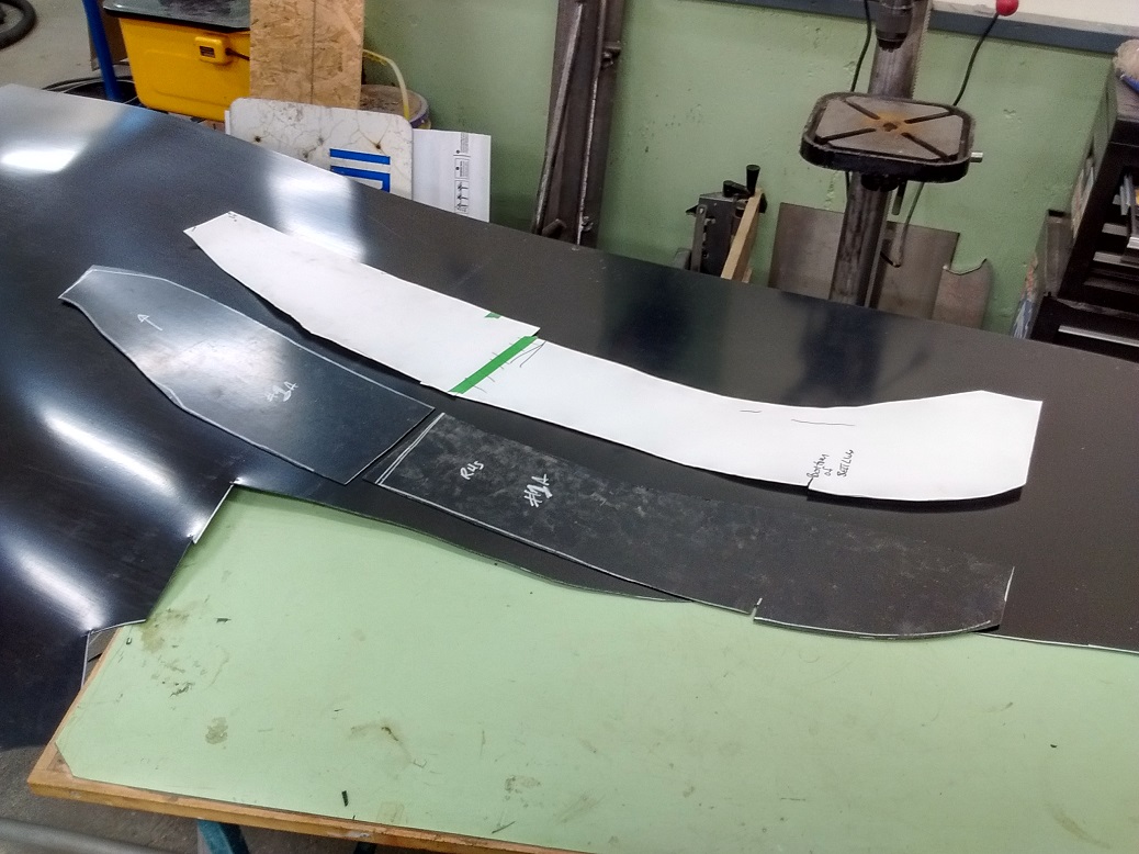
So I bought a sheet of 1/16″ ABS plastic, and started fabricating new inner fender liners by first making a pattern out of card stock.
(January 2018)
Once the template was finished and I was content with the fit, I traced it onto the ABS, and cut it out with tin snips.
Then trial fit, discover just how badly I made the template, and then I cut up and modified the now plastic version of the pattern.
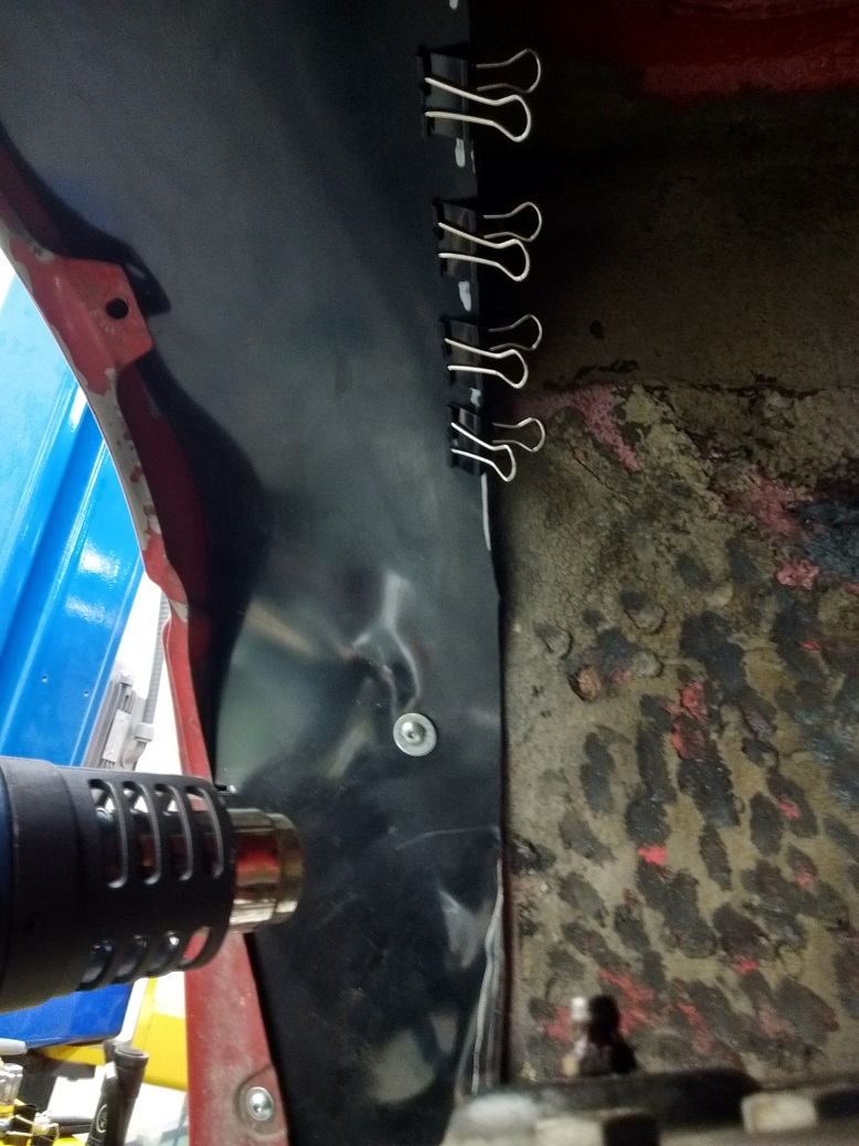
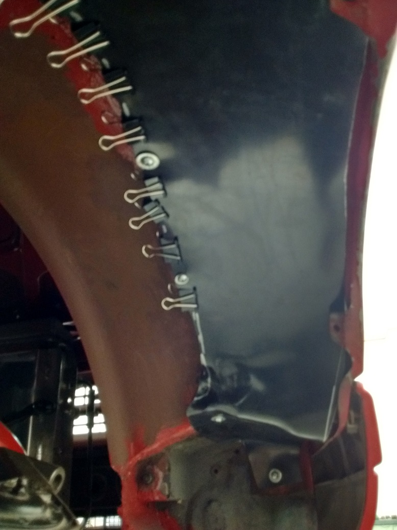
Spring clips help hold it in place while I trimmed, shaped, and held it in.
The other side went a lot slicker, and these inner fenders look worse in pictures than they do in person.
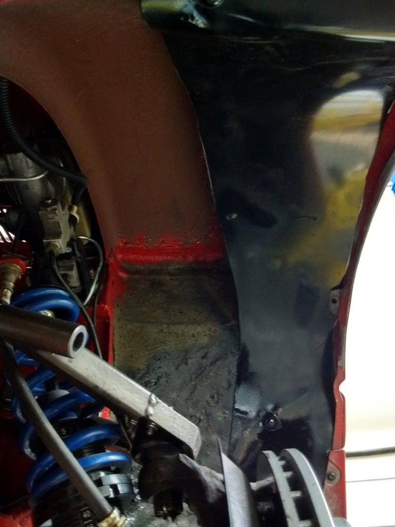
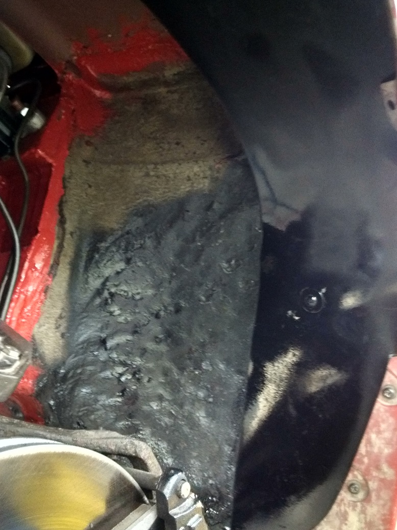
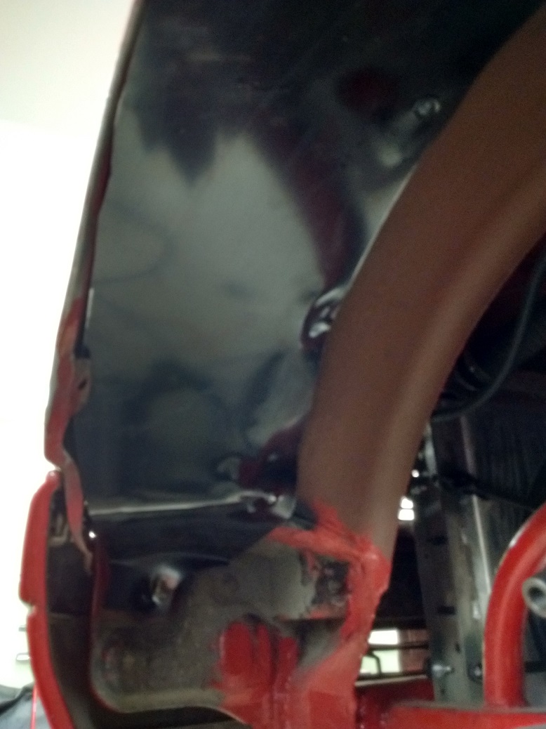
Not as pretty as I’d like, but their main intent is to keep the rocks and water out of the inside of the fender, and out of the door hinges. This’ll do.
The back brakes were always “iffy” all last fall, despite copious bleeding.
I had bought a new master from the local auto parts store, but while it bench bled really nice, it didn’t fit the pedal pin very well, then the snap ring popped out of the back, and it leaked out the back as well. I was not impressed, and I took it back.
I recently ordered a rebuild kit for the master, off eBay with free shipping. How could I go wrong?
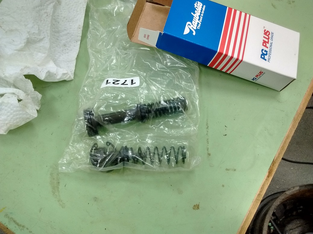
I’ll tell you how – by not researching enough to discover that while all the kits you can get say they are for rear “disc” brakes, the one for rear drums (which I have) is actually the rear disc “performance brakes” master. Which, obviously, is not the one I ordered.
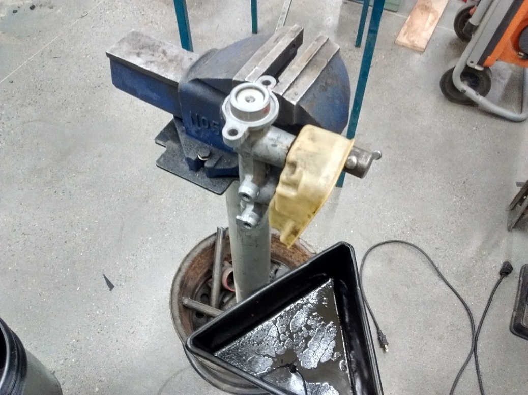
I found this out AFTER I removed the master:
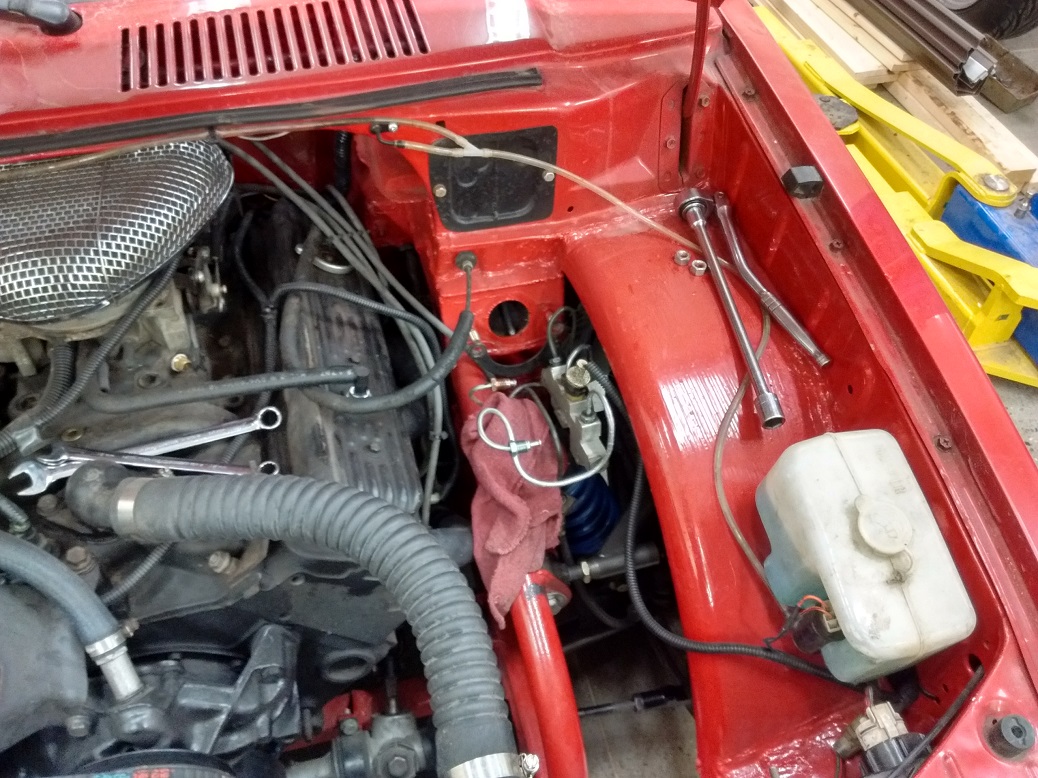
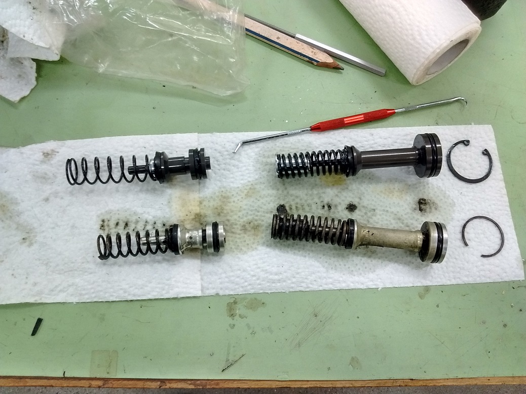
Drained it and disassembled it:
And took the kit out of the bag:
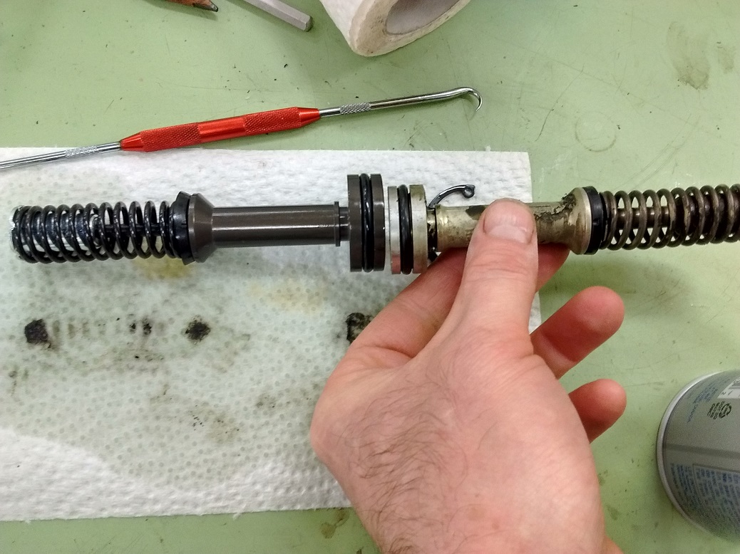
So…. it sits until I get another master. New. For $8 more than a kit. This time ordered from Rock Auto which actually ships quite quickly AND IS CHEAPER EVEN WITH SHIPPING, than my local suppliers.
In more successful news…..
I DID get the right outer tie-rod ends:
I’m using S10 spindles and a Chevette rack. In building the car, I shortened the inner tie-rods as much as I could, and shortened the outer tie rods and much as I could. This allowed zero toe with zero room for adjustment. It worked.
Until I did my messing around with wheel placement, which ultimately moved the spindles forward and gave me improved dynamic Ackerman (yay!). Except this meant I had less than 14mm thread engagement on a 14mm thread (boo!).
So I ordered new Chevette outer tie rods for dirt cheap off Rock Auto, only to discover once they got here that I wasn’t using Chevette outer tie rods (ok, so there is some fail). Luckily, MOOG has a sweet outer-tie-rod-finder-out-inator. Turns out I was using outers from a ’93 Camaro. So, either I knew this going in and put Camaro ends on the Rack as I walked out of Pick-N-Pull, or I suffered some head-trauma that didn’t result in a Wankel or a Flux Capacitor. I seriously don’t remember, and I didn’t write anything down.
At any rate, I ordered some cheap Camaro tie rod ends from Rock Auto, and tonight I trimmed them down only enough to get zero toe.
Was hoping on getting insurance this week, but I’m waiting for brakes. Again.
I guess I could do other things. Like backup lights. And a neutral safety switch.
Been driving the Firefly every day for a while.
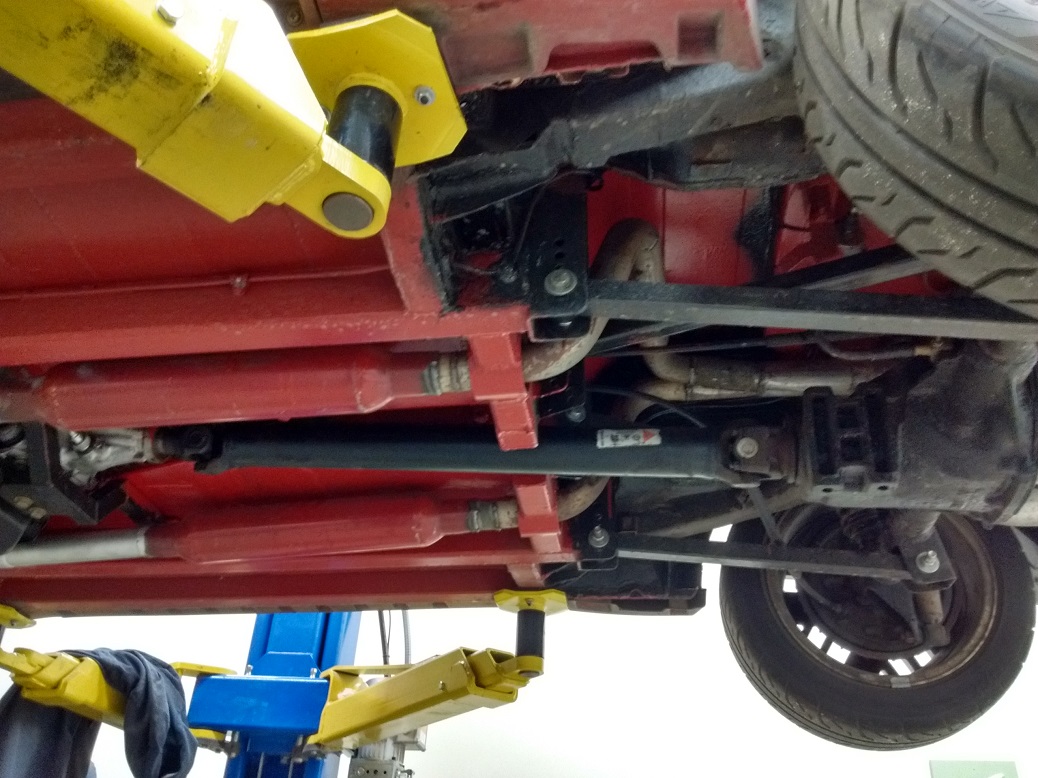
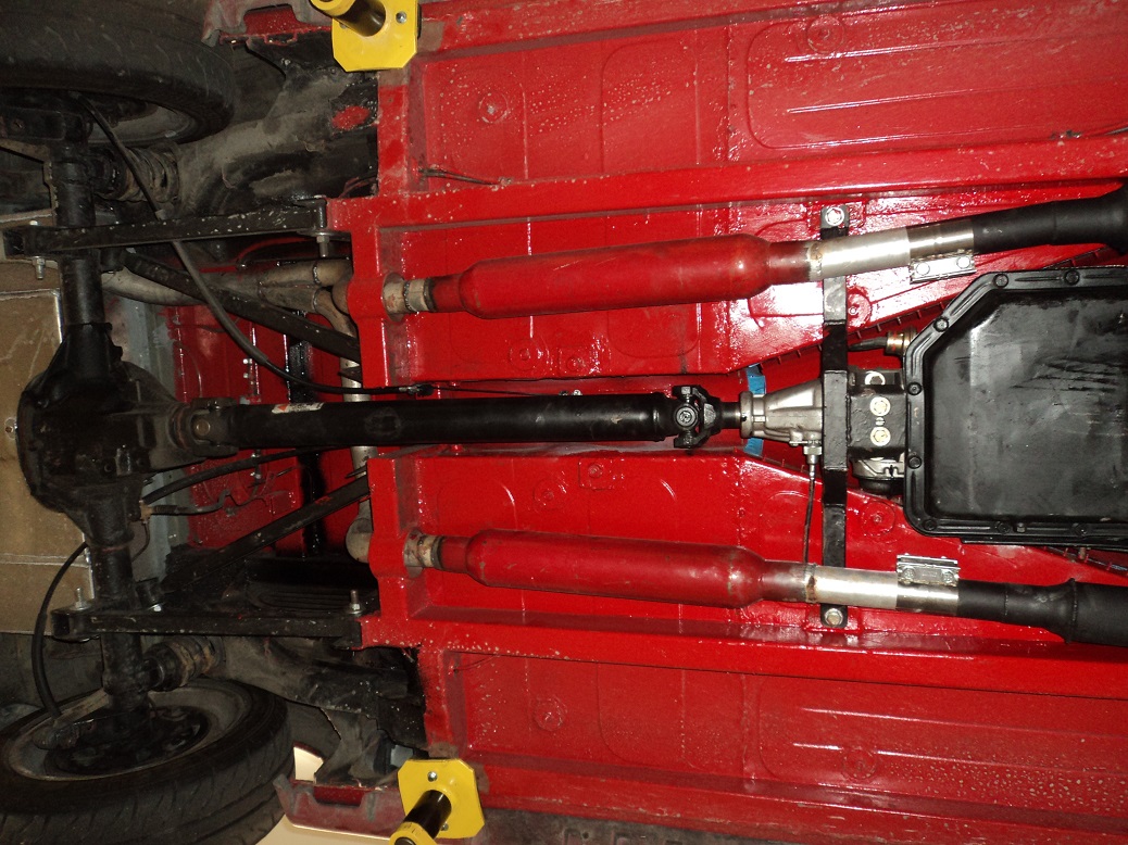
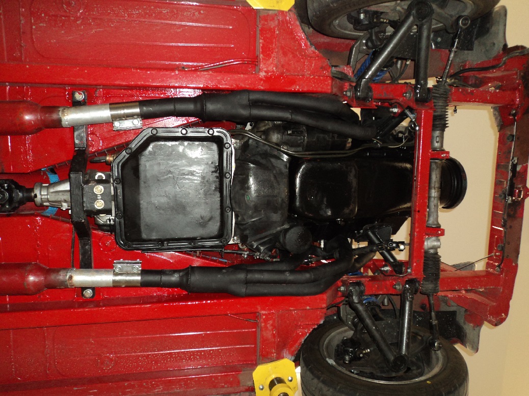
I put it up on the hoist today to change the pinion angle, as I suspect that might be causing a vibration.
Internet lore suggests making the pinion angle match that of the transmission. Which makes sense. Until you build something that doesn’t make sense.
Currently, the trans points down -4.5°, the driveshaft points up 1.1°, and the pinion points up 3.2°. I set the pinion less than the trans to account for bushings. Theoretically, this should be fine.
Except the working angle of the front u-joint is 3.4°, which is a bit on the high side (the trans-to-driveshaft angles are like “v” – apparently you want 3° or less).
And the working angle of the rear u-joint is 4.3°, which is excessive (the driveshaft-to-pinion angles are like ^ (upsidedown V) )
I did some researching, and playing around, and apparently you really don’t want angles of an upsidedown V at the pinion, as the angle will get even worse in deflection or load. Which means my 4.3° working angle will be even worse.
So I changed the pinion to (up) 1.5°, which made the driveshaft 0°, giving a working angle of 1.5° to start. This is not bad. We’ll see what difference this makes.
Last fall I had exorbitant levels of wheel spin. Over winter I raised the front location of the lower 4-link trailing arms, and I -think- I lowered the front upper arm location as well.
This (plus new and sticky tires, plus a limited slip) improved traction considerably. But, I could use more.
Because this is a triangulated 4-link, the upper arms locate the back axle laterally as well as set the rear roll center. The instant center can then only be set by the angle of the lower arms. I drew everything I had up in CAD and found that I am really close to the “neutral line” of no squat and no lift, just erring on the side of squat. If I raise the lower arm front location more, the instant center shortens dramatically but the instant center will cross up into the “lift” zone of 4-link love. This could be good. If I raise both trailing arm forward mounts, the instant center will be a really good length and a really good location, but the roll center starts to get high. Tough to find the balance between a corner-carver and a drag car. Master of Neither.
Today I went from a pinion angle of nose-up 1.5° to now nose-down 1.5°. This also made the driveshaft now 0.2° down, producing a working angle at the rear u-joint of 1.3° which is very good. I did not check the front (though I guess mathematically it would be 4.3°).
I also re-centered the axle because apparently I was drunk when I changed things last. I am also now out of the pinion adjustment I put into the upper arms.
Took it for a rip out on the highway, and it seems to vibrate a LOT less. I’ll know more on my morning commute (no stereo but glasspacks; I have lots of time to think).
ALSO:
Whilst I was making changes over Christmas, I had pulled the TH350 governor and chopped off a fair bit of weight. The same amount I cut off the governor in my ’77 Silverado. Only now that it’s back on the road, it made the transmission was shift WAY after the poor 305 was finished making power. Like, WAY past.
So, I yoinked an un-molested governor from yet another TH350 I had, and plunked it in there. Shifts nicer now.
ALSO:
Mucked with the shifter adjustment so that D is actually D, not half-way between Neutral and Drive.
Interestingly, the 305 didn’t like running such a high RPM when I mucked with the governor. Death came a knocking.
I’ve started gathering parts for a 350.
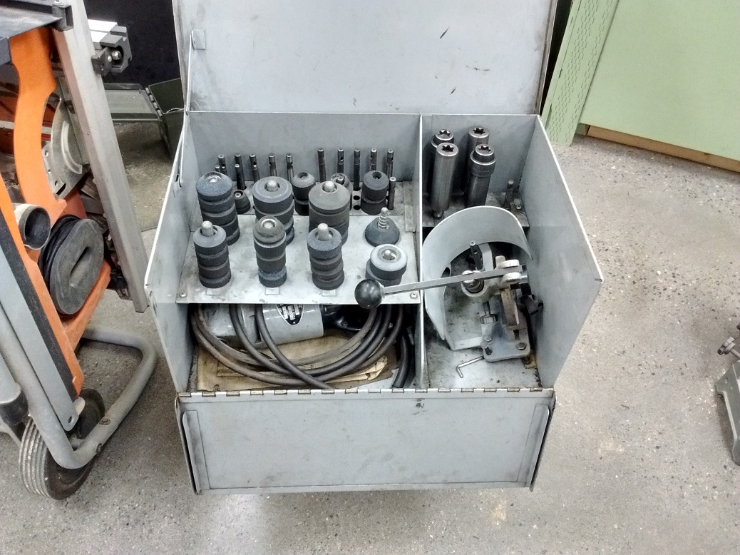
I took the old “882” heads that originally came with The Crusty Chevy, ground the valves, back-cut the valves, knurled and reamed the guides, and did a 3-angle valve job on the seats.
Porting is next.
It’s nice that I have all this engine-rebuilding stuff I can borrow from work 🙂
“882” heads are #10 on the Small Block Chevy Best Cylinder Head list. Yep – the WORST of the BEST. You can see in this picture, even from far away, just how crappy these heads flow:
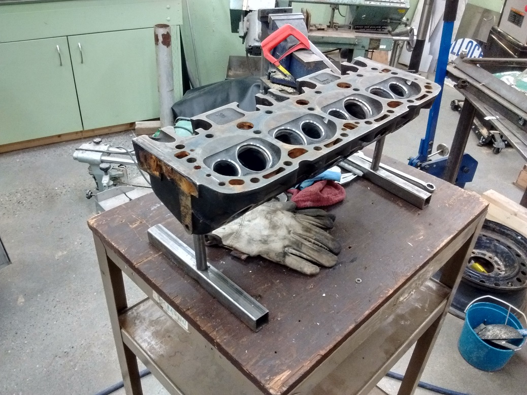
That will all be fixed.
I’m also trying to pick a cam – I think it will be a Comp Cam 262 of some sort. Good idle, good street manners, but more power everywhere.
I ordered a Lunati 10120701 (60101) cam for my 4-bolt 350 block.
213°/219° @0.050″ and 0.454″/0.468″ on a 112°ICL. Should be a sweet streetable cam.
Parts might be here by the end of the week.
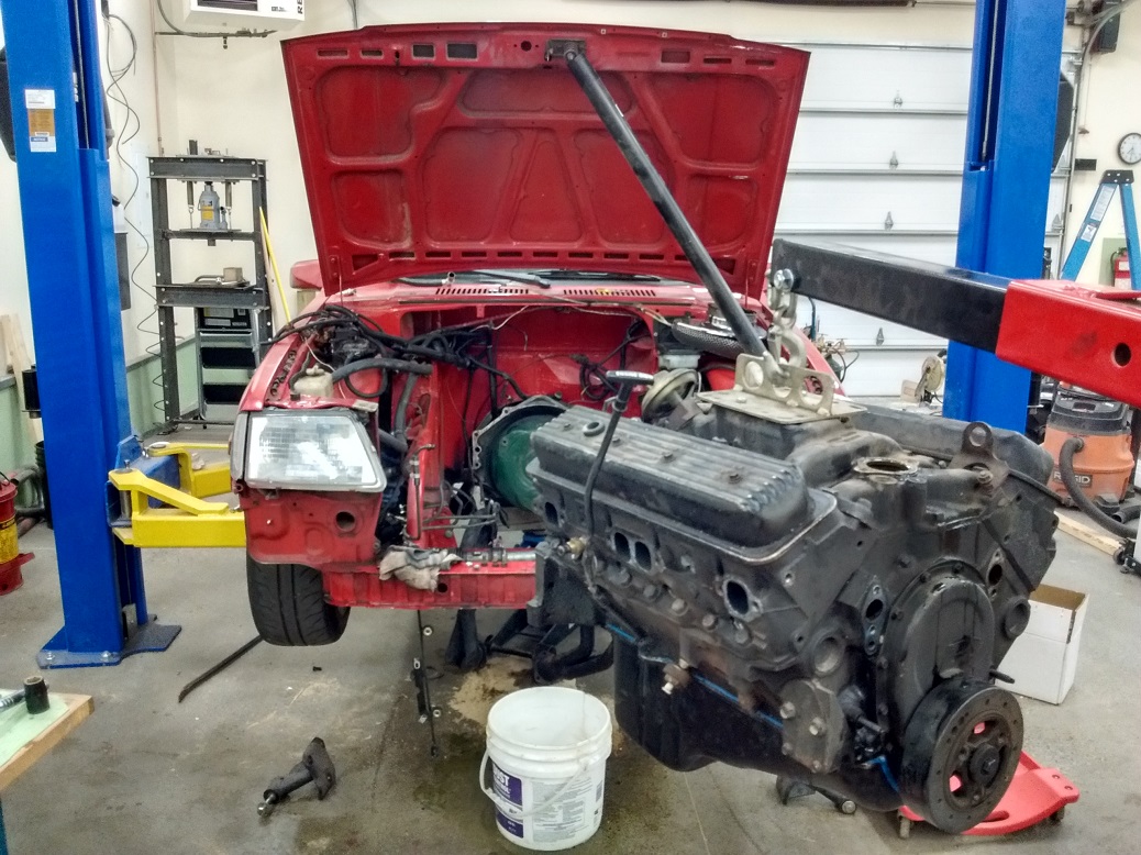
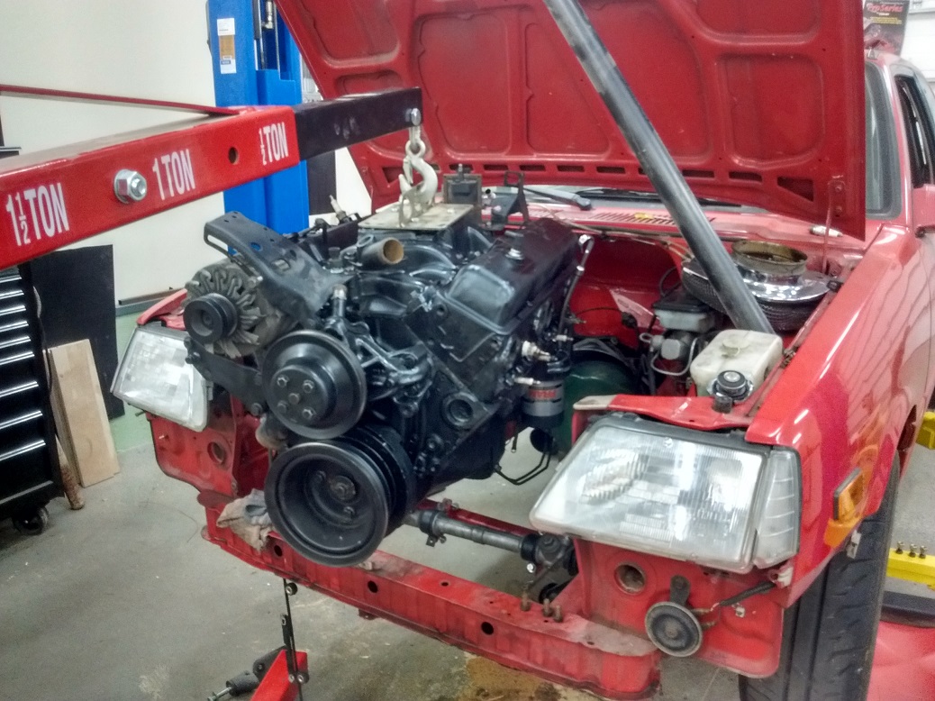
Just need to yoink the engine/trans bolts, and it should come right out.
Started porting the 882 heads.
Out with the sparkly-oil ticking-sound 170hp L03 305 goodness:

And then I ported the 882 heads some more until my hands went numb.
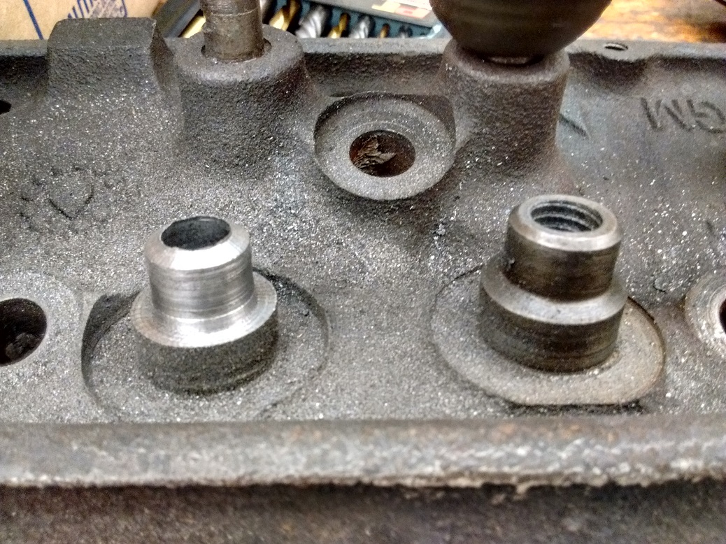
I fabricated a valve-guide boss cutter so I could run modern 0.530″ valve seals. Then: why not shorten the guides so I can run more lift? Boom! I can now run about 0.620″ lift. Not that I am, I just can.
Junk head practice example:
I had a decent 350 4-bolt block (3970010), original bore (no ring ridge), and original crank, flat-top pistons. The crank and rods plastigaged to 0.003″ clearance, so I ordered some 0.001″ undersized bearings to put it back in spec.
The engine went all back together at the school, and (as of this writing) is sitting on the engine test stand waiting for break-in.
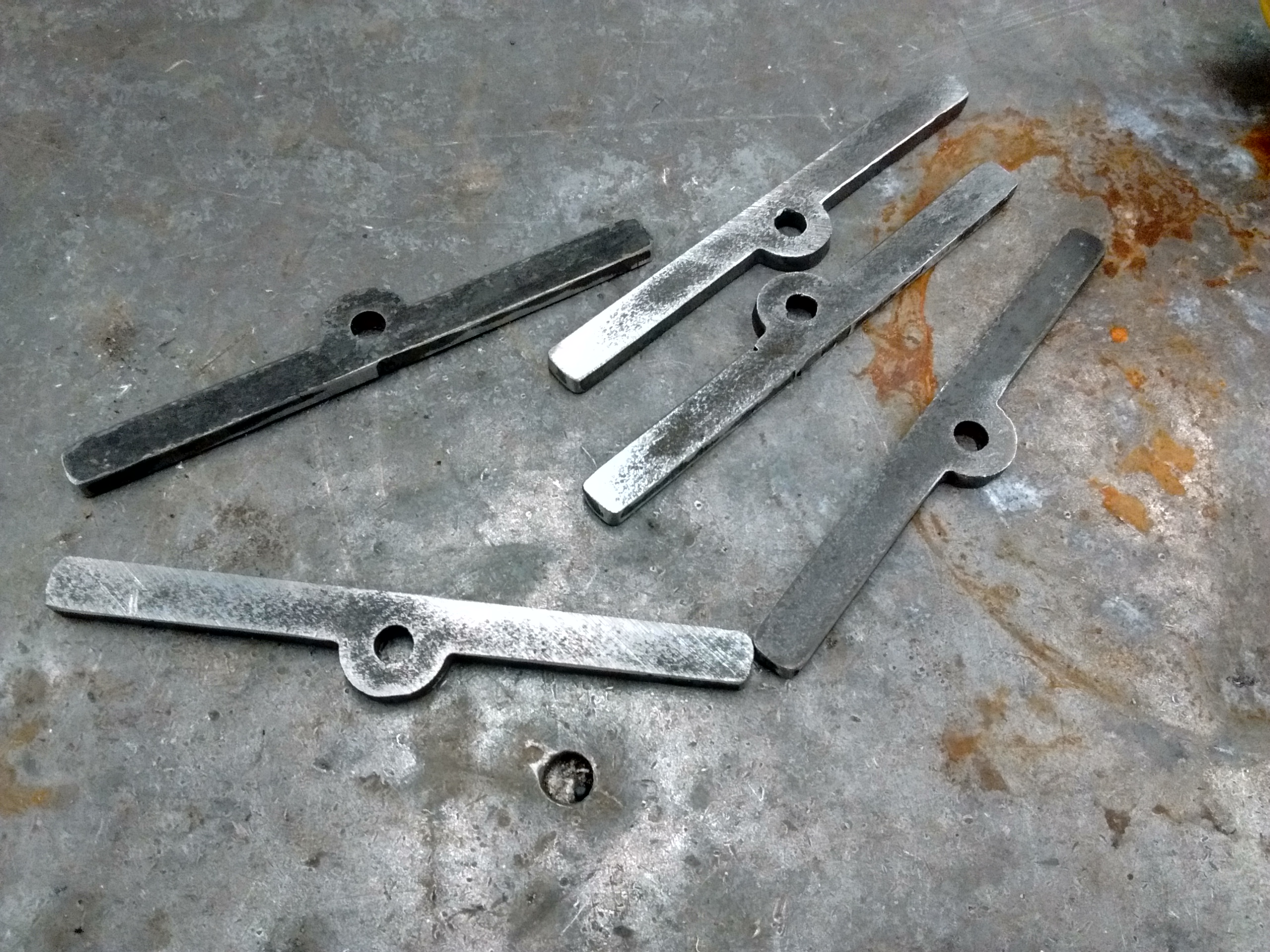
I didn’t want to pay what they were asking for valve cover bolt spreaders, so I drew these up in Fusion 360 and cut them on the school’s Baileigh PT22 plasma table. My first CNC project:
Also got the engine running on our test stand. I still have an oil leak up front to fix (Speedi-Sleeve? Nope – it was a tweak in the timing cover – fixed.).
Turns out you can’t actually bore a TBI intake out to fit the 2″ Big Block unit. You hit the water jacket. Good thing I have two more intakes.
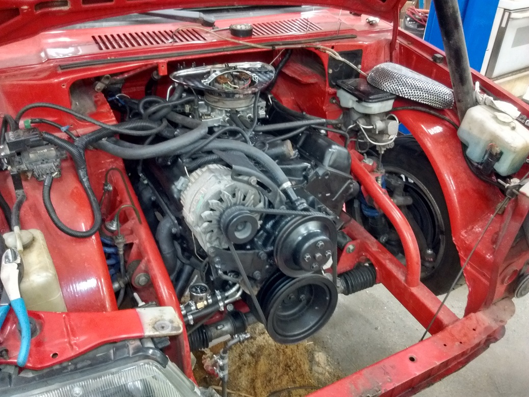
In with the new.
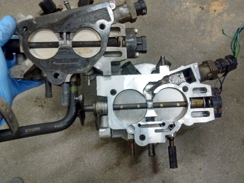
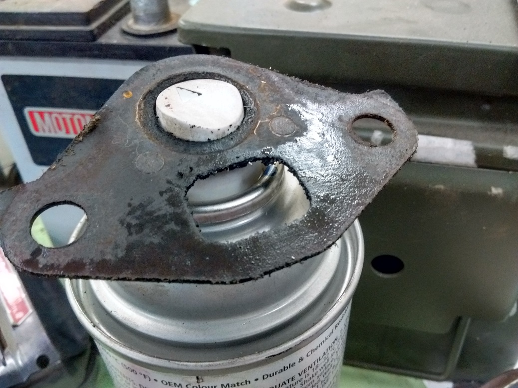
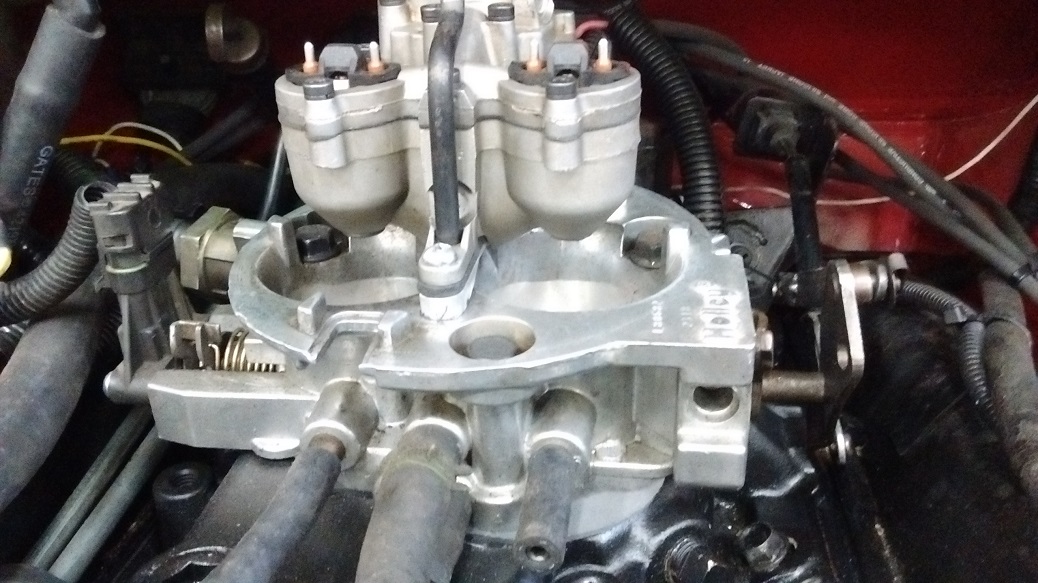
The EGR got a block-off plate, and the intake got opened up to fit the Holley big-bore TBI unit. I frankensteined a factory GM injector pod onto it.
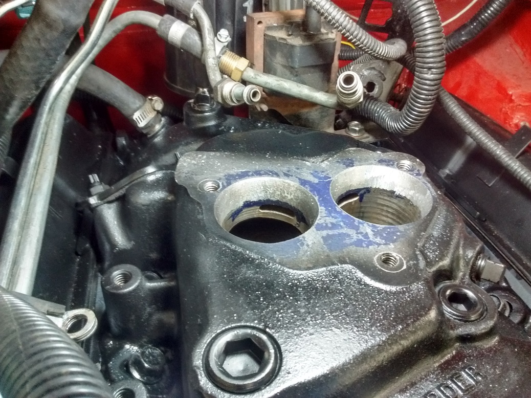
Notice the size difference between the two.
So far I have the fuel system and sensors all hooked up. Needed to take a break to get refreshed.
Today: Remove collector flanges, weld collector to header in preparation for band clamps. Install headers. 3hrs.
(July 2018)
Still have to install plugs and wires. That’s another 2 hours.
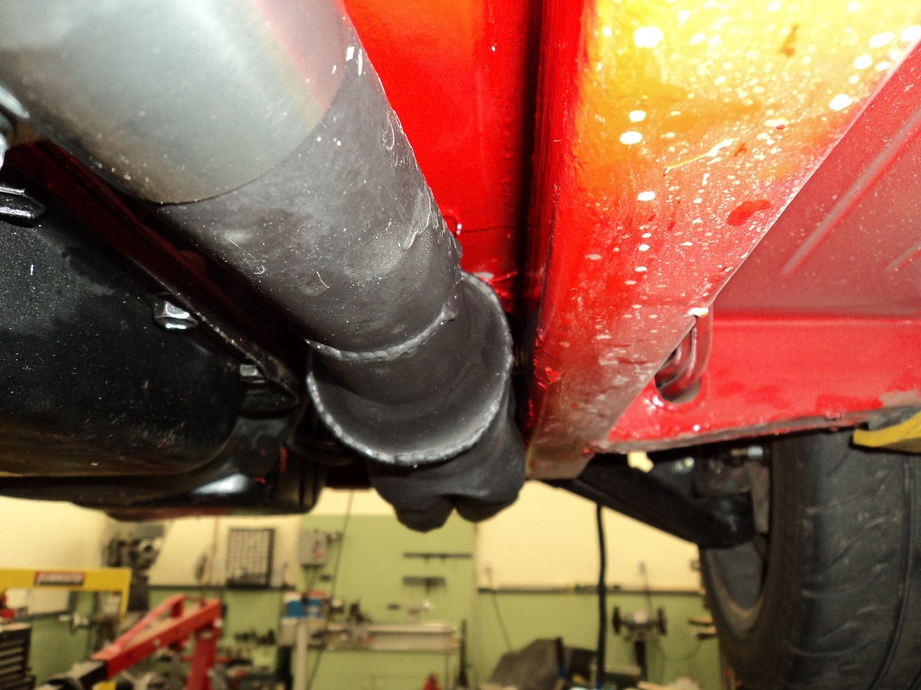
I cut off the header collectors, and welded them onto the header. I switched to band clamps, since clearance is a premium.
Got it running, but I’m running into issues. Runs fine on open loop, but once it gets into closed loop, the O2 sees huge rich, the ECU pulls all the fuel, and I get lean surge. I chased some potential vacuum leaks, but I haven’t found the cause yet.
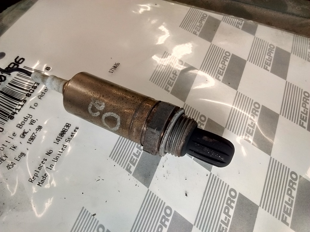
Sooty O2 sensor. Probably original. I bought a new one just to rule it out.
Evidence of my WD40 hosing to find a leak. New gasket fixed that.
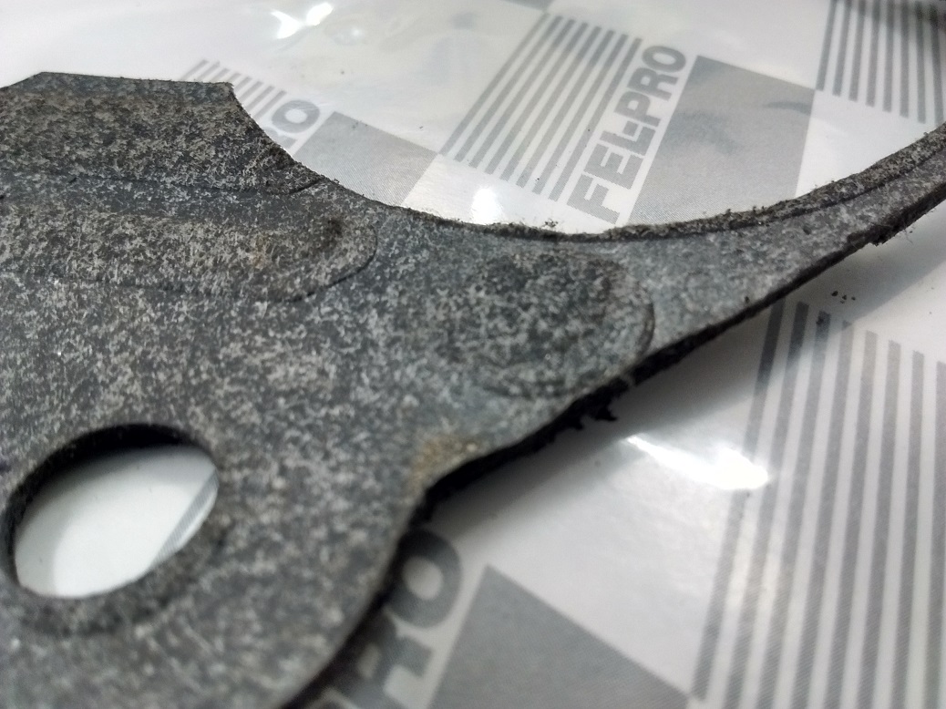
Small block TBI gasket doesn’t fit the Holley big-bore base well. I bought a 454 gasket, which is larger where it needs to be.
None of this improved anything. Last night I went through the 1988 5.0L TBI tune I got off the net, went through every scalar and every table, and compared them to the original factory tune pulled off the original chip from the running 5.0L. There were some significant differences, especially in IAC (Idle Air Control). There were a lot of subtle other differences, but I matched everything from the factory tune, with the exception of -my- Spark Table, a different Injector Constant, disabled EGR, and removed potential trouble codes.
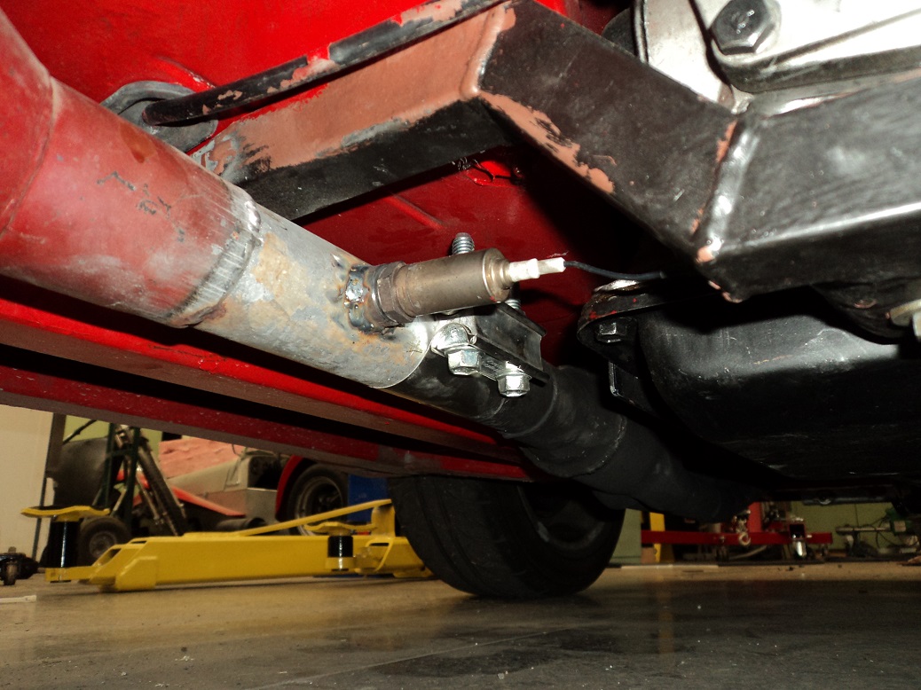
Also, I machined an O2 bung and welded it into a header collector, just removing the possibility that the O2 I was using was too close, or getting a poor signal. I ran a long wire up to where the original (but now new) O2 sensor is, so I can change back and forth if things went south.
Woah! OMG LOL WTF TGIF CIBC TTFN ESPN TSN TMO! This beast is WAY better!!!
O2 sits at a pretty decent 0.447 until it’s active, and it actually responds! Mind you, it’s not heated and it took a while until it was warm, but wow it is so much better.
Clearly, the next step is to hook up the Wideband and do some WOT testing. Clearly. For Science.
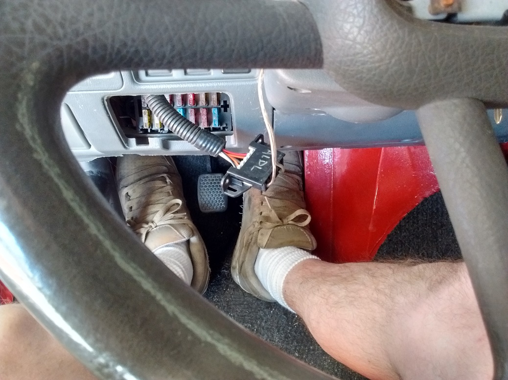
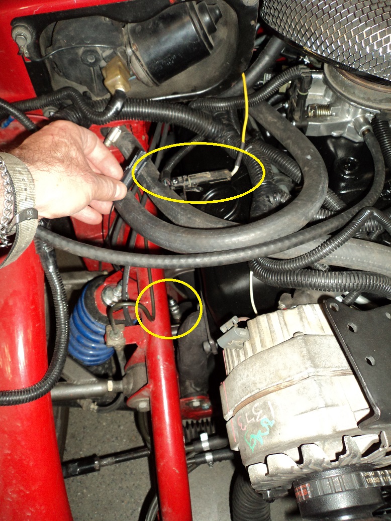
Home-made “WinALDL cable“, plugged into the USB-Serial converter I got from EFI Analytics back when I TunerStudio’d Megasquirt on the Super 7
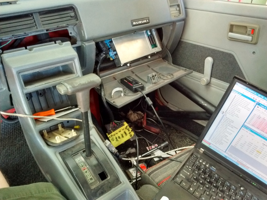
Easy-access ECU. home-made chip-puller-out-inator and Burn2 on the glovebox door. Useless VSS Buffer (yellow) since the car isn’t speed sensoring. Useless PCMCIA-Serial adapter (never did get it to work consistently).
I machined a 0.410″ chunk of aluminum to shim under the Fuel Pressure Regulator spring bucket, which gave me 20psi fuel pressure. Feeding 61lb injectors that were supposed to run on 13psi, should be able to feed about 350hp. That should be ample.
Now to go test and tune….
I -had- been using a spreadsheet I found at gearhead-efi.com that takes your VE table and datalogged BLMs and gives you a new table, but I found it kept trying to make it leaner and leaner and leaner.
More and more I began tweaking the VE table based on what I saw as an average datalogged value of the O2 sensor. To rich? knock it down one or two points. Two lean? Fatten it up one or two points. But I still wasn’t totally happy with the operation.
This evening I went a bit old-school, and set what would be manifold vacuum. That is, I set the lower MAP spark settings (30, 35, 40kPa) base 16° timing plus full 12° vacuum advance, then added mechanical advance. So it idles at 28°, and if you were cruising at 3200rpm you get 48° full advance. This drops right quick from 45kPa to 50kPa, but leaving some decent advance around my 50kPa idle (cruise is 35 – 45kPa).
This felt way, way, way better. Drove better, ran better, idled better. Nice.
There is still a bit of a stumble as I come off throttle, but that might be something to do with the throttle follower.
It has not yet, at any time, fallen on its face in acceleration like the stock 305 did. That’s gotta be a plus.
I’ve learned some new stuff.
The TBI comes with two 61lb/min injectors at 13psi. This is enough fuel for about 225hp.
This engine should theoretically be capable of 325hp. That needs 85lb/min injectors.
85/61 = 1.4, and 1.4×13 = 18psi that I need to run my injectors at.
But, the higher pressure you need to run, the longer it’s going to take to OPEN the injectors (ah! The thought plickens).
In the GM TBI ECU, you need to change the “Injector Bias” if you are changing fuel pressure. If I changed pressure 1.4x, then I need to change the Inj. Bias 1.4x.
I didn’t do that.
But I will tomorrow!
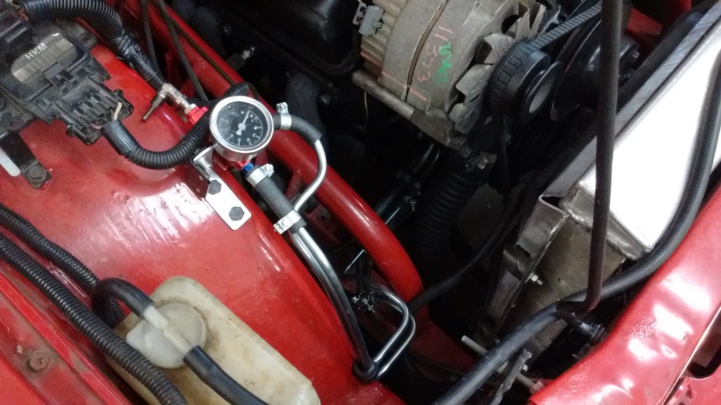
TBI fuel pressure regulator is internal. I had modified it for more fuel pressure, but it wasn’t holding a consistent pressure. And the gauge was all over the place. So I plumbed in an external regulator. Rock steady now!
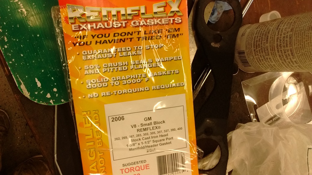
Time to get back to tuning! Still chasing a “lean issue” but I think I found it – a header bolt came undone and blew out the header gasket….. Figures.
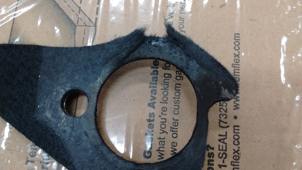
2.5 hours to change one header gasket – I’m getting quicker!
Replaced with Remflex, my favourite. Pictured here so when I Google the part number (#2006), I can find it easier: